Fogco FogCannon HD 160 Operating instructions

Fogco FogCannon ™
HD 160 / HD 230 / HD 300
Pole / Trailer
FOGCO Environmental Solutions
600 S 56
th
Street
Chandler, AZ 85226
Phone: 800-607-6478
Fax: 480-838-2232
Website: www.fogco.com
e-mail: info@fogco.com
Rev080818
Version 1.0
PURPOSE OF USER AND MAINTENANCE MANUAL
Make the operators aware of safety issues;
Install, handle, and use the Machine in safe conditions;
Gain in-depth knowledge on its operation and limits;
Perform maintenance work, correctly and safely,
This document assumes that the safety and hygiene work regulations are observed in the plants, where the
Machine has been located.
The instructions, drawings and documents contained in this Manual are of a confidential and technical
nature, of strict ownership of the manufacturer and cannot be reproduced in any way without prior consent
from the manufacturer.
The Instruction Manual should be kept with the Machine at all times. Copies available at www.fogco.com.
The Manufacturer reserves the right to modify the design and make improvements to the Machine without
communicating it to the Customer and without updating the manual already delivered to the user.
PICTOGRAMS
Sym.
Description
General unskilled worker: operator with no specific skill,
able to perform simple tasks upon orders of qualified
technicians.
Operator of lifting and handling: operator familiar with
the use of lifting and handling of materials and machines
(following the instructions of the manufacturer), in
accordance with the laws in force in the country of use of
the machine.
Machine operator - 1st level: operator without specific
skill, able to perform only simple tasks such as the
operation of the machine using the buttons on the Machine
panel or Remote, operations of loading and unloading the
Machine with the protection guards installed and active.
Machine operator - 2
nd
level: operator able to perform
tasks of 1st level operator and also able to perform simple
functions of start, stop and reset following stoppage and
adjustment of the Machine.
Mechanical maintenance worker: qualified technician
able to operate the machine in normal conditions, intervene
on mechanical parts to perform adjustments, or
maintenance work and necessary repair work but. Not able
to work on wiring systems when live.
Electrical maintenance worker: qualified technician able
to operate the machine in normal conditions, intervene in
electrical work of adjustment, maintenance work and
necessary repair work and is capable of working in the
presence of voltage within electrical cabinets and
junction boxes.
Manufacturer’s technician: qualified technician made
available by the manufacturer to perform operations of a
complex nature in specific situations, or in any case, when
agreed with the user. The skills are, depending on the
case, mechanical and/or electrical and/or electronic.
The descriptions preceded by this symbol contain
important information regarding safety.
Failure to respect them can result in danger for the physical safety of the operators; lapse
of warranty; elimination of any manufacturer’s responsiblity.

PICTOGRAMS RELATING TO MACHINE STATUS
The pictograms contained in a square / rectangle provide INFORMATION.
Sym.
Machine status;
Machine off: with electrical and pneumatic power cut
off.
Machine on: with electrical and pneumatic power
connected and in safe stop condition through mobile
protection guards open (specifying which ones); fixed
protectors closed.
Machine on: with electrical and pneumatic power
connected and in safe stop position through mushroom
emergency button in a held position or other control for
this purpose, located close to the intervention zone
(specifying the mushroom or part to use).
Machine in movement: with automatic function, mobile
protection guards closed with relevant blocking device
activated and fixed protector guards closed.
Machine in movement: mobile protector guards closed
with relevant blocking devices activated and fixed
protector guards closed.
Machine in movement: one or more mobile excludable
protection guards open (specifying which) with relevant
interlocking devices deactivated, any remaining mobile
protector guard closed with relevant interlocking devices
activated and fixed protection guards closed.
Machine on: stopped and ready to start (standby
condition) through activation by functional consent (e.g.
presence of product), mobile protection guards closed
with safety device included and fixed protection guards
closed.

PICTOGRAMS RELATING TO SAFETY
The pictograms contained in a triangle indicate DANGER.
The pictograms contained in a circle impose a RESTRICTION OR OBLIGATION.
Sym. Name
Dangerous electrical tension.
Crushing of upper limbs.
Getting caught.
Dragging.
Access forbidden to unauthorized persons.
Do not remove safety devices.
Prohibited to clean, oil, grease, repair or adjust moving
parts by hand.
General danger.
Protection gloves required.
Safety shoes required.
Hard hat required.
Obligation to cut off power before starting repair work

MANUFACTURER DATA
WLP S.r.l.
Via Broletti, 18
38050 Castelnuovo (Trento)
www.wlpdust.com
Exclusive US Partner:
Fogco Environmental Solutions
600 S 56th Street, Unit 9
Chandler, AZ 85226
www.fogco.com
IDENTIFICATION DATA AND MACHINE PLATES
Each Machine is identified by a metal plate that provides the following information:
Machine Product Range
Machine Model Number
Year of Manufacture
Serial Number
Power Requirements
Horsepower
Amp Load
INFORMATION ON TECHNICAL ASSISTANCE
The Machines are covered by warranty as required by general conditions of sale. If the Machine should stop
working smoothly or parts become faulty according to the cases indicated by the warranty, the Manufacturer,
after having made appropriate verifications on the Machine, will repair or replace the faulty parts.
Work performed by the user to alter the machine, without explicit written authorization of the manufacturer,
shall void the warranty and the manufacturer shall not be held liable for damage caused by the faulty
product.
ARRANGEMENTS TO BE PROVIDED BY CUSTOMER
The following are the sole responsibility of the end user:
Arrangement of the site, including any structural work and/or channelling required;
Electrical power of the Machine, according to the laws in force in the country of use;
Grounding of the electrical power when a generator is being used;
Hydraulic power of the Machine, according to the laws in force in the country of use;
Any Pneumatic Power with compressed air.
Pre-filtration for non-potable water use
TRANSPORT AND HANDLING
Before carrying out any operation, it is mandatory to read the entire Instruction Manual.
The transport and the handling of the Machine must be performed in one of the following ways:
HANDLING WITH FORK LIFT: suitable for both TRAILER and POLE versions with base.
A fork lift with lifting force of at least 2200 lbs. and with minimum fork length of 55 inches must be used.
Insert the forks in the proper roll over protective spaces.

HANDLING WITH CRANE: suitable for both TRAILER and POLE versions with or without base.
Use chains or bands with lifting force of at least 2200 lbs. and complete with two lifting hooks. Verify that the
bands or the chains are long enough to avoid them touching the metal parts of the Machine.
Hook and fix the band or the chain to the provided blocking pins only.
INSTALLATION
Before the installation, verify that the ground is adequate to support the weight of the Machine and in the
case of POLE versions verify that the ground is flat and even. The installation must be carried out only by
qualified and authorized staff.
OPERATING PRINCIPLE
The HD 160, HD 230, and HD 300 are dust suppression systems. These machines use water atomization to
capture dust particles (including silica) in the atmosphere.
MAIN COMPONENTS
The machine includes a Cannon, a Multi-Zone Crown, a Column Frame, a Filter, Zone Valves (electric
versions are optional) a PLC Control Panel, and a Pump.
Cannon and Multi-Zone Crown
The ventilation and spray system unit have sufficient water flow to accommodate the air volume and thrust
created from the cannon propeller. The water spray nozzles are located along the circumference of the
crowns. A heating kit (optional) can be installed in order to prevent icing.
Column Frame
The FogCannon is installed on a column frame where the raising and rotation devices are also mounted.
These devices, which can be controlled electrically, manually or in Remote mode, serve to adjust the rotation
angle and to make the fogcannon work within the selected angles set up at the user’s own discretion.
Filter
The unit is fitted with a 100 mesh filter that removes impurities that can clog the nozzles. An additional pre-
filter may be recommended for some applications.
Zone Valves
Manual or electric (optional) valves control the water flow to the various zones on the crown. The HD range
includes a crown that has 2 or 3 zones depending on the machine design. The unit can operate with
individual zones or all zones simultaneously. The water flow depends on the number of zones working, the
nozzle size in each zone, and the operating pressure of the pump. See the OPERATING FLOW OPTIONS
table below.
The electric zone valves (optional) are controlled from the PLC panel or from the Remote Control
Transmitter. When the electric valves are turned off, they automatically drain any remaining water in the
zone lines. It is recommended to open all drain ports on the unit after each use.
PLC Control Panel
The PLC control panel allows the starting of the fan, the pump, the electric zone valves (optional), and
control the electric oscillation and electric tilt (optional) of the FogCannon. The panel also allows for
programming the cycling of the unit.
Pump
The pump is housed on the outer column frame and is used to increase the water supply pressure.
Increased pressure will improve the atomization of the water droplets and the effectiveness of the unit. The
pump is equipped with a pressure gauge and pressure switch which will terminate the pumps operation if the
water supply is insufficient.

CONTROL PANEL DISPLAY
The System status can be viewed on the various pages of the control panel display. Push the key on
the keypad to select the page to view.
PAGE 1
SYS (System): shows if the system is in Manual (MAN) or Automatic (AUT) mode
EV (Electric Valve): shows if the electric valves (1,2,3) are On (1) or Off (0).
ACQ (Acquisition): shows the positions of the acquired rotation points; (0) the machine will search for the 0
point; (1) first point of the angle; (2) second point of the angle.
PAGE 2
PMP (PUMP): Shows if the pump is Off (OFF), On (MAN) or in Auto (AUT)
RADIO (RADIOCOMAND): Shows if the radio is On (ON) or Off (OFF)
HEATER (HEATING SYSTEM): Shows if the heater is On (ON) or Off (OFF).
PAGE 3
TIM (TIMER WORK/PAUSE): Shows if the timer is On (ON) or Off (OFF)
TIM.ON (WORKING TIME) The first column shows the working time in minutes (from 5 to 30 minutes). If the
timer is On, the second column shows the remaining On time.
TIM.OFF (PAUSE TIME) The first column shows the pause time in minutes (from 5 to 30 minutes). If the
timer is On, the second column shows the remaining pause time.
CONTROL PANEL BUTTONS
Turns the fan ON or OFF. Also turns the pump ON or OFF if the pump is in AUTO mode.
Turns the system to AUTO or MANUAL mode.
Turns the pump OFF, AUTO, or ON. AUTO is the recommended default setting.
Raises the cannon if fitted with Electric Tilt.
Changes the Page view between pages 1, 2, and 3.
Turns the electric valve for zone 1 ON or OFF (1/0) if fitted with Electric Valves.
Turns the Radio Control ON/OFF if fitted with REMOTE CONTROL.
Oscillates the cannon to the left.

Sets the auto oscillation rotation angle (See SET THE ROTATION ANGLE instructions below).
Oscillates the cannon to the right.
Turns the electric valve for zone 2 ON or OFF (1/0) if fitted with Electric Valves.
Turns the timer ON/OFF.
Initiates the system at start up and resets any Alarms.
Lowers the cannon if fitted with Electric Tilt.
Shows the required Service.
Turns the electric valve for zone 3 ON or OFF (1/0) if fitted with Electric Valves.
Sets the Time ON for cycling operation.
Sets the Time OFF for cycling operation.
Changes the Heating System settings (when included) only from Page 2.
Shows the required Service.
Raising and lowering of the cannon and opening and closing of the valves is done manually if the unit
is not equipped with Electric Tilt or Electric Valves.
Manually raise/lower the cannon by loosening the cannon Tilt Handle located on the tilt assembly next to the
main control panel; raise or lower the cannon as needed; tighten the Tilt Handle.
Manually open/close the valves for the individual zones on the crown.
CONFIRM FAN ROTATION
After CONNECTING TO THE APPROPRIATE POWER AND WATER SUPPLIES, verify that the primary
selector switch on the FogCannon is ON. Press the blue button on the control panel and press the F1
button on the keypad. The red Tower light stops flashing and the machine is ready for use
Before using the machine, confirm the correct direction of rotation of the Fan by pressing the Fan
ON/OFF key and verify that it turns counter-clockwise or in the direction of the arrow on the backside
of the cannon. If not, pull the plug from the power source and reverse two of the wires. This should
only be done by a qualified electrician.
SET THE ROTATION ANGLE
It is possible to set a rotation angle anywhere between 0° and 340° where the fogcannon oscillates
automatically.
Start by pressing the ACQ key. The fogcannon will rotate clockwise until point 0. Once the cannon
stops at Point 0, press and hold the Left Arrow key until the desired RIGHT stopping point is reached.
Press the ACQ key to set first set point. Press and hold the Left Arrow key until the desired LEFT
stopping point is reached. Press the ACQ key to set the second set point. The ACQ value shown on the
control panel display will show 0 meaning that the desired angle has been set up correctly and that the
machine is ready to operate in the AUTO mode.
After setting the rotation angle, the machine will oscillate automatically when the System (SYS) is set to the
AUTO mode.
OPERATE THE SYSTEM IN MANUAL MODE (manual oscillation)
Use the key to toggle between the 3 pages.
Check the settings on Page 1. SYS should be MAN and all EV should be set to 0;
Check the settings on Page 2. PMP should be AUTO and RADIO should be OFF
Check the settings on Page 3. TIM should be OFF
Press the FAN key to turn the Fan and Pump ON
Press the Electric Valve , , and/or keys (or rotate the manual zone valves if the unit is not
equipped with Electric Valves) to open the appropriate zone(s) on the crown.
The cannon can be rotated by pressing the LEFT and RIGHT arrows. The cannon can be
raised/lowered by pressing the UP and DOWN arrows (or raised and lowered manually if the unit is
not equipped with Electric Tilt).
To terminate the operation, press the FAN key once and press the appropriate Electric Valve , ,
and/or keys once (or rotate the manual zone valves if the unit is not equipped with Electric Valves).
OPERATE THE SYSTEM IN AUTO MODE (auto oscillation)
The Rotation Angle must be set before operating the system in the AUTO mode.
Use the PAGE key to toggle between the 3 pages.
Check the settings on Page 1. SYS should be in MAN; and all EV should be set to 0;
Check the settings on Page 2. PMP should be in AUTO and RADIO should be OFF
Check the settings on Page 3. TIM should be OFF.
Press the Electric Valve , , and/or keys (or rotate the manual zone valves if the unit is not
equipped with Electric Valves) to open the appropriate zone(s) on the crown.
Press the SISTEM key to change the system from MAN to AUTO.
The buzzer will sound for 3 seconds and the cannon will rotate to the 0 position. The cannon will then rotate
to the 1 position. The fan will turn ON. The cannon will continue to rotate to the 2 position. The Pump will
turn ON.
The system will continue to oscillate between position 1 and position 2 until the SISTEM key is pressed
again.
Once the SISTEM key is pressed again, the oscillation, the Fan, the Pump will turn OFF immediately.
All valve (Electric and Manual) must be turned Off separately.
NOTES:
When the system is in AUTO, only the following keys on the display key pad will operate:
The UP and DOWN arrows for raising and lowering the cannon (if equipped with Electric Tilt)
The Electric Valve (EV) keys (if equipped with Electric Zone Valves)

SETTING THE TIMER
It is possible to set up TIME ON and TIME OFF times for the system.
Press the PAGE key on the keypad to select Page 3.
Press the TIM ON key to increase the TIME ON setting (left-hand column) in 5-minute increments from 5
to 30 minutes.
Press the TIM OFF key to increase the TIME OFF setting (left-hand column) in 5-minute increments
from 5 to 30 minutes.
After setting the TIM ON and TIM OFF, the timer can be activated by pushing the TIMER key.
While the machine is operating, the value in the right-hand column for the TIM.ON decreases starting from
the maximum value shown on the left until 0 is reached. Identical procedure is valid for the pause time.
SETTING THE PUMP FUNCTION
Use the key on the keypad to toggle between the 3 pages
Check the settings on Page 1. SYS should be MAN and all EV should be set to 0;
Check the settings on Page 2. PMP should be OFF and Radio should be OFF
Check the settings on Page 3. TIM should be OFF
Press the PUMP key to switch between OFF, AUT, and MAN
When the PMP is set to OFF, it will be deactivated.
When the PMP is set to AUT, it will start automatically whenever the fan is activated and will continue to run
until the fan operation is terminated.
When the PMP is set to MAN, it will start immediately and run until the PMP is set to OFF.
NOTE: The Electric Valves will NOT be automatically activated whenever the pump is running. They must
be turned on seperately by pressing the appropriate EV key on the keypad. The electric valves will NOT be
deactivated when the pump is turned OFF. They must be turned OFF manually by pressing the appropriate
EV key on the display.
SETTING RADIO CONTROL
Transmitter Button controls:
First Row: Tilt UP and DOWN
Second Row: Oscillate Left and Right
Third Row: Fan ON/OFF and Electric Valve 1 ON/OFF
Fourth Row: Electric Valve 2 ON/OFF and Electric Valve 3 ON/OFF
Fifth Row:Not Used
Sixth Row: ON/SYSTEM AUTO mode and Pump ON/OFF
Use the PAGE key to toggle between the 3 pages.
Check the settings on Page 1. SYS should be in MAN; and all EV should be set to 1.
Check the settings on Page 2. PMP should be AUTO and Radio should be OFF.
Check the settings on Page 3. TIM should be OFF.
Press the key on the keypad to select the page 2.
Press the RADIO key to switch from OFF to ON.
Once the RADIO on the machine control panel is set to ON, only the PAGE and RADIO keys will function.
Insert a fully charged battery into the Radio Transmitter
Pull out the red tab on the top of the Transmitter.
Briefly press the Transmitter ON button (bottom left hand position on the Transmitter)
Then hold the same button down until the LED light begins flashing green.
The transmitter is now ready to use and provides the following functions:

SYSTEM AUTO mode is initiated by pressing and holding the SYSTEM AUTO button for 3 seconds.
SYSTEM AUTO mode is terminated by pressing the SYSTEM AUTO button again.
Turn OFF the RADIO mode by pressing the RADIO button on the control panel keypad.
Turn OFF the Radio Transmitter by pushing the red tab on the top of the Transmitter inward.
OPERATING FLOW OPTIONS
The individual zones on the crown can be operated seperately or simultaneously creating a wide range of
flow options for the unit. The table below provides approximate flow given the standard nozzles and the
number of zones being used.
GPM Flow Using Various Zones
HD 160 HD230
HD 300
Zone 1 6 4.2 4.2
Zone 2 9 8.3 8.3
Zone 3 N/A 12.5 12.5
Zone 1/2 15 12.5 12.5
Zone 1/3 N/A 16.7 16.7
Zone 2/3 N/A 20.8 20.8
Zone 1/2/3 N/A 25 25
HD 160: Dual Zone with 36-10 GPH and 36-15 GPH nozzles
HD230: Triple Zone with 50 - 5 GPH, 50-10 GPH; and 50-15 GPH nozzles
HD300: Triple Zone with 50 - 5 GPH, 50-10 GPH; and 50-15 GPH nozzles

ALARMS
The page EMERGENCY STOP indicates that the emergency stop button, which is placed on the side
of the control panel, has been pushed manually or that a malfunctioning occurred causing the safety
relay to stop the machine. The red Tower Light starts flashing.
SOLUTION: Verify the origin of the malfunction and if necessary, contact Fogco Technical Assistance.
Only after that the malfunction is solved, pull the emergency stop button and reset the internal breaker
as described below.
The alarm WRONG ROTATION – INVERT PHASE indicates that one of the electrical phases is
inverted. In this case, the angle cannot be set up in automatic mode.
SOLUTION: Contact a qualified electrician to invert the phases.
The alarm appears when the automatic mode had been selected and the angle had not been set up.
SOLUTION: Follow the SET THE ROTATION ANGLE instructions above.
This alarm indicates that the pump is not supplied with enough water. The pump stops and the red
and yellow Tower Lights mounted on the frame start flashing for three minutes.
SOLUTION: The machine starts working again automatically if the pump receives the correct water
quantity again within three minutes. The machine stops automatically if the water flow is not restored
within three minutes. Verify the origin of the malfunction. Press the F1 to reset key only after solving
the malfunction.
This alarm appears when a problem at one of the motors arises. The corresponding safety switch
blows.
SOLUTION: Check the origin of the malfunction and contact a qualified electrician. If the malfunction
can be attributed to a loss of current, restore the machine by turning the motor start selector switch in
position 1. If the malfunctioning persists, contact the authorized Technical Assistance Service.
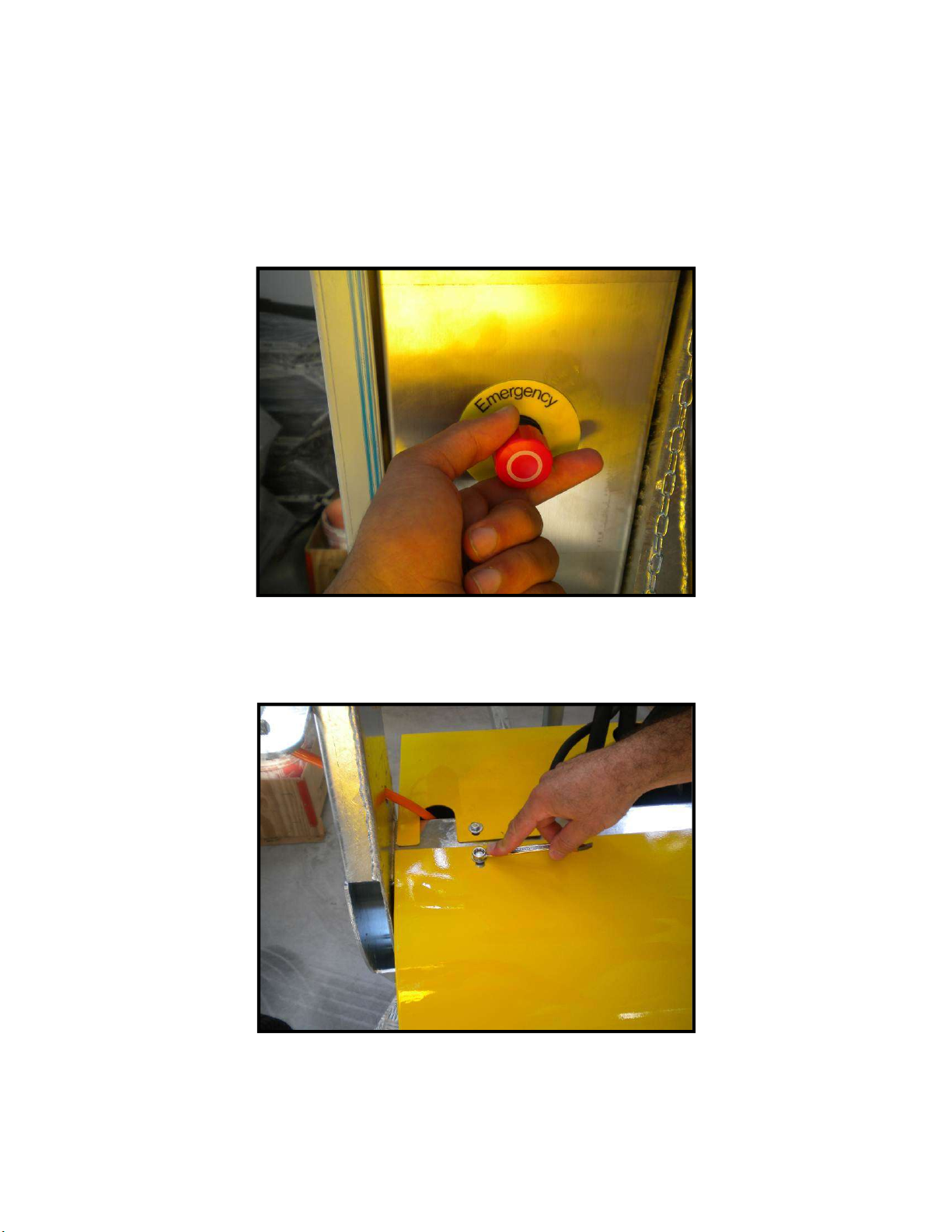
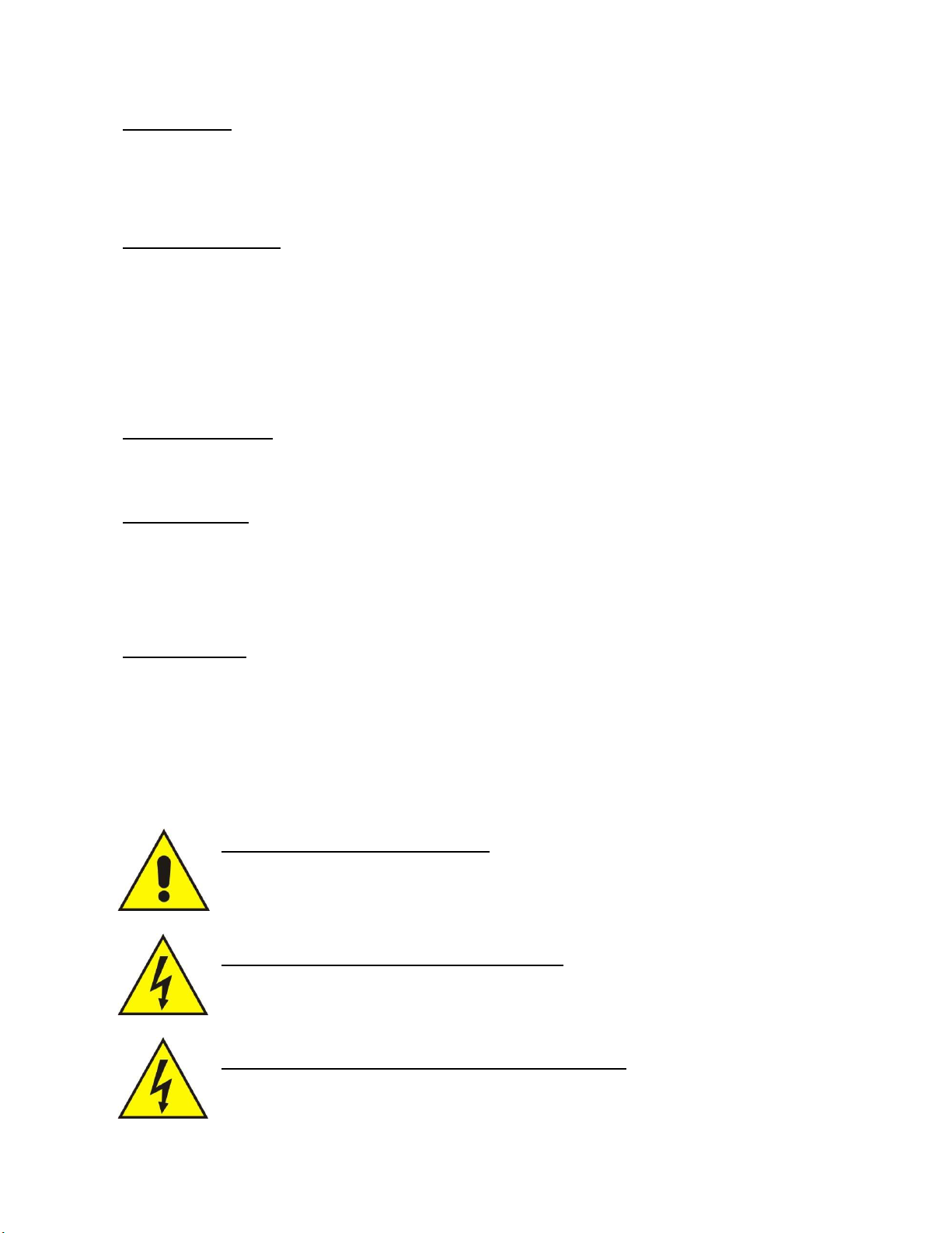
SWITCH-ON THE CIRCUIT-BREAKER
When the machine is stopped with the emergency stop it requires to switch-on the circuit-breaker with the
following procedure:
Restore the emergency stop.
Dismount the front protection using a 10 mm wrench
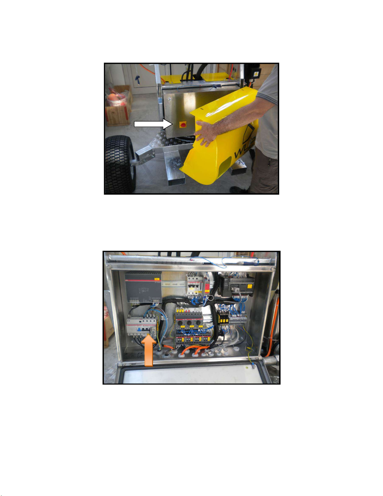
Remove the front protection and switch off the main switch (white arrow)
Open the electric cabinet and look for the blue colored circuit breaker (orange arrow)
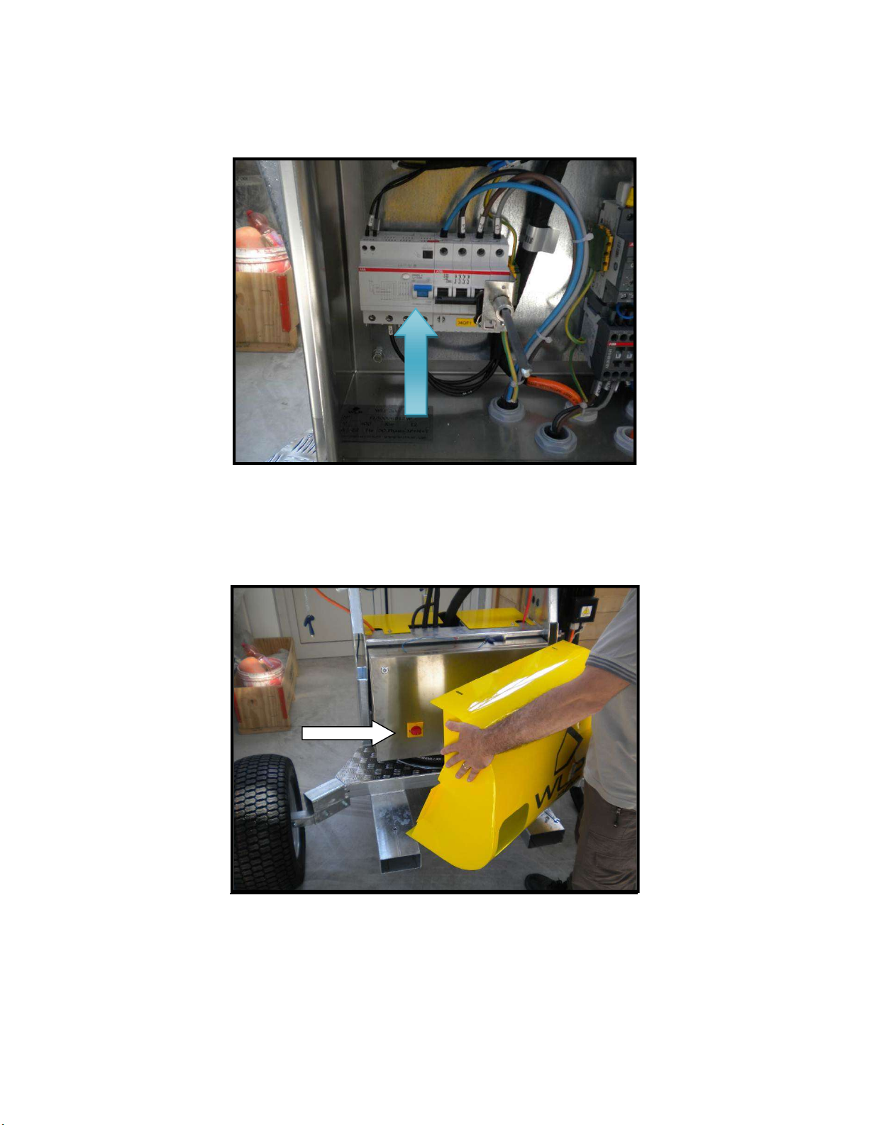
Lift –up the switch as shown in picture (blue arrow)
Close the electric cabinet and the front protection.
Switch –on the main switch (white arrow)

3. DIMENSIONS
MODEL
WEIGHT (
Lbs
)
DIMENSIONS (
inches
)
H
L
W
HD 160 Pole with iron base 1455 103 48 48
HD 160 Trailer 950 88 98 75
HD 230 Pole with iron base 1630 103 48 52
HD 230 Trailer 1125 88 98 75
HD 300 Pole with iron base 1720 103 48 52
HD 300 Trailer 1215 103 98 75
ENVIRONMENTAL CONDITIONS
The Machine does not need to work in specific environmental conditions. It can be installed in an industrial
building where the electrical equipment has at least IP55 protection, the ventilation is good and the floor is
solid and level.
ATTENTION – the machine must not be used in environments with an explosive or corrosive atmosphere.
The machine may be used in environments with:
Temperatures between 40° F and 100° F, with a mean temperature of 90° F;
Relative humidity ranging from 30 to 95%.
The machine may not be used in environments with:
A corrosive atmosphere;
A risk of fire;
An explosive atmosphere;
A risk of stones being ejected;
Water and chemical substances that could mix and create hazards.
LIGHTING
The installation area must be illuminated in accordance to the local codes or regulations in force. The lighting
should ensure good all-round visibility, create no dangerous reflections, make it possible to read the writing
on the control panels clearly and easily and locate the emergency buttons without trouble.
VIBRATIONS
The vibrations do not generate any risk of danger if the machine is used properly according to the manual
instruction. If you are planning to install the machine in an area where there is a strong risk of vibration, you
should fit vibration dampeners of adequate size between the machine and the source of vibration. The
dampeners require a written declaration of approval issued by Fogco.

TECHNICAL DATA
Description HD 160 HD 230 HD300 Volts
Fan Motor HP 7.5 15 25 480 VAC / 60 Hz
Pump Motor HP 3 5 5 480 VAC / 60 Hz
Oscillation Motor HP .1 .1 .1 24 VDC
Full Load Amps 21 32 45
STANDARD SUPPLY
The machine is supplied ready for use and includes the User’s Manual and Data plate with Machine
technical information;
GENERAL SAFETY WARNINGS
The manufacturer has done his utmost in designing this Machine to be INTRINSICALLY SAFE and is fitted
with all necessary protective and safety devices and is supplied with the information for its proper use.
The user can appropriately integrate the information provided by the manufacturer with supplementary work
instructions to ensure safe use of the Machine and must not be in contrast with the instructions given in this
Manual,
It is forbidden to operate the Machine in Auto mode with the fixed/mobile protection devices dismantled;
It is forbidden to inhibit the safety devices installed on the Machine;
It is forbidden to stand in front of the Machine when it is in operation;
Before carrying out any repair or maintenance, the Machine must be switched off and disconnected from
the water and power supply networks;
All maintenance operations must be performed by qualified and authorized staff;
It is mandatory to wear the necessary personal protection devices;
It is mandatory to respect and observe all alarms and warnings;
In the event of a malfunction of a component, the failed component must be replaced with and exact
duplicate. The manufacturer shall not be held liable for the consequences when generic parts are used
to replace factory authorized parts. Modification requests must be directed to the manufacturer;
Clean the machine, panels and controls with soft dry cloth or slightly soaked in a neutral detergent
solution. Do not use any type of solvent, such as alcohol or petrol, as the surfaces could be damaged;
The washing operations must be performed with the electrical and pneumatic separation devices cut off;
it’s strictly forbidden to use high pressure systems for washing the machine and/or its inner parts.
It is absolutely forbidden to move the machine when operating with lifting means
of any nature and kind. The machine can be moved exclusively with hydraulic
and electrical devices uncoupled and the frame must be blocked with the
appropriate pins to the lift forks. The spring pins must be inserted into the
blocking pins.
USE POTABLE WATER ONLY
Before putting the Machine into operation carefully read the instructions set out in this
Manual and follow the indications provided in it.

General instructions
All the safety devices mounted on the mobile parts to avoid accidents and to ensure safety cannot be altered
or removed and they must be properly protected. Users must inform immediately their employers or direct
supervisors about any defect or anomaly found on the mobile parts.
Checks and verifications
The Machine must be thoroughly inspected prior to each use. If worn or faulty parts are not promptly
replaced, the manufacturer will not be responsible for damage or accidents which could occur.
The verifications must be performed by qualified staff and must be of visual and functional kind, with the
purpose of guaranteeing the machine safety. They include:
verification of all the supporting structures, which must not present any crack, breakage, damage,
deformation, corrosion, wear, or alteration compared with the original characteristics;
verification of all mechanical parts;
verification of all safety devices installed on the machine;
verification of all the connections with pins and screws;
functional verification of the machine;
verification of machine status;
verification of seal and efficiency of the pneumatic system.
If the person performing the verification finds cracks or dangerous anomalies, he is obliged to give prompt
communication of this to the manufacturer. The Machine must be taken out of service until operating
anomalies are verified and corrected or repaired.
Certify that there are no objects between the Machine parts.
Check that no object remains between the moving parts after any maintenance work.
To guarantee the maximum safety in handling the Machine it is FORBIDDEN to:
Alter any Machine part;
Leave the moving elements unprotected;
Use the machine in operation, but not in complete efficiency,
Alter the machine to change the established original use, without explicit authorisation of the
Manufacturer or without assuming full responsibility set by D.P.R. 459/96 (Machine Directives);
Handle moving parts manually in case of lack of energy;
IMPORTANT !
The Manufacturer shall
NOT be
liable for any damage caused by the
Machine in case of:
- use of the Machine by staff without necessary training;
- improper use of the machine;
- faults in electrical, hydraulic or pneumatic power;
- incorrect installation;
- failure to perform maintenance work required;
- unauthorized alterations or work;
- use of spares that are not original or not specific to the model;
- partial or total failure to observe the instructions;
- use contrary to national specific legislation;
- calamities and force majeure or extraordinary events.
ATTENTION!
If anomalies are found, they must be eliminated before starting the machine again, and
the expert who performs the verification must make a note of it on the repair sheet, giving
his
consent to use the machine.
INTENDED USE
The machine has been designed to work as a system to suppress dust on worksites and quarries by the
exclusive use of potable water. Any use with products/materials other than that mentioned is considered
incorrect or improper, can damage the machine and create dangerous situations for the operator and/or
persons close to the Machine.
CONTRAINDICATIONS
The Machine must not be used:
For uses other than those set out in this Manual;
In explosive or corrosive atmosphere, with oily substances in suspension in air;
With water supply pressure greater than 140 PSI;
In atmosphere with risk of fire;
With safety devices cut off or not operating;
With electric bridges and/or mechanical means which exclude utilities/parts of the Machine itself;
DANGEROUS ZONES
Dangerous zones include but are not limited to electrical substation or areas where there are electrical parts
with IP level lower than IP 55 and/or areas where there is the risk of explosion
SAFETY DEVICES
In the Machine the following safety devices are installed:
1. Emergency shutdown from the main control panel as well as the other emergency shutdown devices of
the Machine.
RESIDUAL RISKS
DEFINITION OF RESIDUAL RISK:
“ danger not totally traceable through the design and technique of protection, or rather, potential non
evident danger”
It is necessary to pay attention to the following residual risks which are present upon use of the machine and
cannot be eliminated.
CAUTION: DANGEROUS MOVEMENTS
No people other than the operator must stay around the machine. In the presence of
third people, immediately stop the machine and force them to move away.
CAUTION: ELECTRICAL RISKS FOR LIVE PARTS
CAUTION: ELECTRICAL RISKS FOR RESIDUAL VOLTAGE

Other residual risks can be identified by introducing bodies within the fan when it is in operation and when it
is off. The introduction of solid bodies can cause immediate breakage of the fan with consequent projection
of the parts outside the machine. This situation can endanger people and cause damage to things within the
range of action of the machine.
GENERAL MAINTENANCE INSTRUCTIONS
The HD 160, HD 230, and HD 300 require the following maintenance:
Water filter: Check the condition of the filter each time before starting up the
machine. Unthread the filter cannister to access the filter. Clean the filter with a jet
of water. As necessary, remove the O-ring and soak the filter in nozzle cleaner for
30 minutes. Flush with hot water. Re-install. Any traces of iron oxide (rust), scale or
other form of oxidization on the surface of the filter are a result of poor water quality.
Additional filtration may be needed.
Remove any residue of organic substances, such as small algae, using neutral
soap. Do not use cleaning solvents as these can damage the O-rings on the filters.
Make sure the filter is properly in place before threading on the cannister. Check the
condition of the seals before putting the machine into service.
Nozzles: Remove the nozzles by hand using a 5/8” socket. Disassemble the
nozzles using a 5/8” socket/wrench and a 5/32 Allen wrench. Brush slots on the top
of the nozzle inserts with a stainless steel wire brush to remove all debris. Remove
the O-ring from the nozzle body. Soak the nozzle body and insert in nozzle cleaner
for 30 minutes. Flush with hot water and then compressed air. Re-assemble.
Inspect nozzle threads Clean the nozzle and crown threads as necessary. Thread
the nozzle into the crown (hand tight only).
Plumbing: Flush with potable water and drain the unit after each use. Periodically
(or under freezing conditions), clean and drain the unit plumbing by removing the
hose that feeds the nozzle crown and flush the units plumbing by running the pump
with potable water for 30 seconds. Remove the top nozzle from each crown and
insert a pressurized water supply into the open nozzle port to flush the crown.
Repeat with compressed air. Replace the nozzle. Replace the feed hose. Open all
drain valves.
Water pump: consult the respective manual.
Keep the system clean at all times.
Before putting the machine into
operation,
it is mandatory to
read this manual carefully and
to make sure you understand all the instructions.
All
information and instructions provided in this manual must be respected and
observed.
Record all maintenance in the maintenance table.
Contact the Technical Assistance Service or the Manufacturer before carrying out
any repair, change of the Machine and/or extraordinary maintenance operations.
This manual suits for next models
2
Table of contents
Popular Industrial Equipment manuals by other brands


NANOTEC
NANOTEC PD4-C Technical manual

Siemens
Siemens SINAMICS G120 instruction manual

Schulte
Schulte FLX-1510 Operator's manual

THORLABS
THORLABS PDA400 operating manual

Bühler technologies
Bühler technologies GAS 222.21 E 2 Series Installation and operation instruction

Universal
Universal Radial 8 Reference manual


