manuals.online logo
Brands
  1. Home
  2. •
  3. Brands
  4. •
  5. Festo
  6. •
  7. Industrial Equipment
  8. •
  9. Festo MS4-LFR B Series User manual

Festo MS4-LFR B Series User manual

MS4-LFR-...-B
Filter regulator
Festo SE & Co. KG
Ruiter Straße 82
73734 Esslingen
Deutschland
+49 711 347-0
www.festo.com
Operating instructions
8160211
2021-06a
[8160213]
Translation of the original instructions
© 2021 all rights reserved to Festo SE & Co. KG
1Applicable documents
All available documents for the product è www.festo.com/sp.
Documents Product, type Table of contents
Assembly instructions Mounting bracket, MS4/6-WR –
Tab. 1: Applicable documents
2Safety
2.1 Safety instructions
–Only use the product in original status without unauthorised modifications.
–Only use the product if it is in perfect technical condition.
–Observe labelling on the product.
–Take into consideration the ambient conditions at the location of use.
–Prior to mounting, installation and maintenance work: Switch off compressed
air supply and secure it from being switched back on.
2.2 Intended use
The filter regulator LFR is designed to regulate the compressed air in the down-
stream string to the set outlet pressure. The filter regulator LFR smooths pressure
fluctuations and removes dirt particles and condensate from the compressed air.
2.3 Training of qualified personnel
Work on the product may only be carried out by qualified personnel who can
evaluate the work and detect dangers. The qualified personnel have knowledge
and experience in pneumatics.
3Additional information
–Contact the regional Festo contact if you have technical problems
è www.festo.com.
–Accessories è www.festo.com/catalogue.
4Product design
1
2
3
4
5
6
7
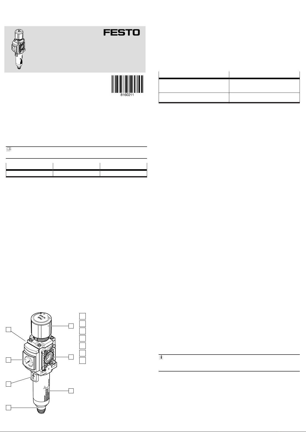
Fig. 1: Product design
1
Rotary knob
2
Pneumatic connection P2
3
Filter bowl
4
Drain screw
5
Release button
6
Pressure gauge
7
Pneumatic connection P1
5 Assembly
5.1 Mounting distances
• Maintain sufficient space around the product.
–Space required above the product: ³ 20 mm
–Space required under the product: ³ 30 mm
–Space required left and right of the product: ³ 30 mm
With sheet metal mounting:
–Mount product vertically.
–Observe the maximum permissible wall thickness. Wall thickness: £ 2.5 mm
5.2 Types of Mounting
Mount product with one of the following types of mountings depending on the
purpose:
Type of mounting Continuing description
Wall mounting with mounting bracket –Assembly instructions è 1 Applicable docu-
ments
–è 5.4 Installation
Sheet metal mounting –è 5.1 Mounting distances
–Accessories è www.festo.com/catalogue
Tab. 2: Types of Mounting
5.3 Preparation
1. Observe the mounting position è Technical data.
2. Note the flow direction as shown by the numbers on the housing: from 1 to 2.
3. To exhaust the system for maintenance:
Use shut-off valves in the compressed air supply line.
4. Use mounting accessories from the Festo catalogue
è www.festo.com/catalogue.
5. Note types of mounting.
5.4 Installation
1. Place product at the installation site.
2. Note the flow direction as shown by the numbers on the housing: from 1 to 2.
3. Observe mounting clearances è 5.1 Mounting distances.
4. Place the mounting bracket on the product.
5. Tighten mounting bracket with nut è 1 Applicable documents .
6. Secure mounting bracket to the mounting surface.
6 Installation, pneumatic
1. Use fittings, seals and suitable tubing from the Festo catalogue
è www.festo.com/catalogue.
2. Screw fittings into the pneumatic ports.
3. Note maximum screw-in depth of the connector thread. Screwing in deeper
will reduce the flow rate. Screw-in depth: £ 6.5 mm
4. Push suitable tubing into the fitting up to the stop.
–Position tubing axial to the pneumatic ports.
–Do not bend the tubing more than the minimum bending radius.
7 Commissioning
7.1 Setting the output pressure
1. Unlock rotary knob [1] (pull).
2. Turn rotary knob [1] completely in the "z" direction.
3. Pressurise system slowly: turn the rotary knob in the "+" direction until the
desired pressure is reached.
Maintain permissible pressure regulation range è Technical data.
The input pressure p1 should always be at least 0.1 MPa (1 bar, 15 psi) higher
than the set output pressure p2.
4. Lock rotary knob [1] (press).
8 Maintenance
8.1 Draining the condensate
Draining the condensate manually
If the condensate reaches a level approx. 10 mm below the filter element:
1. Turn drain screw [4] anticlockwise as seen from below.
ÄThe condensate flows out.
2. Turn drain screw [4] clockwise as seen from below.
Draining condensate automatically
The filter drains automatically.
8.2 Changing the filter
Replace the filter cartridge if the flow rate is reduced even though the pressure
setting is unchanged.
1. Exhaust product.
2. Pull the release button [5] on the filter bowl down.
3. Turn filter bowl [3] anticlockwise manually (as seen from below) until the stop
can be felt.
4. Pull filter bowl [3] from the housing.
5. Unlock the latch on the support module by pressing in on the upper edge.
6. Pull the support module upwards.
7. Unscrew the spin disc and remove the filter support.
8. Install new filter cartridge:
–Grip the filter cartridge and push it onto the filter support.
–Screw in the spin disc and tighten it lightly by hand. Tightening torque:
0.4 Nm ± 10 %
9. Press the spin disc into the filter bowl until the lock audibly engages at the
end stop.
10. Mount filter bowl [3]:
–Align lock release of filter bowl with the cutout on the housing and insert it.
–Turn filter bowl clockwise until the lock audibly locks at the end stop.
8.3 Cleaning
•Clean the outside of the product as required with a soft cloth.
Permissible cleaning agents:
–Soap suds (max. +60 °C)
–Petroleum ether (free of aromatic compounds)
9Fault clearance
Fault description Cause Remedy
Low flow rate, operating pres-
sure drops with air consump-
tion.
Constriction in the supply line. Check supply line.
Filter cartridge dirty. Replace filter cartridge
è Maintenance.
Pressure increases above the
set working pressure.
Valve disc defective at sealing
seat.
Replace product.
Continuous audible blowing
noise at rotary knob.
Valve seat damaged. Replace product.
Audible blowing noise at the
drain screw.
Drain screw leaking. Replace product.
Tab. 3: Fault clearance
10 Disassembly
1. Exhaust the complete system and product.
2. Release interlock at the fittings by pressing it and pull out hose assembly.
3. Release fittings at the connecting flanges and unscrew.
11 Technical data
11.1 Technical data, mechanical
MS4-LFR-... -M -VC
Mounting position [°] vertical +/– 5
Condensate drain function manual turning manual non-detenting
fully automatic
Vibration and shock resistance Severity level 1 in accordance with IEC 60068.
Thread size
Pneumatic connection P1 G1/4
Pneumatic connection P2
Temperature ranges
Temperature of medium [°C] –5 … +50 5 … 50
Ambient temperature [°C] –5 … +50 5 … 50
Storage temperature [°C] –5 … +50
Tab. 4: Technical data, mechanical
Type of severity level (SL)
Vibration load
Frequency range [Hz] Acceleration [m/s2]Deflection [mm]
SL1 SL2 SL1 SG2 SL1 SL2
2 … 8 2 … 8 – – ±3.5 ±3.5
8 … 27 8 … 27 10 10 – –
27 … 58 27 … 60 – – ±0.15 ±0.35
58 … 160 60 … 160 20 50 – –
160 … 200 160 … 200 10 10 – –
Shock load
Acceleration [m/s2]Duration [ms] Shocks per direction
SL1 SL2 SL1 SL2 SL1 SL2
±150 ±300 11 11 5 5
Continuous shock load
Acceleration [m/s2]Duration [ms] Shocks per direction
±150 6 1000
Tab. 5: Type of severity level (SL)
11.2 Technical data, pneumatic
MS4-LFR-... -M -VC
Compressed air quality
Operating medium Compressed air in accordance with ISO 8573-1:2010
[7:4:4]
Inert gas
Note Not compatible with ester oil.
Air quality class at the output
MS4-LFR-...-C
Grade of filtration 5 µm
Compressed air in accordance with ISO 8573-1:2010
[6:4:4]
MS4-LFR-... -M -VC
MS4-LFR-...-E
Grade of filtration 40 µm
Compressed air in accordance with ISO 8573-1:2010
[7:4:4]
Pneumatics
Operating pressure [MPa] 0.1 … 1 0.2 … 1
[bar] 1 … 10 2 … 10
[psi] 15 … 145 29 … 145
Pressure regulation range [MPa] 0.03 … 0.7
[bar] 0.3 … 7
[psi] 4.35 … 105
Standard nominal flow rate
MS4-LFR-...-C
Grade of filtration 5 µm
[l/min] 1500
MS4-LFR-...-E
Grade of filtration 40 µm
[l/min] 1700
Tab. 6: Technical data, pneumatic

Other Festo Industrial Equipment manuals

Festo EAMM-A-T42-55A User manual

Festo

Festo EAMM-A-T42-55A User manual

Festo EPCC-BS-KF User manual

Festo

Festo EPCC-BS-KF User manual

Festo 571815 User manual

Festo

Festo 571815 User manual

Festo VMPA-HB B Series User manual

Festo

Festo VMPA-HB B Series User manual

Festo CRDSNU Series Setup guide

Festo

Festo CRDSNU Series Setup guide

Festo VT32 Series User manual

Festo

Festo VT32 Series User manual

Festo EduTrainer 8040011 User manual

Festo

Festo EduTrainer 8040011 User manual

Festo YSRWJ User manual

Festo

Festo YSRWJ User manual

Festo FLSM Series User manual

Festo

Festo FLSM Series User manual

Festo PF-10-SLT User manual

Festo

Festo PF-10-SLT User manual

Festo MPS 200 User manual

Festo

Festo MPS 200 User manual

Festo CRDSNU Series User manual

Festo

Festo CRDSNU Series User manual

Festo KYP Series User manual

Festo

Festo KYP Series User manual

Festo VABD Series User manual

Festo

Festo VABD Series User manual

Festo ELGS-BS Series User manual

Festo

Festo ELGS-BS Series User manual

Festo CPX-AB-1-7/8-DN User manual

Festo

Festo CPX-AB-1-7/8-DN User manual

Festo DGSL User manual

Festo

Festo DGSL User manual

Festo MS6-SV-C-MK User manual

Festo

Festo MS6-SV-C-MK User manual

Festo VPPE-3-1-1/8 E1 Series User manual

Festo

Festo VPPE-3-1-1/8 E1 Series User manual

Festo CRHD Series Setup guide

Festo

Festo CRHD Series Setup guide

Festo VTEM User manual

Festo

Festo VTEM User manual

Festo HGPL-B Series User manual

Festo

Festo HGPL-B Series User manual

Festo ESG Series User manual

Festo

Festo ESG Series User manual

Festo MPS 8034567 User manual

Festo

Festo MPS 8034567 User manual

Popular Industrial Equipment manuals by other brands

ABB HT572607 Operation manual

ABB

ABB HT572607 Operation manual

Clarke C18H instruction manual

Clarke

Clarke C18H instruction manual

Vestil BOL Series quick start guide

Vestil

Vestil BOL Series quick start guide

torgar PL-15 EXT-DC manual

torgar

torgar PL-15 EXT-DC manual

Graco G-Flex 1500 Operation - repair - parts

Graco

Graco G-Flex 1500 Operation - repair - parts

Dover OPW 788 Series quick start guide

Dover

Dover OPW 788 Series quick start guide

Siemens 3VW9011-0AN73 operating instructions

Siemens

Siemens 3VW9011-0AN73 operating instructions

ABB HT572399 Operation manual

ABB

ABB HT572399 Operation manual

Humboldt H-4156M product manual

Humboldt

Humboldt H-4156M product manual

Sur-Pro WIT110 user manual

Sur-Pro

Sur-Pro WIT110 user manual

ABB RELION 650 SERIES Product guide

ABB

ABB RELION 650 SERIES Product guide

Kitagawa SR1146 instruction manual

Kitagawa

Kitagawa SR1146 instruction manual

Scheppach HSC120 Translation of original instruction manual

Scheppach

Scheppach HSC120 Translation of original instruction manual

QSA Global OPENVISION DX OVDX-NDT-70 Software manual

QSA Global

QSA Global OPENVISION DX OVDX-NDT-70 Software manual

Kollmorgen RGM 14 user manual

Kollmorgen

Kollmorgen RGM 14 user manual

Graco Sharpe 7004 Instructions - parts

Graco

Graco Sharpe 7004 Instructions - parts

Viessmann 5548 Operation manual

Viessmann

Viessmann 5548 Operation manual

ABB HT604228 Operation manual

ABB

ABB HT604228 Operation manual

manuals.online logo
manuals.online logoBrands
  • About & Mission
  • Contact us
  • Privacy Policy
  • Terms and Conditions

Copyright 2025 Manuals.Online. All Rights Reserved.