Bastian Solutions RZPAC Manual

Installation and Maintenance Manual
Model: RZPAC
Effective February 2022
Rev. B

Installation and Maintenance Manual: RZPAC
Published November 2021
Rev. B
2
Contributions
ROLE
NAME
TITLE
Author
Ben Baker
Senior Design Engineer
Checker
Brad Paris
Senior Design Engineer
Approver
Sam Osterhout
Design Team Lead
Revisions
DATE
REVISION
DESCRIPTION
AUTHOR
11/12/2021
A
Initial Document Creation
Ben Baker
2/18/2022
B
Document Branding and Formatting
Andrew W. Jones

Installation and Maintenance Manual: RZPAC
Published November 2021
Rev. B
3
Term and Acronym Definitions
TERM/ACRONYM DEFINITION
2 Groove
Roller format which uses O-Rings to transfer rotational motion from one roller
to another in DC conveyor.
AC Alternating current
Accumulation
The collection or staging of multiple cartons, cases, or totes of product on
conveyor.
ATO Assembled to Order; Orders consisting of standard products
Back pressure
Pressure against carton(s) in the direction of carton flow resulting from weight
of densely accumulated cartons.
BF Between frame; this refers to the distance between conveyor bed side frames.
BHCS Button head cap screw
BOM Bill of Materials
Carton or Case Term for a conveyable item (cardboard box, tote, etc.)
CB Carriage bolt
CCW Counter-clockwise
CDAC 1.0
Conveyor Director Control Card 1.0 - Bastian Solutions' dual zone control card
designed for zero pressure control of low-voltage (24V nominal) DC solenoids
for belt-under roller conveyor.
CDDC 1.0
Conveyor Director Control Card 1.0 - Bastian Solutions' dual zone control card
designed for zero pressure control of low-voltage (24V or 48V nominal) DC
powered MDRs.
Center Drive
Drive format of AC conveyor where the drive unit is mounted underneath the
conveyor.
CW Clockwise
DC Direct current
Diffuse
A photoeye format that houses both the emitter and receiver and senses an
object when the light beam is reflected back to the sensor. This type of
photoeye is a standalone unit and does not use reflectors.
Discharge
The point where cartons, cases, or totes exit a conveyor or similar unit used in
a material handling system.
Divert
(noun) A conveyor unit used to change the direction of a carton, case, or tote
in a controlled manner. (verb) To change the direction of a carton, case, or
tote in a controlled manner.
Double-dispense
Event in which two or more cartons are dispensed when a single carton, case,
or tote is requested. This is generally a result of two cartons, cases, or totes
being in full contact just prior to reaching the dispensing point.
Drive Card
A control card used to power and control the logic of one or more zones of
zero pressure conveyor.
Drive Pulley
A motor-driven pulley used to transmit rotational energy to linear motion in AC
belts.
Dutchman
A short, removable section of belt used to take up slack developed in AC belts
after they have stretched from long term use.
End stop
A plate mounted to the end of a conveyor with the intent of stopping and
holding a carton, case, or tote in position until removed by a user or diverted
by a conveyor unit.

Installation and Maintenance Manual: RZPAC
Published November 2021
Rev. B
4
TERM/ACRONYM DEFINITION
E-stop
A highly visible button or pull cable designed to shut down equipment in the
case of an emergency.
ETO Engineered to Order; Orders requiring custom Engineering
FAT Factory Acceptance Testing
Flange
A feature in sheet metal consisting of a face and bend connected to an
existing face along a straight edge.
Flash
Excess material left on a part by a molding or forming process, created by
material leaking between the separate parts of the mold.
Gapping
The separation of cartons, cases, or totes. Generally done by progressively
increasing the speed of consecutive zones or belts, forcing cartons, cases, or
totes to "pull a gap."
Guide Rail
Mechanism used to maintain the desired position of conveyable cartons,
cases, or totes on their respective conveying surface.
HHCS Hex head cap screw
ID Inner diameter of a circular, cylindrical or arced body.
Idler Roller Conveyor roller that is unpowered and used to support a belt.
Infeed
The point where cartons, cases, or totes enter a conveyor or similar unit used
in a material handling system.
Live
A conveyor or zone which runs in response to a simple “enable” signal or runs
whenever power is applied, without any zero pressure accumulation logic.
LOTO Lockout Tagout
Mark Number
A numeric or alphanumeric term used to uniquely identify a conveyor bed or
collection of beds (of similar model type) within a material handling system.
Match
A mark made on mating conveyor assemblies to assist in identifying
orientation and placement within a system.
MDR
Motorized drive roller; DC powered conveyor roller with an internally mounted
motor which may be controlled via internal or external commutation.
Minimum Pressure
Allows cartons, cases, or totes to lightly touch with up to 2% back pressure
while being conveyed to eliminate product damage.
OAW
Overall width of any given conveyor bed, measured between the outside
flanges of the sideframes.
OD Outer diameter of a circular, cylindrical, or arced body.
O-Ring
A urethane ring or band with a circular cross section used for power
transmission in DC conveyor applications.
OSHA Occupational Safety and Health Administration
PE
Photoeye; Device used to detect the presence of an object by sensing a light
beam. Common types are diffuse, retroreflective, and through-beam.
PELV
Protected Extra Low Voltage, a voltage level (less than 60V DC or 25Vrms AC
in the context of EN 60204-1) that is low enough to be safe in the case of
indirect or small area direct contact. PELV circuits are required to be
connected to earth ground.
PM Project Management (or Project Manager)
PO Purchase Order
Polytier
Heavy duty floor support with a wide stance, capable of supporting multiple
levels and types of conveyor.
PPE Personal protective equipment

Installation and Maintenance Manual: RZPAC
Published November 2021
Rev. B
5
TERM/ACRONYM DEFINITION
Prox Sensor
A sensor able to detect the presence of nearby objects without any physical
contact.
Pulley
Mechanical device used to change the direction of the belt in a conveyor
system, to drive and/or tension the belt.
Reflector
A reflective component needed for retroreflective photoeyes to receive
transmitted light or radiation when no object is in front of the photoeye.
Retroreflective
Of or relating to a surface or device that reflects light or other radiation back to
its source.
Return Idlers Belt-routing rollers on the underside of any given AC conveyor.
RLCAC Roller Live Curve AC
RLSAC Roller Live Spur AC
Roller
Powered or unpowered cylindrically-shaped material handling component
used for mechanical power transmission, a conveying surface, and/or support
for a belted conveying surface.
Shingling
Event in which surfaces of adjacent cartons, cases, or totes are forced to lift
off the conveyor due to elevated uneven carton, case, or tote back pressure.
Side Frame
Structural member used to support rotating components needed for conveyor
beds.
Singulation The active separation of cartons, cases, or totes.
Skatewheel
Small unpowered wheels used to replicate nearly frictionless guidance or
support of conveyable cartons, cases, or totes.
Skew
A format of conveyor where one end of all rollers are shifted to provide an
angled conveying surface for left or right justification of cartons, cases, or
totes.
SKU
Stock Keeping Unit; Product and service identification code for a product (i.e.
bar code).
Slug Release See Train Release.
Snub Roller
A roller or pulley mounted to increase the arc of contact between a belt and
drive pulley. Additionally, this can be used to change the direction of the return
belt travel.
Splice Assembly
A five-component assembly-consisting of a plate (or formed plate), two bolts,
and two nuts-that is used to secure a piece of guide rail to an adjacent piece
of guide rail, or a side frame to an adjacent side frame. This is used to provide
additional structural rigidity and ensure relative position of components is
maintained.
Spur
A format of DC conveyor used to create linear transitions into intersecting
lines of conveyor positioned at a non-perpendicular angle. Typically includes
30deg and 22deg configurations.
Tail Pulley A non-driven pulley located at the tail end of the conveyor.
Takeup Pulley
Pulley with an adjustable position used to eliminate unnecessary slack in a
belt.
Takeup Screws Adjustment screw used to adjust the position of a takeup pulley.
TOR
Top of roller; this refers to the elevation of the conveying surface with respect
to the floor on which the conveyor is sitting.
Track
To adjust the position of conveyor components in such a way that engourages
proper belt alignment on a system.
Tracking Bands
Thin plastic bands installed on head or secondary drive roller to help keep DC
format conveyor belts tracked.

Installation and Maintenance Manual: RZPAC
Published November 2021
Rev. B
6
TERM/ACRONYM DEFINITION
Train Release
The release or activation of all zones in a line of accumulating conveyor at the
same time.
UHMW
Ultra-high molecular weight polyethylene plastic, used to reduce friction and
wear.
Waterfall
Method of overlapping guide rail such that cartons, cases, or totes cannot
catch on downstream guide rail.
Wiz Nut
A serrated flange nut used to cut into the surface of the component it is
tightened against.
Zero Pressure
Condition where adjacent cartons, cases, or totes are not in contact with one
another.
Zone
A section of conveyor that can be independently controlled for the purposes of
zero pressure accumulation.
ZPA
Zero Pressure Accumulation; a method of collecting, staging, and/or
transporting multiple cartons, cases, or totes on zoned conveyor without the
products touching each other.

Installation and Maintenance Manual: RZPAC
Published November 2021
Rev. B
7
Table of Contents
1Introduction........................................................................................................... 11
2OSHA and Safety .................................................................................................. 11
3Model: RZPAC....................................................................................................... 12
3.1 Overview ...............................................................................................................................12
3.2 Belt........................................................................................................................................12
3.3 Drive Section ........................................................................................................................13
3.4 Tails ......................................................................................................................................14
3.5 Intermediate Beds ................................................................................................................ 15
4Receiving............................................................................................................... 16
4.1 Mark Numbers ...................................................................................................................... 16
4.2 Skid Contents.......................................................................................................................16
4.3 Skid Documentation............................................................................................................. 16
5Installation............................................................................................................. 18
5.1 Layout................................................................................................................................... 18
5.2 Setting the Conveyor ...........................................................................................................18
5.3 Leveling and Straightening.................................................................................................. 19
5.4 Installing the Belt ................................................................................................................. 19
5.4.1 Belt Routing: Screw Takeup Drive ...................................................................................... 21
5.4.2 Belt Routing: Pneumatic Takeup Drive................................................................................ 23
5.4.3 Belt Hot Splicing .................................................................................................................24
5.5 Installing Return Rollers ...................................................................................................... 29
5.6 Belt Tracking Zones ............................................................................................................. 30
5.7 Power Take-Off.....................................................................................................................33
5.8 Electrical Installation............................................................................................................ 33
5.8.1 AC Motor Installation .......................................................................................................... 33
5.8.2 24V DC Installation.............................................................................................................34
5.9 Pneumatic Installation ......................................................................................................... 34
5.10 Accessories..........................................................................................................................35
5.11 Belt Tensioning and Tracking.............................................................................................. 35
5.11.1 Screw Takeup Drives ......................................................................................................... 35
5.11.2 Pneumatic Takeup Drives................................................................................................... 38
5.11.3 Belt Tracking Principles ......................................................................................................39
6Maintenance and Operation................................................................................. 42
6.1 Safety During Operation ...................................................................................................... 42
6.2 Maintenance Schedule......................................................................................................... 42
6.3 Fastener Torque ...................................................................................................................44
6.4 Belt Replacement ................................................................................................................. 45
6.5 Screw Takeup Drive ............................................................................................................. 45
6.5.1 Drive Motor Replacement ................................................................................................... 45
6.5.2 Drive Pulley Replacement................................................................................................... 46
6.5.3 Takeup Pulley Replacement ............................................................................................... 47

Installation and Maintenance Manual: RZPAC
Published November 2021
Rev. B
8
6.5.4 Takeup Spring or Guide Tube Replacement ....................................................................... 48
6.5.5 Idler Roller Replacement .................................................................................................... 48
6.5.6 Bearing Replacement and Maintenance ............................................................................. 48
6.6 Pneumatic Takeup Drive...................................................................................................... 48
6.6.1 Drive Motor Replacement ................................................................................................... 49
6.6.2 Drive Pulley Replacement................................................................................................... 50
6.6.3 Takeup Pulley Replacement ............................................................................................... 50
6.6.4 Takeup Chain and Sprocket Replacement and Maintenance .............................................. 51
6.6.5 Idler Roller Replacement .................................................................................................... 52
6.6.6 Bearing Replacement and Maintenance ............................................................................. 53
6.6.7 Air Cylinder Replacement ................................................................................................... 53
6.6.8 Air Regulator Replacement and Maintenance ..................................................................... 53
6.7 Tail ........................................................................................................................................54
6.7.1 Tail Pulley Replacement ..................................................................................................... 54
6.7.2 Tail Snub Replacement ......................................................................................................55
6.7.3 Bearing Replacement and Maintenance ............................................................................. 55
6.7.4 Roller Replacement ............................................................................................................ 55
6.7.5 Band Replacement ............................................................................................................. 56
6.8 Modules ................................................................................................................................56
6.8.1 Bed Roller Replacement.....................................................................................................56
6.8.2 Pressure Roller Replacement ............................................................................................. 56
6.8.3 Brake Pad Replacement..................................................................................................... 56
6.8.4 Actuator Replacement (Brake)............................................................................................ 57
6.8.5 Guide Bushing Replacement (Brake).................................................................................. 57
6.8.6 Actuator Replacement (Pressure Module)........................................................................... 58
6.8.7 Guide Bushing Replacement (Pressure Module)................................................................. 59
6.8.8 Solenoid Replacement........................................................................................................ 60
6.8.9 Control Card Replacement ................................................................................................. 60
6.9 Accessories..........................................................................................................................60
6.9.1 PTO ...................................................................................................................................60
6.9.2 Tracking Zones...................................................................................................................60
6.9.3 Return Roller Replacement................................................................................................. 61
6.9.4 Air Regulator Replacement and Maintenance ..................................................................... 61
7Troubleshooting and Repair................................................................................ 63
8Appendix 1: Standard Gearmotor Options......................................................... 67
9Appendix 2: General Arrangement Drawings .................................................... 69
List of Figures
Figure 1: RZPAC Overview.................................................................................................................... 12
Figure 2: Screw Takeup Drive Overview ................................................................................................13
Figure 3: Pneumatic Takeup Drive Overview ......................................................................................... 14
Figure 4: RZPAC Intermediate Bed Exploded View................................................................................ 15

Installation and Maintenance Manual: RZPAC
Published November 2021
Rev. B
9
Figure 5: Mark Number Stickers.............................................................................................................16
Figure 6: Skid Sticker.............................................................................................................................17
Figure 7: Floor Support and Splice Plate Installation .............................................................................. 19
Figure 8: Tail Belt Routing ..................................................................................................................... 20
Figure 9: Belt Lacing..............................................................................................................................21
Figure 10: Screw Takeup Drive Overview .............................................................................................. 22
Figure 11: Screw Takeup Drive Belt Routing.......................................................................................... 22
Figure 12: Pneumatic Takeup Drive Overview........................................................................................ 23
Figure 13: Pneumatic Takeup Drive Belt Routing ................................................................................... 24
Figure 14: Belt Splice Alignment ............................................................................................................ 26
Figure 15: Completed Belt Splice........................................................................................................... 27
Figure 16: Return Roller Module Installation Detail................................................................................. 29
Figure 17: Pressure Roller Locations for 2”RC Pressure Modules .......................................................... 31
Figure 18: Pressure Roller Locations for 3”RC Pressure Modules .......................................................... 31
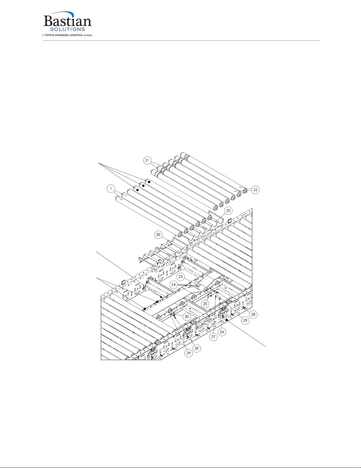
Figure 19: RZPAC Intermediate Bed Exploded View.............................................................................. 32
Figure 21: Screw Takeup Drive Belt Routing.......................................................................................... 36
Figure 22: Tension Indicators.................................................................................................................37
Figure 22: Belt Tracking by Adjusting Snub Rollers ................................................................................ 40
Figure 23: Chain Pitch Measurement ..................................................................................................... 51
Figure 24: Air Regulator Assembly.........................................................................................................62
Figure 25: General Arrangement, RZPAC Bed Section, Sheet 1 of 2...................................................... 70
Figure 26: General Arrangement, RZPAC Bed Section, Sheet 2 of 2...................................................... 70
Figure 27: General Arrangement, RZPAC Tail, Sheet 1 of 1................................................................... 70
Figure 28: General Arrangement, Belt Under Roller AC, Pneumatic Takeup Drive, Sheet 1 of 1............. 70
Figure 29: General Arrangement, Belt Under Roller AC, Screw Takeup Drive, Sheet 1 of 1.................... 70
List of Tables
Table 1: Reference Documents .............................................................................................................10
Table 2: Belt Hot Splicing Tools .............................................................................................................25
Table 3: Belt Hot Pressing Parameters .................................................................................................. 26
Table 4: Return Roller Positions for Intermediate Beds .......................................................................... 30
Table 5: Pneumatic Takeup Pressure Settings....................................................................................... 38
Table 6: Recommended Preventative Maintenance Schedule ................................................................ 42
Table 7: Fastener Standard Torque Values............................................................................................ 44
Table 8: Troubleshooting Guide.............................................................................................................63
Table 9: Standard Gearmotors with 1.250in Output................................................................................ 67
Table 10: Standard Gearmotors with 1.500in Output.............................................................................. 68
Table 11: RZPAC General Arrangement BOM ....................................................................................... 69

Installation and Maintenance Manual: RZPAC
Published November 2021
Rev. B
10
Reference Documents
Table 1: Reference Documents
MANUFACTURER
MANUAL
Bastian Solutions
Conveyor Director AC User Manual
Bastian Solutions
Side Cover and Guiderail Installation Manual
Bastian Solutions
Support Installation Manual
Bastian Solutions
RLCAC Installation and Maintenance Manual
Bastian Solutions
RLSAC Installation and Maintenance Manual
Habasit Holding
AG Habasit Fabric Conveyor Belts Installation and Maintenance Guide (6040)
ABB Motors and
Mechanical Inc Dodge Quantis RHB Installation and Maintenance Instructions (499322)
ABB Motors and
Mechanical Inc
Instruction Manual for DODGE® Setscrew, Eccentric Collar, D-Lok, H-E Series,
E-Z Kleen, Ultra Kleen and Food Safe Mounted Ball Bearings (MN3016)
ProCal
Innovations, LLC
(PCI)
INSTALLATION INSTRUCTIONS: XT®, QD®, HE & TAPERLOCK® BUSHINGS
(31905)

Installation and Maintenance Manual: RZPAC
Published November 2021
Rev. B
11
1 Introduction
Thank you for choosing Bastian Solutions Conveyor. The following manual serves as a guide for
installation, part replacement, and general maintenance for your material handling equipment. It is
important to read the manual and follow any instructions as it provides important safety information for
personnel and will maximize the longevity of the conveyor.
The information contained in this manual applies only to the products described. Uses, activities, or
processes related to installing or maintaining the equipment that are not explicitly described in this
manual are considered out of scope. Please contact Bastian Solutions Conveyor for any questions or
support that is not clearly addressed in this document. Bastian Solutions Conveyor is not responsible for
misuse of the equipment described in this manual or misuse of information in this manual. If you have any
questions, contact Bastian Solutions Conveyor Customer Service or Support at
ConveyorSupport@BastianSolutions.com.
2 OSHA and Safety
Bastian Solutions Conveyor is not responsible for ensuring that conveyors used in a system abide by
OSHA standards. Safety is of primary importance to our company, but as a product distributor we ask that
system integrators and end users conform with all applicable OSHA standards. We encourage that all
warnings in this manual are followed to avoid unnecessary risk.

Installation and Maintenance Manual: RZPAC
Published November 2021
Rev. B
12
3 Model: RZPAC
3.1 Overview
The Roller Zero Pressure AC (RZPAC) conveyor is designed for longer runs of zero pressure
accumulation, especially in applications where a combination of high speed and heavy product make DC
accumulation conveyor impractical. RZPAC uses a continuous belt under the conveying rollers driven by
an AC gearmotor motor, which is engaged and disengaged with the various conveying zones with
pneumatic actuators. Pneumatically driven brakes are used to stop the zones when the belt is
disengaged. A system of low voltage DC photoeyes and control cards senses product location and uses
solenoid valves to control the zones in any of several zero pressure control modes.
Figure 1: RZPAC Overview
3.2 Belt
The main conveying belt is 99mm wide and is available with two different joining options.
The laced belt is quick to install and quick to repair, and does not require special tools or expertise with
the lacing factory installed. It is well suited for any conveyors within its load capacity (light to medium
product loads, or heavy loads on shorter conveyors).
The hot-spliced belt requires special tools and skills to create splices, and cannot be installed or replaced
as rapidly due to the minimum time required for the splices to heat and cool. However, it is a more
durable option that is necessary for very heavy loads (working strength of the hot splice is about 2.7 times
the working strength of the lacing) and is maintenance-free for the life of the belt. The hot-spliced belt is
also quieter because there is no metal lacing contacting the conveying rollers.

Installation and Maintenance Manual: RZPAC
Published November 2021
Rev. B
13
3.3 Drive Section
Two different drive designs are available for RZPAC conveyors. The screw (fixed) takeup drive is the
least expensive option and is available for conveyor lengths up to 100 ft and total product loads up to
1050 lbs with a laced belt or 3200 lbs with a hot-spliced belt. Because the screw takeup drive is manually
tensioned, it requires periodic tension adjustment as the belt elongates. See Table 6: Recommended
Preventative Maintenance Schedule in section 6.2 for the required belt retensioning frequency.
The pneumatic takeup drive offers a low-maintenance automatic tension adjustment and a longer belt
takeup distance for conveyor lengths up to 200 ft, or heavily-loaded conveyors. Since the pneumatic
takeup automatically adjusts belt tension based on the conveyor load, it can handle heavier total product
loads, up to 1900 lbs with a laced belt or 4100 lbs with a hot-spliced belt.
Figure 2: Screw Takeup Drive Overview

Installation and Maintenance Manual: RZPAC
Published November 2021
Rev. B
14
Figure 3: Pneumatic Takeup Drive Overview
3.4 Tails
The RZPAC tail section is a 36” conveyor section that contains the tail pulley and a snub roller. The tail
sections are always placed as the first and last bed sections in an AC mark number. Rollers in the tail
section are banded together to transmit power from the zero pressure zone in the section to the rollers
above the tail pulley.
Optional power takeoff (PTO) timing pulleys may also be installed on a tail section, to drive an additional
conveyor section from the belt of the RZPAC conveyor.
Due to the nature of a PTO driven conveyor section, the driven conveyor cannot be
shut down without stopping the belt of the RZPAC conveyor, which will prevent
products on the RZPAC from advancing. Special attention is required to the system-
level control logic if a conveyor is to be driven from the infeed of an RZPAC conveyor. If
the RZPAC conveyor zones fill with product, any additional product entering the infeed
Installation and Maintenance Manual: RZPAC
Published November 2021
Rev. B
15
driven conveyor will cause a jam and shutdown of both the RZPAC and the infeed
driven conveyor that cannot be cleared without manually unloading the product.
3.5 Intermediate Beds
Intermediate beds contain one or more zero pressure zones and modules. An intermediate bed consists
of conveying rollers on the top, with pressure rollers mounted in modules below. The belt will be routed
between the conveying rollers and the pressure rollers during installation. One sideframe of the bed will
also contain all the cards, solenoids, and photoeyes, as well as the air and 24V DC electrical connections
that get installed along the full length of the conveyor. The brake modules will also be mounted on the
inside of this same sideframe. See Figure 4: RZPAC Intermediate Bed Exploded View for details.
Figure 4: RZPAC Intermediate Bed Exploded View
PRESSURE MODULE
SIDEFRAME
CONVEYING ROLLERS
PRESSURE ROLLERS

Installation and Maintenance Manual: RZPAC
Published November 2021
Rev. B
16
4 Receiving
Upon delivery of any Bastian Solutions conveyor, please review and check the following:
•The quantity of items received against the Bill of Lading.
•Complete a visual inspection of equipment to determine any damage that may have occurred
during shipping. If damage is present, document with pictures.
•Review Mark Number information and layout locations. More information can be found in
subsection 4.1.
If there are any missing or damaged components contact your Bastian Solutions Conveyor representative
with as much detail as possible. If you are unsure of your Bastian Solutions Conveyor representative,
please contact Customer Service at ConveyorSupport@BastianSolutions.com.
4.1 Mark Numbers
A mark number is a specific number given to a piece of equipment. A mark number is usually made up of
a single product line (RZPDC, RLVDC, BZPDC, etc.) but can contain many bed section lengths. They can
range from two inches to hundreds of feet. The mark number is used to help identify where the piece of
equipment will go within the system layout.
Every bed section of conveyor will have (2) stickers. One sticker on the infeed end of the bed, and one
sticker on the discharge end of the bed. Each sticker will contain the following information:
•BSC Project Number and Name
•Model Type
•Mark Number
•Match
•Piece
•Flow
Figure 5 shows stickers that would appear on an RZPDC that has two bed sections.
The match field on the stickers is used to indicate if two bed sections are to be spliced to one another. As
shown in Figure 5, the stickers where the two beds splice together both contain “Match: 1”. The piece
field defines the bed section number within the mark. The flow refers to the direction of product flow along
the conveyor system.
4.2 Skid Contents
Skids will contain varying combinations of conveyor sections, support structures, accessories, and
pertinent hardware. For protection of product integrity during shipping, accessories and supports may be
delivered on separate but labeled skids.
4.3 Skid Documentation
All shipments will contain a Bill of Lading for the delivery company, a skid label, and a skid manifest. Skid
labels have the contents of each shipped item located on the skid. Figure 6 shows a sample of a skid
label. These stickers are placed on the surface of each skid.
Figure 5: Mark Number Stickers

Installation and Maintenance Manual: RZPAC
Published November 2021
Rev. B
17
RZPAC conveyor may arrive in multiple skids for the same mark number. The number of skids shipped is
dependent on the OAW and OAL of the mark number.
Upon receiving the skid on site, please inspect for any visual damage of the equipment. If there are any
damages, please contact your BSC representative with images and details of the skid.
Figure 6: Skid Sticker

Installation and Maintenance Manual: RZPAC
Published November 2021
Rev. B
18
5 Installation
5.1 Layout
The installation supervisor on site should have the elevation and layout prints with detailed information
regarding the placement of conveyor sections and support structures. This information is not the
responsibility of Bastian Solutions Conveyor to provide unless otherwise specified.
1. Clear the workspace around the portion of the layout selected for installation.
2. Ensure that the conveyor and accessory skids containing the correct RZPAC mark number are
unpacked and all components are accounted for.
3. Measure out from the constrained origin to start placement of supports. It is recommended that
snap chalk lines are used, or other methods of keeping a consistent line.
A straight and level installation is crucial to proper belt tracking. The extra time spent
creating an accurate layout will more than pay for itself in time saved during belt
tracking and troubleshooting.
4. Use the elevation layouts to determine the top of conveyor surface and the incline/decline angle
of a mark section.
5. Place the support type that the layout designates.
6. Check the approximate height of each support and adjust if necessary. Final heights will be set
after the supports and conveyor are installed.
5.2 Setting the Conveyor
1. Check the flow direction on the mark stickers to ensure that conveyor is installed in the correct
order and that each section is facing the correct direction.
2. Starting from one end, place the conveyor onto the support structure and fasten with 3/8”-16
carriage bolts and serrated flange nuts.
3. Install a splice plate underneath each top flange at the bed break with 5/16”-18 hex bolts and
serrated flange nuts. Use the splice plate to align the mating sideframes vertically and
horizontally. See Figure 7: Floor Support and Splice Plate Installation.
4. Before moving on to the next section, torque the 5/16” splice plate fasteners to 17 ft-lb and the
3/8” floor support fasteners to 31 ft-lb.
Do not lift the drive section of the conveyor using the lifting lug on the AC motor and
gearbox. This will cause damage to the gearbox and drive pulley.
5. Check that the upstream and downstream heights of the conveyor section agree with the system
layout instructions and that the conveyor is leveled side-to-side.
6. Check that all floor supports are aligned with the chalk line or other layout mark to ensure that the
conveyor is straight.
7. Secure the supports to the floor (or other permanent fixture).

Installation and Maintenance Manual: RZPAC
Published November 2021
Rev. B
19
Figure 7: Floor Support and Splice Plate Installation
Refer to the “Bastian Solutions Conveyor Support Installation Manual” for more
information on installing conveyor.
5.3 Leveling and Straightening
1. Starting at one end, use a laser level or other accurate method to check the sideframe height at
each bed break on both sides of the conveyor, and adjust the supports as needed. All bed breaks
should be in the same plane and level side-to-side, +/- 1/16”.
2. Run a string line along the centerline of the conveyor, down its entire length, approximately 2”
above the rollers. Tension the string until it is freely suspended (not touching any rollers).
3. Measure the distance between the string and the edge of the sideframe at each bed break. The
distance should be the same at every bed break, +/- 1/8”. Adjust by loosening the support
anchoring bolts and sliding the entire floor support sideways if needed. The floor support
anchoring holes are slotted to allow some side-to-side adjustment. Re-secure the support once it
is in position.
5.4 Installing the Belt
1. Remove a few idler rollers near each tail, and approximately every 50 feet along the length of the
conveyor, as needed to pull the belt through. See section 6.7.4 for details.
2. Mount the roll of belting on a sturdy pole or axle, secured between the tines of a forklift or similar,
where the belting can be easily unrolled. Position the belt behind the tail of the conveyor nearest
the drive.

Installation and Maintenance Manual: RZPAC
Published November 2021
Rev. B
20
The belt should be installed with the shiny traction layer facing up towards the
conveying rollers and the textured or fabric side down towards the pressure rollers. For
belts with traction material on one side only, this orientation is important for correct
functionality. For belts with traction material on both sides, keeping the shiny layer
towards the conveying rollers will reduce noise.
3. Tape a thin piece of metal or stiff cardboard to the end of the belt to keep the end straight and
help guide it through the conveyor. Make sure the final thickness is less than 1/4”.
If the belt is prepared for a hot splice joint, it will have a small scrap of belting taped to
the end to protect the finger joint. Leave that piece of belting in place.
4. Once the belt reaches the other end of the conveyor, route it through the tail and pull the belt
through, leaving the return span hanging below the conveyor.
a. See Figure 8: Tail Belt Routing for belt routing through the tail.
b. Ensure that the return span of the belt is routed above any items (floor support cross
braces, conduits, etc.) that might cross underneath the conveyor.
5. Once the end of the belt reaches the drive, pull additional belt through until the roll is empty.
Position the end of the belt on the top of the conveyor in a convenient place to join the belt ends.
6. Route the belt through the drive. See sections 5.11.1 or 19 for belt routing, depending on whether
the conveyor uses a screw takeup or pneumatic takeup drive.
7. Route the belt through the second tail and bring the two belt ends together.
8. Remove tape from the belt.
9. See section 5.4.3 if the belt uses a hot spliced joint.
Figure 8: Tail Belt Routing
10. If the belt uses a laced joint, both ends should ship from the factory prepared with lacing.
a. Bring the two ends together and insert the lacing pin.
b. Trim the lacing pin approximately ½” to 1” longer than the belt on both sides.
c. Fold the end of the pin over and tuck it into the lacing on the upstream side of the belt.
Note that the belt moves opposite of product flow, so the upstream side of the belt is
Table of contents
Other Bastian Solutions Industrial Equipment manuals


Popular Industrial Equipment manuals by other brands


INVT
INVT Goodrive3000 Series Operation manual

Swift-Cut
Swift-Cut Swifty 1250 Installation and operation manual

Aventics
Aventics TC08 Assembly instructions

GEISMAR
GEISMAR TH 70 VLA Operation & maintenance instructions

Stahl
Stahl 8162 Series operating instructions

Southern States
Southern States EC-1V Installation instructions manual