SERIES DH151/DK151
SINGLE RANGE MONOCELLS
INSTRUCTION MANUAL D-131
8
Copyright 2023 - Revised, Comptrol All Rights Reserved
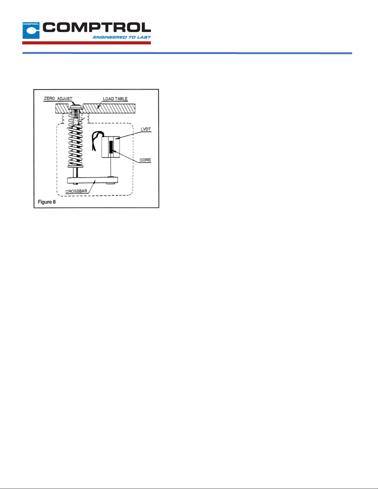
5.
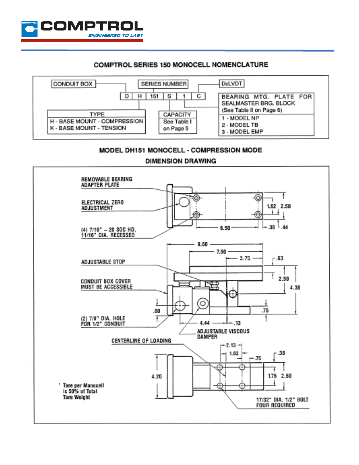
If the output is not zero, remove the dust cap located
on the load table to gain access to the zero
adjustment screw. (See Figure 8)
6.
Using a 7/64-inch hex key, turn the zero-
adjustment screw several turns counter clockwise
(CCW). Then, slowly turn the adjusting screw
clockwise (CW) until a zero reading is obtained on
the voltmeter. If the zero position is passed, turn
the adjusting screw counter clockwise (CCW) pass
the zero point. Then turn the adjusting screw back
in a clockwise (CW) direction until the meter reads
zero volt.
7.
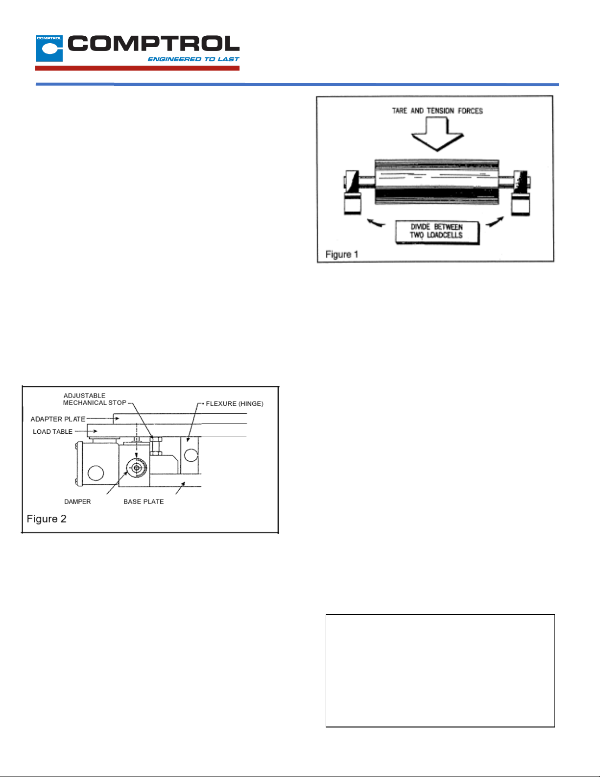
Deflect the Load Table of the loadcell by applying
pressure in the direction the tension force will be
applied. This may be done manually or with a
lever. A change in the output voltage signal should
be noticed.
NOTE: The polarity of the output signal will be
positive (+) for deflection in the Compression
Mode, and negative (-) for deflection in the Tension
Mode.
8.
Release the force applied to the Load Table should
allow the output signal to return to zero.
If the output signal does not return to zero, make
sure the measuring roll rotates freely. Check for
improper alignment of the measuring roll and for
friction or binding with the pillow block bearing.
Also check that the LVDT crossbar assembly is
free of any interference. Repeat Steps 1 through 8.
If the output signal still does not return to zero,
contact Comptrol.
9.
Repeat Steps 1 through 8 for the loadcell mounted
on the opposite end of the measuring roll.
II-H FULL LOAD ADJUSTMENT
After the loadcell has been zeroed, a pull test can be
made to check the output voltage of the loadcell at full
load. (See calibration sheet for voltage output)
1. Run a non-stretchable rope over the center of the
tension roll simulating the web path. (NOTE: the rolls
should be free to turn)
2. With one end of the rope secured, hang a known
weight, equally over the roll so that the total tension is
equal to the maximum strip tension specified on the
calibration sheet, at the other end. (See Figure 9A)
For larger tension where dead weights would be too
large, a crane scale can be used to simulate maximum
strip tension. (See Figure 9B)
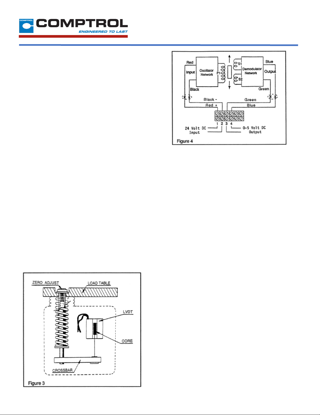
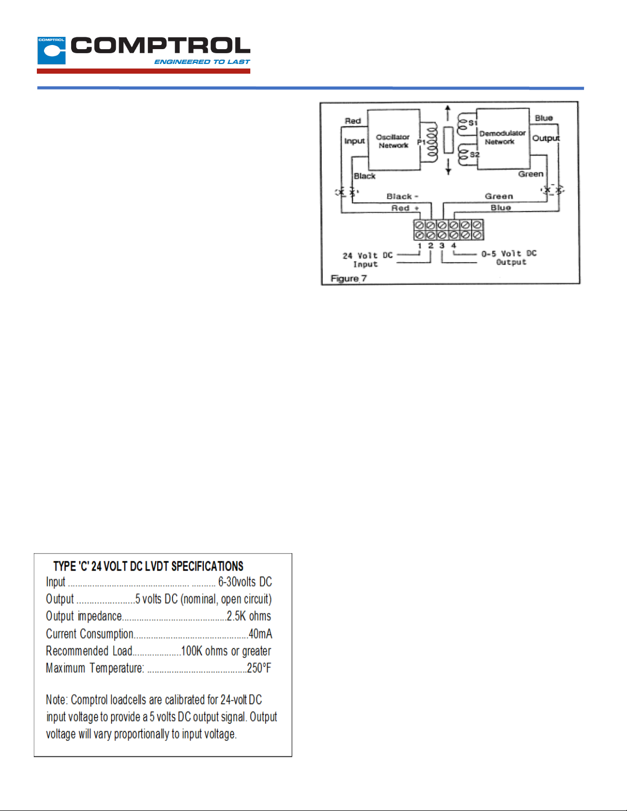
3. With a voltmeter connected to the bottom Terminals 3
and 4 of the Terminal Board, maximum output voltage
will be observed.
4. Repeat Step3 for the loadcell mounted on the opposite
end of the measuring roll.
5. Recheck to make certain that all leads are dressed
away from the LVDT crossbar assembly on both
loadcells and replace both conduit box covers.
Comptrol loadcells instrumentation provides the required
signal conditioning and a reliable high level output signal
for use as feedback control of a tension drive system.
The feedback signal is directly proportional to the strip
tension applied. If a Comptrol control is used, refer to the
control manual for further calibration.
Although the electrical output of Comptrol Monocells are
sufficient to drive most electrical indicators, substantial
signal conditioning is normally required for effective
tension instrumentation system control. Refer to the
documentation available from the instrumentation
supplier for more information.