Follett A36000 Guide

English Español Française
Installation, Operation and Parts Manual
After Service Number A36000
Ice Storage and Transport Systems
with SmartGATE® Ice Shield
208992R07
ITS1350-60
ITS3250-90
ITS2250-60
ITS700-31
801 Church Lane • Easton, PA 18040, USA
Toll free (877) 612-5086 • +1 (610) 252-7301
www.follettice.com
ITS500-31
ITS1700-90
Following installation, please forward this manual to the
appropriate operations person.
Order parts online
www.follettice.com

2
Contents
Welcome to Follett ..................................................................................................................... 3
Installation ................................................................................................................................. 4
Operation................................................................................................................................... 6
Cleaning .................................................................................................................................... 9

English
Welcome to Follett
Follett Ice Storage and Transport Systems enjoy a well-deserved reputation for excellent performance and long-
term reliability. To ensure that your equipment delivers this same degree of service, please read this manual
carefully before installing or operating the system. If you have questions during installation or operation of this
system, please call our technical service group at (877) 612-5086 or +1 (610) 252-7301.
Before you begin
After uncrating and removing all packing material, inspect the equipment for concealed shipping damage. If
damage is found, notify your shipper immediately and contact Follett Corporation for help in ling a claim, if
necessary.
Important cautions and operating rules
Read this manual completely before assembling or operating Ice Transport System
and follow cautions and instructions listed below.
To avoid damage to Ice Transport System and injury during operation:
• Do not move Ice Transport System once icemaker has been installed
• Anchor anged feet to oor as instructed on page 4
• Only use paddle provided to assist ice ow
• Only use cart to transport ice and reinstall carefully in bin bay when not in use
To avoid injury during operation of unit:
• Keep entire body clear of bin when breaking up ice
• Keep head and face away from paddle handle when breaking up ice
• Lock caster before scooping or shoveling ice from cart and when parked in bay
• Keep oor around Ice Transport System free of ice and water
• Always operate cart at a slow, reasonable speed
For best operation and to ensure delivery of clean, sanitary ice:
• Be sure bin system is level in both directions to provide proper drainage
• Position cart in bay before opening hopper door
• Install charcoal water lter on inlet water for icemaker
• Hang paddle implement in supplied bracket after each use
• Keep paddle clean and in good repair to avoid ice contamination
• Cover ice with cart lid when transporting
• Follow instructions in this manual for bin and cart cleaning and maintenance
• Drain melt water from cart when positioned in bay by opening drain valve
• Keep glass, dirt and other foreign objects out of bin and cart at all times
!
3

Installation
Uncrating cart
1. Remove paddle from skid by cutting plastic straps.
2. Cut strap holding front axle to skid.
3. Remove wheel chocks from skid at handle end of cart.
4. Roll cart(s) out of base section.
5. Remove tape holding lid to cart.
6. Remove lid storage bracket(s) from inside cart. (Brackets may be installed on left or right side of bin.
See Installing Bin section.)
Uncrating and installing base section
1. Remove screws holding anged feet and tie-down straps to skid and remove skid.
2. Remove packing material from inside of legs and around shutter door.
3. Position base in intended position and adjust feet to level unit in both directions.
4. Mark position of each anged foot anchoring hole.
5. Move base out of way and install anchors for 1/4" bolts in oor (supplied by others).
6. Reposition unit in intended position and anchor base unit to oor through anged feet.
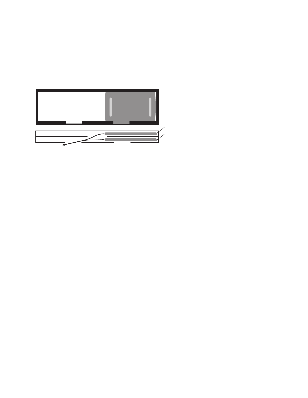
Installing bin
1. Remove 4 bolts fastening skid to underside of bin.
2. Remove all protective wrap from exterior.
3. Run 1/8" bead of supplied silastic in center of each gasket
band on base.
4. Install bin section on base section, taking care that locating
pins in base engage holes in bin.
5. Use fasteners provided to install paddle support bracket on
right or left side of bin in holes provided.
6. Remove paper from back of cart lid storage bracket(s) and position
brackets on side of bin.
7. Remove all tape and temporary fastenings from door assemblies
and outside of bin.
8. Mount icemaker(s) on top of bin in accordance with icemaker
manufacturer's instructions.
9. Install tie-down straps.
Installing tie-down straps
1. Remove screws from rivnuts on each side of bin section.
2. Reposition tie-down strap up until slot matches rivnut opening.
3. Reinstall screws in rivnuts and tighten.
When leveling, do not extend any leg more than 1" (26mm) for total leg height no greater than
2.125" (54mm).
Legs must be secured to oor through feet to avoid possible movement and resulting injury.
!
bin
section
base
section
locating pin
bead of
silastic
gasket gasket
bead of
silastic
4
Tie-down straps to secure bin to base are provided on each side of unit. Straps MUST be
installed to avoid possible injury should unit move. Bolt unit to wall for increased stability, and
bolt to oor to prevent side-to-side movement.
!

English
Sealing bin interior
1. Support shutter door(s) with one hand and remove thumbscrews from side of shutter door(s) at underside
of base.
2. Pivot door(s) downward to remove.
3. Gain access through this opening and seal entire perimeter of seam between bin and base with provided
sealant or equivalent.
4. After sealant has set but before shutter door(s) have been reinstalled, clean inside of bin following instructions in
this manual.
5. Reinstall shutter door(s).
Plumbing connections
Note: It is recommended that a full width grated oor drain be installed in front of bin.
1. Units are shipped for a right side exiting drain. To drain to left, switch positions of screws in trough brackets
from lower hole to upper hole on left bracket and upper hole to lower hole on right bracket.
2. Remove plug from left side of drain trough and insert in right side.
3. Connect drain line to 1 1/4" PVC slip t drain tting.
4. Make nal connections to icemaker.
Affixing operating labels
Operating labels taped to base front educate staff to shutter door operation. If desired, these labels can be affixed
permanently by peeling off back paper and affixing in locations desired.
Note: Adhesive backing is extremely strong and labels cannot be easily removed once installed.
Removing lower door assembly
(only if required for access through narrow doors)
1. With lower access door closed remove Phillips
head screw and washer from hinge area on each
side of lower access door.
2. Insert screwdriver between door and hinge bracket
on one side of door and gently push against bracket
to provide room for door stud to clear bracket.
3. Remove access door.
4. Pull up on SmartGATE to remove.
5. Remove three or four (3 or 4) screws along top of
door assembly.
6. Pull forward on assembly and remove.
5
Use sealant provided to seal entire
perimeter of seam where base and
bin section join.
The joint between base and bin sections must be sealed with silastic to prevent leakage and/
or ice contamination and potential voiding of warranty. One or more shutter doors may need
to be removed to seal bin.
!
bin
section
base
section
interior
exterior
completely
seal gasket
access
door
SmartGATE
lower door
assembly
Cross section of ITS sections joined

Reinstalling door assembly
1. Reinstall lower door assembly in bin opening.
2. Reinstall three or four (3 or 4) screws in hood at top of door assembly.
3. Reinstall SmartGATE in side panel tracks and push down to seat.
4. With door closed insert one door stud through hinge bracket.
Note: For proper operation the access door must be reinstalled in the closed position.
5. On other side, insert screwdriver between door and hinge bracket and gently push against bracket to provide
room for door stud to clear bracket.
6. Reinstall washers and screws in lift door and tighten.
7. Check door to ensure proper operation.
Ice guide adjustment
Some ice types are very “slippery” and may ow over sides of cart when exiting hopper. Ice guides hang down below
hopper and help contain owing ice inside cart.
Guides are installed in highest position at factory, providing 3/4" clearance to top of cart when legs are in full
down position. If legs are adjusted up during leveling of Ice Transport System, ice guides should be lowered to
maintain 3/4" (19mm) clearance. Access to sides of Ice Transport System is required to perform operation.
To reposition ice guides after legs have been adjusted:
1. Position cart (with totes, if so equipped) in bay below shutter door opening.
2. Determine amount guides must be lowered to maintain 3/4" (19mm) clearance.
3. Remove thumbscrews holding guides.
4. Select hole to reposition guide at proper level and resecure with thumbscrew.
5. Repeat process for each bay in system.
Operation
Cart drain operation
1. Position cart all the way in bay.
2. Lock caster to prevent cart movement.
3. To open drain, pull knob out.
4. To close, push knob in.
Cart lids
1. Hang cart lids on brackets on bin side when carts positioned in bay.
2. Remove from bracket and place lid on cart when transporting ice.
3. To avoid placing lid on oor, position lid horizontally on cart lip, resting lid against cart handle when unloading ice
from cart.
4. Reinstall lid in bracket on side of bin before placing cart in bay.
6
PUSH TO CLOSE
brackets on underside of hopper to which
ice guides are secured

English
7
2
1
3
1
2
2
1
3
1
Pushing cart into bay
1. PUSH cart all the way to back.
2. PULL cart drain open.
3. Lock brake on caster DOWN.
Loading ice
1. PULL shutter handle open.
2. Store handle up against bin.
Pulling cart out
1. PUSH shutter handle closed.
2. PUSH cart drain closed.
3. Release brake on caster.
Transporting ice
1. PULL cart from base.
2. Place lid on cart.
Ice Transport System operation
B
CD
A

Breaking ice bridges
It may be necessary to use the paddle to break up ice bridges that occur along the sides and in the middle of the bin.
This often happens if ice has been held in storage for a period of time without use. Use supplied paddle accessory to
break up bridges.
1. Completely knock down all ice from sides and back of bin.
2. Knock down any bridge that has occurred in middle.
3. Agitate paddle back and forth to break up congealed ice mass.
SmartGATE operation
SmartGATE can be adjusted and locked at one of several levels to accommodate ow characteristics of different
types of ice.
Bin is shipped with SmartGATE in full down position. SmartGATE can be raised and locked in higher position for
better ow or when more access is needed.
Do NOT dig up at ice. Instead, break away “legs” that are holding bridges. Ice above will
then fall.
To avoid injury, do not attempt to break up bridged ice through upper windows or hopper
shutter door. A falling ice bridge can cause paddle to lift. Keep head and face away from
paddle handle to avoid injury.
!
8

English
9
Cleaning
Bin drain system cleaning
1. Remove upper tray(s) and wash with cleaning solution, rinse and reposition in brackets.
2. Saturate a cloth with cleaning solution and insert through a loop in end of a piece of wire.
3. Feed wire through vertical drain tube, and pull wire and cloth through tube.
4. Pour 1 gallon (4L) hot water into lower drain trough.
Drain tray cleaning
1. Remove two thumbscrews on side of drain tray and pull drain tray forward to remove.
2. Wash with an approved cleaner.
Shutter doors and rails
1. Support hopper shutter door with one hand and remove thumbscrews from side of hopper shutter door at under
side of base section.
2. Pivot door down to remove.
3. Wash door, rinse thoroughly and sanitize.
4. Remove thumbscrews holding front and rear of shutter tracks.
5. Wash tracks, rinse thoroughly and sanitize.
Cart and cart drain system
1. Wash cart liner with an approved cleaner.
2. Rinse and sanitize.
Cleaning bin before use and ongoing bin maintenance
Interior of bin must be cleaned and sanitized prior to use and should be cleaned on routine basis during use
(see next page).
Clean and sanitize bin and cart(s) interiors prior to use and on regular schedule as
needed. Use non-chlorine based cleaner and sanitizer suitable for use in a food zone. Do
NOT use chlorine-based cleaners, which can cause staining and pitting of stainless steel
components. Do not run Totes through a dishwasher. Turn off icemaker(s) and remove ice
from bin before beginning.
!

Interior bin care
Follett ice storage bins with SmartGATE are equipped with polyethylene liner walls which should be cleaned and
sanitized periodically with Ecolab Mikro-chlor Cleaner or any product suitable for use in a food zone.
Important: Follett Corporation recommends installing a properly-sized, activated carbon (charcoal) water lter
on water supply to icemaker to remove chlorine.
1. Remove upper inspection windows by sliding windows to one side. Grasp the end of the front window and pull
toward you as the window is slid to the opposite side. Repeat for rear window.
2. Wash bin walls, hopper, access door plate and partition (if any), rinse and sanitize.
Exterior bin care
Exterior stainless steel surfaces can be cleaned with a stainless steel cleaner such as 3M Stainless Steel Cleaner &
Polish or equivalent.
Technical assistance available toll free
Should you have any questions concerning installation or maintenance of Follett ice storage bins, please call our
technical service department at (877) 612-5086 or +1 (610) 252-7301 between 8 a.m. and 5 p.m. Eastern time.
10
rear window
front window

English
Reference # Description Part #
1 (2) Inspection window, 21.125"W x 8.625"H (2 used per bin) - 3250/2250 502237
Not shown (2) Inspection window, 12.5"W x 9"H (2 used per bin) - 500 502264
2 Frame assembly, lower door, 45" (includes 502177 & 502182) 502361
Not shown Frame assembly, lower door, 28" (includes 502176 & 502181) 502365
3 Door, outer lift, 45" (includes 502178 & 502179) 502177
3 Door, outer lift, 28" (includes 502178 & 502179) 502176
4 Hinge, RH door mount (includes hardware) 502179
5 Hinge, LH door mount (includes hardware) 502178
6 Ice Gate, 40", w/o holes 502182
6 Ice Gate, 24", w/o holes 502181
7 Catch, Ice Gate 502185
8 Hinge bracket, bin mount, LH/RH, (pair, includes hardware) 502180
Not shown Strap, hold down 502214
9 Foot, anged (1), bolt base 502196
10 Bracket, ice paddle 502064
11 Paddle, ice 502063
Not shown Shovel, ice 501796
Not shown Bracket, ice shovel 502360
Replacement parts
1
3
4
2
8
6
7
8
5
11
9
10
11
Order parts online
www.follettice.com

Reference # Description Part #
1 Drain pan upper – includes (2) 501100 502847
2 Vertical drain tube 502848
3 Bumper, and stud – includes 502865 502849
4 Bracket, lower drain trough 502850
5 Drain tting, vertical drain tube to lower trough 502851
6 End cap, lower drain trough 502852
7 Drain trough – includes (2) 502852 (single bay – ITS500, ITS700) 502853
7 Drain trough – includes (2) 502852 (double bay – ITS1350, ITS2250) 502854
7 Drain trough – includes (2) 502852 (triple bay – ITS1700, ITS3250) 502855
8 Cap, bumper 502865
9 1" MPT x 1" barb 90° tting 00148965
10 Drain assembly 206011
3
5
7
4
Drain system
12
1
2
4
3
5
7
3
1
3
3
6
6
4
8
Order parts online
www.follettice.com

English
Reference # Description Part #
1 Track, shutter door – includes (2) 502272, (8) 501100 502864
2 Thumbscrew, 10-32 X 1/2" 501100
3 Bearings (2), shutter door, nylon 11-7/16" – includes (4) 501100 502269
4 Shutter door – (includes 502857 and (2) 502272) 502856
5 Shutter door, handle assembly – includes 502858 502857
6 Rod handle, shutter door – includes (2)502859 502858
7 Spacer, bearing – includes 501100 502272
8 Screw, shutter handle rod 502859
9 Shoulder screw, handle shutter door 502860
10 Cover, joint, two and three bay, blue hopper 00112821
Not shown Ice guide – includes (2) 501100 502861
Not shown Bracket, ice guide – includes (2) 501100 502863
1
5
2
3
1
4
2
7
10
Shutter door assembly
Multi-bay joint cover
13
3
9
6
8
9
4
7
Order parts online
www.follettice.com

Reference # Description Part #
All Drain assembly (includes entire assembly shown) 502021
1 Vent plug 502106
2 O-ring, drain assembly 502022
3 Rod, drain (includes 502061 plate drain support) 502217
4 Knob, drain 502029
5 Retaining bushing 502289
6 Fitting, drain assembly 501743
Side view – cart Bottom view – cart
1
2
6
4
3
5
Cart
1
2
3
4
Reference # Description Part #
1 Lid 501744
2 Caster, swivel, locking, (includes mounting bolts & lock washers) 502529
Not shown Bushing, 8" wheel, Rhombus 502531
3 Wheel, 8", xed (includes 2 cotter pins & 2 washers) 502530
4 Axle, 24.125" (includes 2 cotter pins & 4 washers) 502332
5 Strap, axle (2 required per axle) 502028
6 Plate, drain support 502061
Not shown Bracket, lid holder 502055
Not shown Ice removal Tote (1) 502263
Not shown Handle, Tote 502097
Not shown Washer, axle 502230
Not shown Cotter pin 502040
Cart drain
5
5
6
14
Order parts online
www.follettice.com

English
15
This page intentionally left blank.

801 Church Lane • Easton, PA 18040, USA/EE.UU/États-Unis
Toll free (877) 612-5086
Phone/ Teléfono / Téléphone: +1 (610) 252-7301 208992R07
4/18
SmartGATE is a registered trademark of Follett Corporation, registered in the US.
SmartGATE es una marca comercial de Follett Corporation registrada en los EE.UU.
SmartGATE est une marque de commerce déposée de Follett Corporation enregistrée aux États-Unis.

English Español Française
Manual de instalación, uso y piezas
Para modelos a partir del A36000
Sistemas de almacenamiento y transporte
de hielo con placa de ujo SmartGATE®
208992R07
ITS1350-60
ITS3250-90
ITS2250-60
ITS700-31
801 Church Lane • Easton, PA 18040, EE.UU.
Teléfono: +1-610-252-7301
www.follettice.com
ITS500-31
ITS1700-90
Tras su instalación, entregue este manual a la persona encargada
del funcionamiento de este equipo.
Pida sus piezas en internet
www.follettice.com

Indice
Instalación ................................................................................................................................. 4
Funcionamiento ......................................................................................................................... 6
Limpieza .................................................................................................................................... 9
Piezas.......................................................................................................................................11
2

Español
Bienvenidos a Follett
Los sistemas de almacenamiento y transporte de hielo de Follett cuentan con una bien ganada reputación por su
excelente rendimiento y su gran abilidad a largo plazo. Para asegurarse de que su equipo ofrezca el mismo nivel de
servicio, lea detenidamente este manual antes de instalar o poner en funcionamiento el sistema. Si tiene cualquier
pregunta durante la instalación o funcionamiento de este sistema, llame a nuestro equipo de servicio técnico al
+1-610-252-7301.
Antes de empezar
Después de sacar todo el contenido de las cajas y retirar el material de empaque, inspeccione el equipo para
determinar si hubo algún daño invisible durante el envío. Si encuentra algún daño, notique al transportista
inmediatamente y contáctese con Follett Corporation para ayudarle a llenar un formulario de reclamo, si es
necesario.
Precauciones importantes y normas de funcionamiento
Lea detenidamente todo el manual antes de montar o accionar el Sistema
de transporte de hielo y siga las precauciones e instrucciones indicadas a
continuación.
Para evitar daños en el Sistema de transporte de hielo y accidentes durante su uso:
• No mueva el sistema de transporte de hielo una vez instalado la unidad fabricadora de hielo.
• Fije los pies de la unidad al suelo tal y como se indica en la página 4.
• Utilice únicamente la pala suministrada para ayudar al trasvase del hielo.
• Utilice únicamente el carrito para transportar el hielo y colóquelo con cuidado en el espacio
reservado para el carrito bajo el depósito cuando no lo utilice.
Para evitar accidentes durante el funcionamiento de la unidad:
• Mantenga su cuerpo alejado del depósito mientras retira el hielo acumulado.
• Mantenga la cabeza y el rostro alejados del mango de la pala mientras retira el hielo acumulado.
• Bloquee las ruedas antes de retirar hielo del carrito cuando se encuentre en en el espacio reservado
para el carrito bajo el depósito.
• Mantenga el suelo que rodea al sistema de transporte de hielo libre de agua y hielo.
• Utilice siempre el carrito a una velocidad lenta y razonable.
Para el mejor funcionamiento y para obtener hielo limpio e higiénico:
• Asegúrese de que el sistema del depósito está nivelado en ambas direcciones para lograr un
vaciado adecuado.
• Coloque el carrito en el espacio reservado para el carrito bajo el depósito antes de abrir la
compuerta de salida.
• Instale el ltro de agua y carbón vegetal en la entrada de agua de la máquina de hacer hielo.
• Deje colgada la pala en el soporte suministrado después de cada uso.
• Mantenga la pala limpia y en buen estado para evitar la contaminación del hielo.
• Cubra el hielo con la tapa del carrito durante el transporte.
• Siga las instrucciones de este manual para la limpieza y mantenimiento del depósito y del carrito.
• Retire el agua proveniente del hielo fundido del carrito cuando esté en el espacio reservado para el
carrito bajo el depósito, mediante la apertura de la válvula de vaciado.
• Mantenga el cristal, la suciedad y otros objetos extraños alejados del depósito y del carrito en
todo momento.
!
3

Instalación
Desembalaje del carrito
1. Retire la pala del soporte cortando las tiras de plástico.
2. Corte las tiras que sujetan el eje delantero al soporte.
3. Quite las cuñas de las ruedas del soporte, en el extremo del asa del carrito.
4. Saque el/los carrito(s) de la sección base.
5. Retire la cinta adhesiva que sujeta la tapa al carrito.
6. Retire los soportes de almacenamiento de la tapa del interior del carrito (los soportes pueden instalarse en el
lado izquierdo o derecho del depósito. Véase la sección Instalación del depósito).
Desembalaje e instalación de la sección base
1. Quite los tornillos que sujetan los pies y las grapas metálicas de sujeción al soporte, y retire el soporte.
2. Retire el material de embalaje del interior de las patas y alrededor de la compuerta.
3. Coloque la base en su posición y ajuste los pies para nivelar la unidad en ambas direcciones.
4. Marque la posición de los oricios de anclaje de cada pie.
5. Retire la base de su posición y coloque anclajes para tornillos de 6 mm en el suelo (suministrados por
terceros).
6. Vuelva a colocar la unidad en su posición y je la unidad base al suelo mediante los pies de jación.
Instalación del depósito
1. Quite los 4 pernos que sujetan el soporte a la parte inferior del
depósito.
2. Retire el envoltorio protector del exterior.
3. Coloque una tira de 3 mm de sellador de silicona (Silastic) en el
centro de cada banda de juntas de la base.
4. Coloque la sección del depósito sobre la sección base, con
cuidado de colocar los pasadores de la base encarados con los
oricios del depósito.
5. Utilice los elementos de jación suministrados para instalar el
soporte de la pala en el lado izquierdo o derecho del depósito, en
los oricios realizados a tal n.
6. Retire el papel de la parte trasera de los soportes de
almacenamiento de la tapa del carrito y coloque los soportes en
el lateral del depósito.
7. Quite toda la cinta adhesiva y las jaciones temporales de las
compuertas y del exterior del depósito.
8. Monte las unidades de fabricación de hielo en la parte superior
del depósito, de acuerdo con las
instrucciones del fabricante de las unidades de fabricación de hielo.
9. Coloque las grapas metálicas de jación.
Instalación de las grapas metálicas
1. Quite los tornillos de cada lado de la sección del depósito.
2. Vuelva a colocar la grapa metálica de jación hasta que las ranuras coincidan con las aperturas laterales.
3. Vuelva a colocar los tornillos y apriételos.
Al nivelar, no extender ninguna pata más de 26 mm para que la altura total de las patas no
supere las 54 mm.
Las patas deben jarse al suelo a través de los pies para evitar posibles movimientos que
puedan provocar accidentes.
!
Depósito
base
Pasador de
ubicación
Ti
ra de sellador
de silicona
Junta Junta
Ti
ra de sellador
de silicona
4
Coloque las grapas metálicas de jación para asegurar el depósito a la base en cada uno
de los lados de la unidad. Las grapas metálicas DEBEN instalarse para evitar posibles
accidentes por movimiento de la unidad. Fije la unidad a la pared con pernos para aumentar la
estabilidad, y al suelo para evitar los movimientos laterales.
!
This manual suits for next models
8
Table of contents
Languages:
Other Follett Storage manuals
Popular Storage manuals by other brands

Long Island Technology Group
Long Island Technology Group BFW BayPort operating manual

Regulus
Regulus DUO N PR Installation and operation manual

Seagate
Seagate ST34502LW/LC installation guide

Panasonic
Panasonic RP-SDUC64GAK operating instructions

Rocstor
Rocstor COMMANDER-X user manual

Panasonic
Panasonic UB-5335 manual