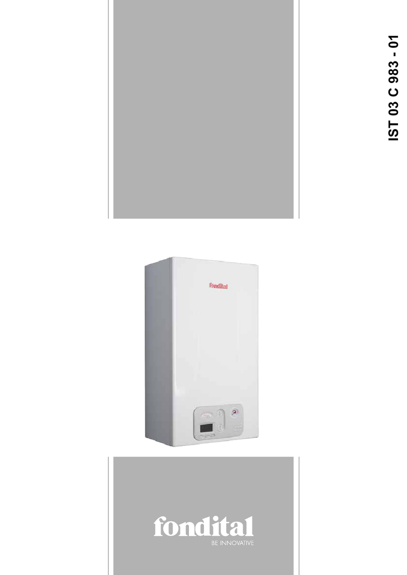
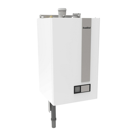
Fondital ELBA DUAL 23 Quick start guide


This manual suits for next models
5
Table of contents
Other Fondital Boiler manuals

Fondital
Fondital CAPRI C Operation instructions
Fondital
Fondital ITACA RTFS 24 User manual
Fondital
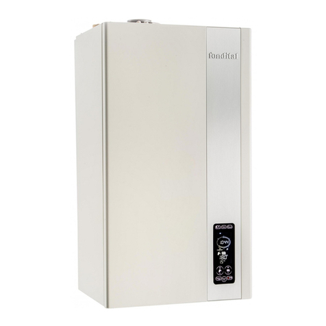
Fondital PANAREA COMPACT User manual
Fondital
Fondital ITACA CTFS 24 Installation and operating instructions

Fondital
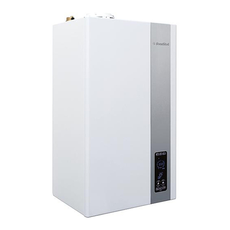
Fondital MAUI KR 115 User guide
Fondital
Fondital FORMENTERA KC 24 User manual

Fondital
Fondital FORMENTERA KC 12 Quick start guide

Fondital
Fondital FORMENTERA CTN 24 Quick start guide

Fondital
Fondital Nova Florida DELFIS CTFS 24 AF User manual

Fondital
Fondital Nias Dual BTFS 24 User manual

Fondital
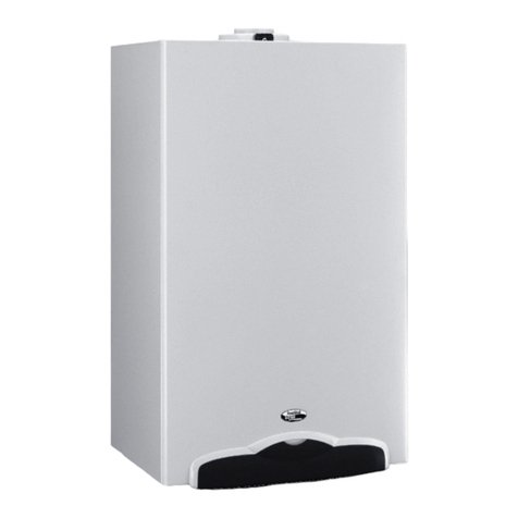
Fondital Antea 24kW Range Quick start guide
Fondital
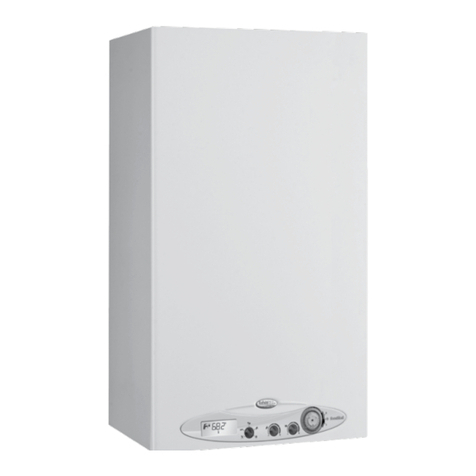
Fondital ITACA KC 24 Quick setup guide
Fondital
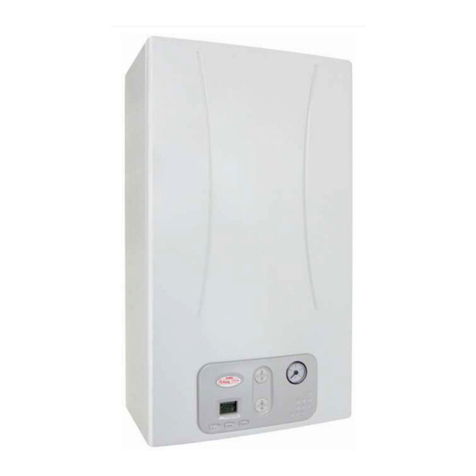
Fondital Tahiti Condensing 24 kW Combi (KC) Quick start guide
Fondital
Fondital ANTEA CTFS 13 AF Quick start guide

Fondital
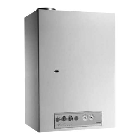
Fondital MADEIRA SOLAR COMPACT KBS 24 Installation and operating instructions
Fondital
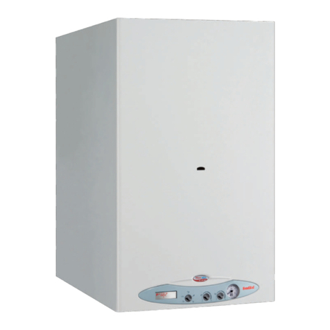
Fondital NIAS series Quick start guide
Fondital
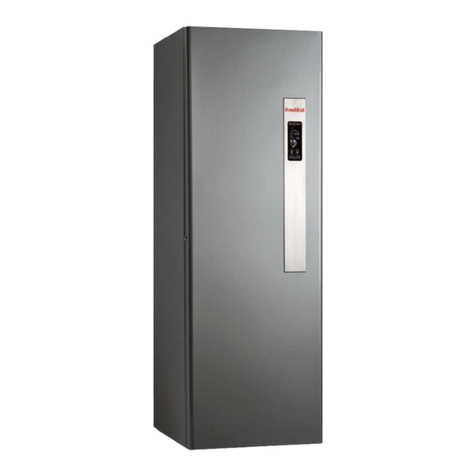
Fondital Nias Dual Line Tech BTN 24 Quick start guide
Fondital
Fondital MADEIRA SOLAR KRBS 12 Quick start guide
Fondital
Fondital ITACA KB 24 Quick start guide
Fondital
Fondital minorca rc User manual
Popular Boiler manuals by other brands

SAS
SAS Agro Eco Operation and Maintenance Documentation
Baxi
Baxi NUVOLA DUO-TEC GA Series Instruction manual for users and fitters
Riello
Riello RESIDENCE COLONNA CONDENS SOLAR KV/200 - 30... Installation and maintenance manual
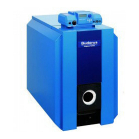
Buderus
Buderus Logano G215 US Installation and maintenance instructions
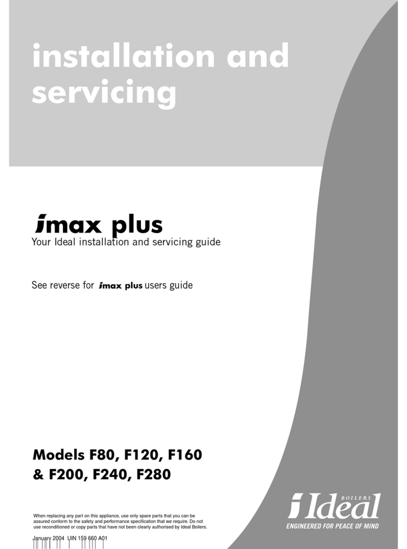
IDEAL
IDEAL imax plus F80 Installation and servicing

Thermona
Thermona THERM EL 5 Operation and maintenance manual

Sime
Sime Planet AquaQuick 25 BF Installer's instructions

Potterton
Potterton Performa 24 Installation and servicing instructions

Slant/Fin
Slant/Fin VICTORY II VHS Series User's information manual
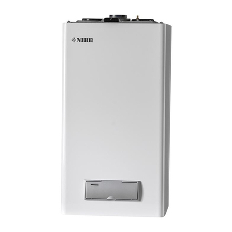
Nibe
Nibe NIBE GBM 10-15 installer and user manual

DAXOM
DAXOM Navidens 50 user manual
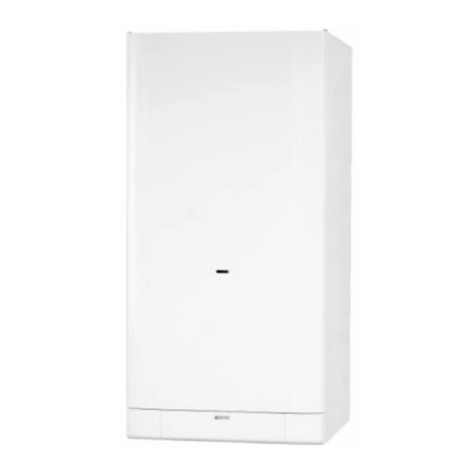
Biasi
Biasi Delta User manual and installation instructions

STOKVIS ENERGY SYSTEMS
STOKVIS ENERGY SYSTEMS ECONOFLAME R2000 Installation, operation & maintenance documentation
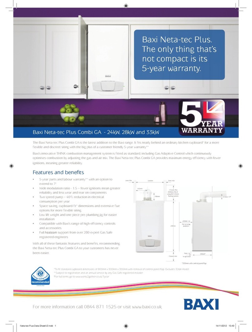
Baxi
Baxi Neta-tec Plus Features and specifications

BRAVILOR BONAMAT
BRAVILOR BONAMAT HWA 20 operating instructions
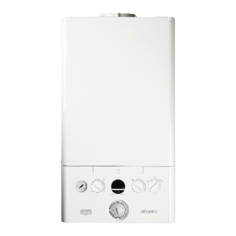
Ideal Boilers
Ideal Boilers Atlantic 24 Installation & servicing instructions

Lincat
Lincat EB3HC Installation, operating and service instructions

Slant/Fin
Slant/Fin VICTORY II VHS Series User's information manual

