ADDING A SCENE TO A SPECIFIC STEP IN A CHASE
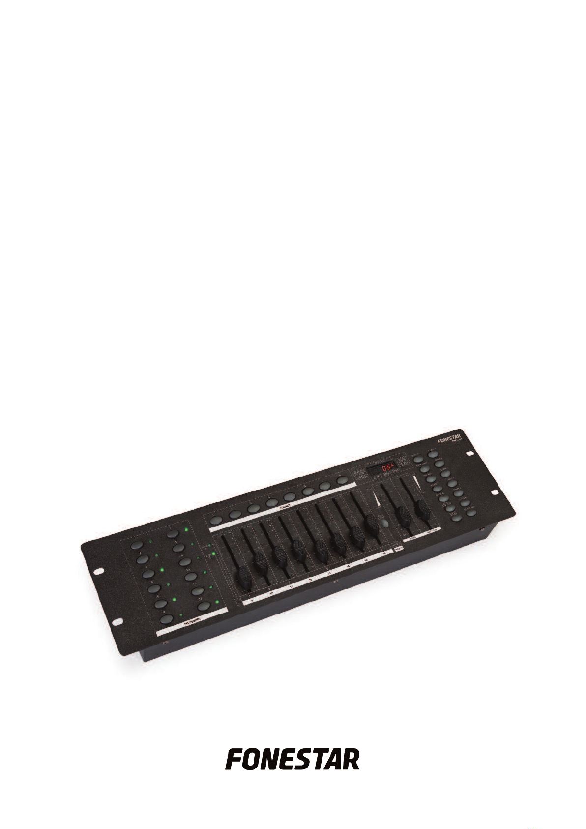
-Hold down the PROGRAM button for 3 seconds to access the programming mode. The LED PROGRAM
indicator will flash constantly.
- Select the chase to be edited using the CHASE 1-6 buttons.
- Press the TAPSYNC/DISPLAY button and the total number of scenes will appear on the display.
- Find the required position for the new scene using the BAN UP and BAN DOWN buttons.
- Press the MIDI/ADD button to add a blank scene where the new scene will be stored.
- Select the bank where the scene is that you wish to add to the chase using the BAN UP and BAN DOWN
buttons.
- Press the corresponding SCENES 1-8 scene and then press the MIDI/ADD button to store the
programming. All the LED indicators will flash 3 times to show that it has been programmed correctly.
- Repeat the previous steps to add all the scenes you wish to the chase.
- Press and hold the PROGRAM button for 3 seconds to exit the programming mode and press the
BLAC OUT button to activate the output channels again.
Example: to store the new scene between two specific positions, for example between 5 and 6, you have
to press the MIDI/ADD button when the display shows scene 005. On pressing this button, the display will
show the number of the empty scene, increasing it one unit, so in our case it will say 006, showing that the
empty scene has been created afterwards and between positions 5 and 6.
ADDING A BAN TO THE END OF A CHASE
- Hold down the PROGRAM button for 3 seconds to access the programming mode. The LED PROGRAM
indicator will flash constantly.
- Select the chase that you wish to edit using the CHASE 1-6 buttons.
- Select the bank that you wish to add to the chase using the BAN UP and BAN DOWN buttons. Take into
account that the 8 scenes from the bank will be stored at the end of the current chase programming.
Press the MUSIC/BAN COPY button to make a copy of the bank.
- Press the MIDI/ADD button to store the programming in the chase. All the LED indicators will flash 3 times
to show that it has been programmed correctly.
- Repeat the previous steps to add all the banks you wish to the chase.
- Press and hold the PROGRAM button for 3 seconds to exit the programming mode and press the
BLAC OUT button to activate the output channels again.
DELETING A SCENE FROM A CHASE
- Hold down the PROGRAM button for 3 seconds to access the programming mode. The LED PROGRAM
indicator will flash constantly.
- Select the chase that you wish to edit with the CHASE 1-6 buttons.
- Press the TAPSYNC/DISPLAY button and the total number of scenes will appear on the display.
- Find the scene to be deleted using the BAN UP and BAN DOWN buttons.
- Press the AUTO/DEL button to delete the scene. All the LED indicators will flash 3 times to show that the
scene has been deleted correctly.
- Repeat the previous steps to delete as many scenes as you wish.
- Press and hold the PROGRAM button for 3 seconds to exit the programming mode and press the
BLAC OUT button to activate the output channels again.
- 10 -
EN