FONICA INTERNATIONAL FLAG Quick start guide

www.fonicainternational.com
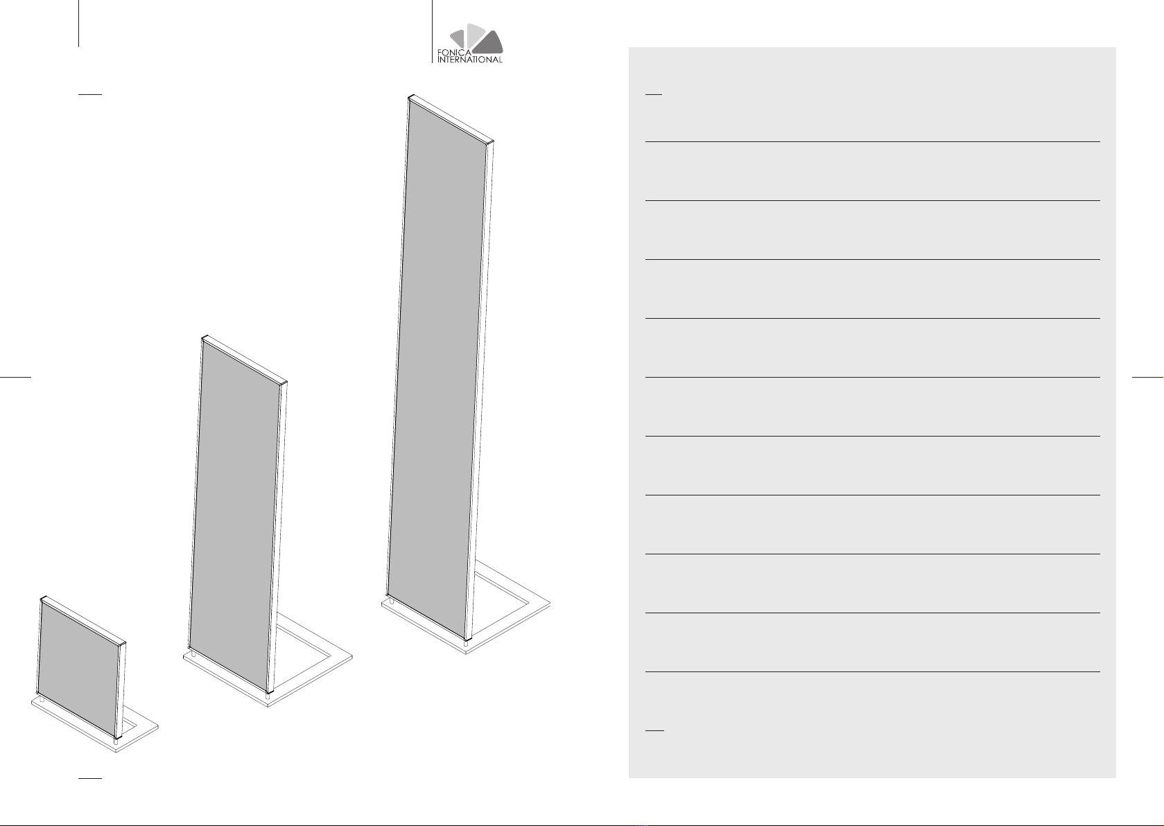
FLAG ISODYNAMIC SPEAKERS
INSTALLATION AND USE
1 / WARNINGS
4 / POSITIONING IN THE LISTENING ROOM
2 / PACKAGING CONTENTS
5 / SPEAKERS CONNECTIONS
3 / ASSEMBLY INSTRUCTIONS
6 / REMOTE CONTROL
7 / LED INDICATORS ON THE BACK PANEL
8 / TECHNICAL SPECIFICATIONS
9 / CLEANING AND MAINTENANCE
10 / WARRANTY ACTIVATION
11 / ASSISTANCE
www.fonicainternational.com
FLAG ISODYNAMIC SPEAKERS
32
www.fonicainternational.com www.fonicainternational.com
FLAG ISODYNAMIC SPEAKERS
54
FLAG ISODYNAMIC SPEAKERS
1 / WARNINGS
• For any assistance intervention, please contact qualified personnel.
• To safely proceed with the assembly and installation of the M and L model, we recommend
the assistance of a second person.
• Do not expose the speakers to dripping or splashing and do not place objects containing
liquids above it.
• Do not place the speakers near heat sources, in humid or too cold environments.
• Temperature of use: from 10 to 35°C.
• Do not expose the device to direct sunlight.
• Keep the device away from sharp objects and objects that may be attracted to magnets.
[ACTIVE VERSIONS ONLY]
CAUTION RISK OF ELECTRIC SHOCK!
Do not open the device for any reason, even if disconnected
from the mains.
CAUTION!
It is important to avoid touching the speaker’s part covered
with fabric. Below it there is the speaker’s membrane which
may be damaged by contacting with foreign objects. Please
keep in mind, when you need to move the speaker, to always
hold the profile’s perimeter, without touching the fabric.
Always handle and move the speaker holding the perimeter
profile without touching the fabric. Always use the perimeter
profiles without taking them off. They must not be pulled as
they could come off.
CAUTION!
Under the entire surface of the fabric there are powerful ma-
gnets and a delicate membrane therefore this surface must
never impact with any type of stuff or being put beside ma-
gnets or ferromagnetic objects that could be attracted to the
speaker’s surface.
CAUTION!
The speaker, if correctly installed on its base, is in firm ba-
lance. Slight fluctuations of the panel are usual. Do not lean,
push or modify its balance in any way, as it may cause the
falling or the overturning of the device.
FONICA INTERNATIONAL S.R.O. does not assume responsi-
bility for any damage caused to people and/or things due to
assembly and/or an incorrect use of the speaker.
CAUTION!
This speaker is intended for exclusive use together with its
supplied stand and installed according to the instructions.
The use of the speaker with other supports can lead to pro-
duct instability and cause injury.
CAUTION!
Loudspeakers in the active, powered version require a stable
ground connection. Verification of the earth connection in the
power socket where the equipment is connected by a quali-
fied person is required. The active loudspeaker must be con-
nected to the protective earth conductor of the system throu-
gh the power cable connected to an earthed power socket.
This socket must be easily accessible after the installation of
the loudspeakers. The part of the cables inside the equipment
that connect the power connector to the switch remains ener-
gized even after the switch is opened.
Never open or disassemble parts of the loudspeakers: they
contain dangerous parts and can irremediably compromise
the safety and functioning of the loudspeakers.

www.fonicainternational.com www.fonicainternational.com
FLAG ISODYNAMIC SPEAKERS
76
FLAG ISODYNAMIC SPEAKERS
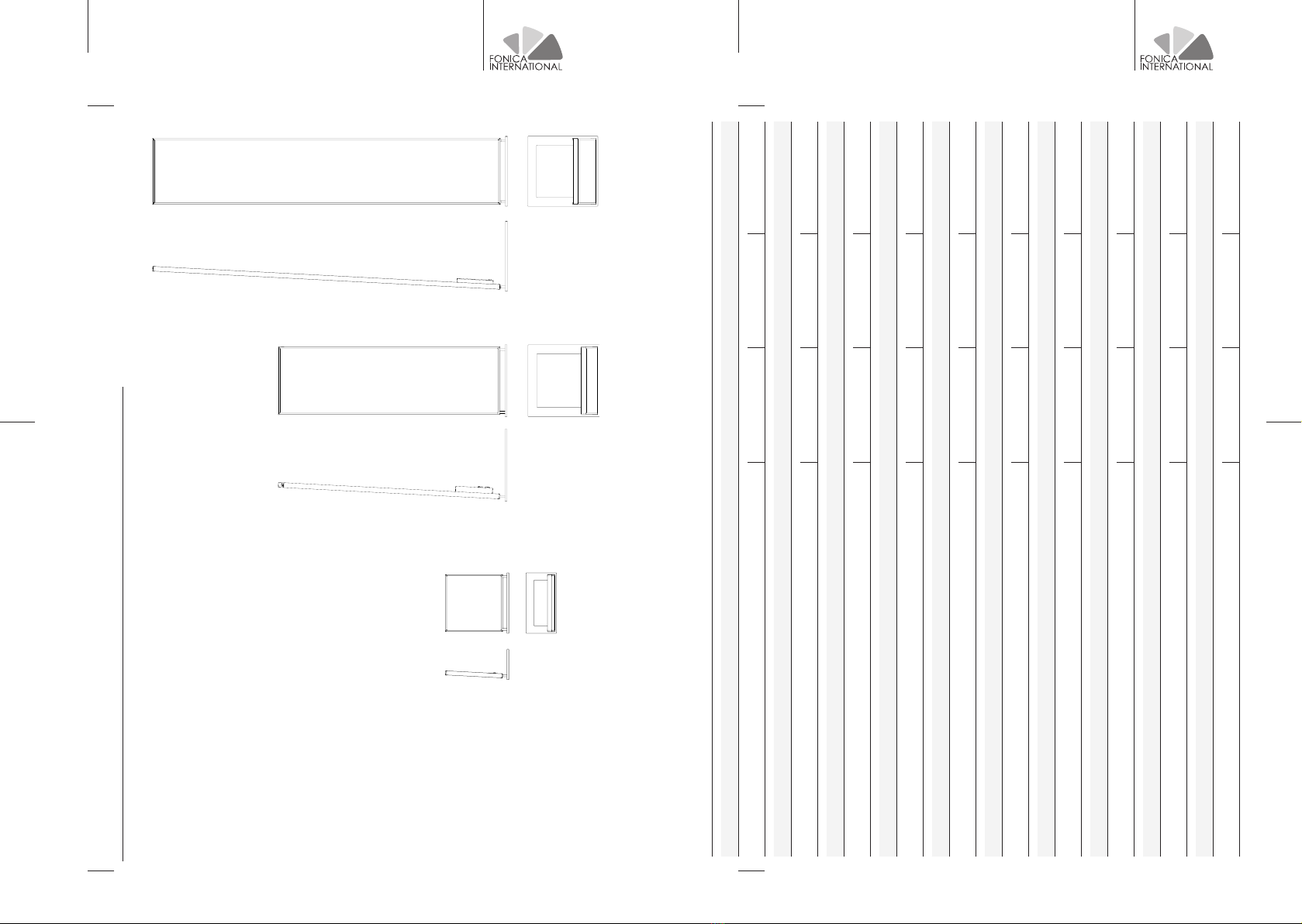
2 / PACKAGING CONTENTS FLAG M/L PASSIVE VERSIONS
FLAG S
PICTURE
N°
CONTENT
A 1
Isodynamic panel
B 1
Base
C 2
M8 screws
D 2
Fixing bars
E 4
Rubber feet
F 2
Jumpers with N.4 banana plugs
G 1
Hex key
A
A
B
B
G
G
C
C
D
D
F
F
E
E
FIGURA N°
CONTENT
A 1
Isodynamic panel
B 1
Base
C 2
M8 screws
D 2
Fixing bars
E 4
Rubber feet
F 2
Banana plugs
G 1
Hex key

www.fonicainternational.com www.fonicainternational.com
FLAG ISODYNAMIC SPEAKERS
98
FLAG ISODYNAMIC SPEAKERS
FLAG M/L ACTIVE VERSIONS
PICTURE
N°
CONTENT
A 1
Isodynamic panel
B 1
Base
C 2
M8 screws
D 2
Fixing bars
E 4
Rubber feet
F 1
Hex key
G 1
Power cord
H 1
Shorting RCA plug
PICTURE
N°
CONTENT
I 1
75 Ohm RCA cable
(1 for a speakers pair)
L 1
Remote control
(1 for a speakers pair)
M 1
Remote control battery
(1 for a speakers pair)
N 1
4 poles connector
with screws*
*Only for analogic input version
3 / ASSEMBLY SEQUENCE
CAUTION!
During the assembly phase, it is important to avoid touching
the part of the speaker covered by the fabric. Below it there is
the speaker membrane which can be damaged by contact with
external bodies. You can safely handle the speaker through its
base and the aluminum: the base, when assembled, becomes
a structural part and can be used to lift or move the
speaker.
CAUTION!
During the assembly process, it’s important to keep away
tools and metal objects from the speaker, as they may be
attracted by the magnetic parts of the speaker, resulting in
potential of damage.
CAUTION!
For the M and L versions it is necessary the assistance of a
second person.
A
B
F
C
D
L
M
H
N
I
G
E

www.fonicainternational.com www.fonicainternational.com
FLAG ISODYNAMIC SPEAKERS
1110
FLAG ISODYNAMIC SPEAKERS
Place the packaging containing the isodynamic panel on a flat, clean and wide enough
surface to be able to hold it up safely (as long as the package, at least twice wider than the
package).
Open the box place the cardboard sheet covering the speaker next to it, so that it can act as a
support surface for the speaker once removed from the package.
STEP 1
STEP 2
CAUTION!
You MUST NOT touch nor get
close with ANY object, especially
ferromagnetic objects that could
be attracted by the powerful
magnets underlying the surface,
to the central area (indicated
by the continuous lines in the
illustration), both from the front
and the back. Instead, handle the
speaker from the peripheral area
(up to 2.5cm from the lateral
edge and from the upper one,
and from about 30cm from the
bottom); be careful not to pull
the profiles.
Pull out the planar speaker, holding it by the
side corners of the profiles, one person for
each short side, without touching the fabric.
STEP 3

www.fonicainternational.com www.fonicainternational.com
FLAG ISODYNAMIC SPEAKERS
1312
FLAG ISODYNAMIC SPEAKERS
Place the planar speaker on the flat surface made with the cardboard sheet inside the
packaging. The planar speaker must be removed from the packaging and placed on the
cardboard surface in the same position. It must not be turned: the connections must remain
on the top. The image represents a passive FLAG M, but the procedure is the same for active
FLAG M with analog input, with digital input and for the relative versions of FLAG L.
Unpack only the bottom part of the speaker,
with two holes at the end. In the illustration,
the planar speaker is completely uncovered
for clarity.
STEP 4 A
STEP 4 B
Insert the bars as deeply as possible into the appropriate holes, on the bottom of the speaker,
keeping the bend point visible on the shaft at 90° in an anti-clockwise direction.
STEP 5
Rotate the bars 90° clockwise to end of stroke.
Also, make sure the bars are anchored to the panel frame by trying to extract them and
pull without turning them. If they have not been inserted correctly, they will slip off. Do not
proceed further until the bars are perfectly hooked, or the final position of the speaker would
be dangerously unstable.

www.fonicainternational.com www.fonicainternational.com
FLAG ISODYNAMIC SPEAKERS
1514
FLAG ISODYNAMIC SPEAKERS
Make sure the bend point should be perfectly on top. Also, make sure the bars are anchored
to the panel frame by trying to extract them and pull without turning them. If they have not
been inserted correctly, they will slip off. Do not proceed further until the bars are perfectly
hooked, or the final position of the speaker would be dangerously unstable.
Remove the base from the packaging and turn it so that the side with the two holes is facing
down. The countersink of the holes needs to be at the opposite side to the bar. Insert the two
supplied M8 screws into the two holes of the base and screw them with the hex key to the
mounted bars on the panel. Make sure the screws are tighten, as they will be responsible of
the entire system stability.
Lift the device by holding it from the base and from the aluminum profiles and
place it on the floor in the right position.
STEP 6
CAUTION!
For absolute safety in using the speakers, use the supplied
double-sided adhesive feet, applying them making them
adhere to the bottom of the base and, after that, to the
previously cleaned floor surface. The adhesive does not
damage the surface of the floor. The surface must be clean,
solid and smooth. Do not apply them on a dirty, uneven,
crumbly or unsuitable surface such as carpets, rugs. The
use of the speaker with other supports can lead to product
instability and cause damages.

www.fonicainternational.com www.fonicainternational.com
FLAG ISODYNAMIC SPEAKERS
1716
FLAG ISODYNAMIC SPEAKERS
4 / POSITIONING IN THE LISTENING ROOM
To better appreciate the sound experience
of the planar FLAG, the speakers should be
placed on the vertices of an ideal equilateral
triangle, where the third vertice is the
listening position. In particular, the right
speaker(recognizable by the serial number
on the back of the speaker, which ends
with the letter R), must be placed on the
right of the listening position, while the left
speaker(recognizable by the serial number
ending with the letter L), must be placed to
the left of the listening position.
FLAG speakers are set with an angle of inclination which allows them to optimise the
listening experience.
The high-frequency membrane of the speakers is a linear sound source, not a punctiform
one. This allows an excellent dispersion on the horizontal plane and therefore, with the
consequence o lateral expansion of the optimal listening point (allowing more people to be
in the ideal listening point). However, this involves a reduced dispersion on the vertical plane,
which is less critical but once identified the ideal listening height just above the centre of the
speakers,(remains the same for all the listeners.
You should also turn the speakers towards
the listening position, as shown in the
figure.
If the listening room permits, it is
recommended to place the speakers at
least 1 meter distance from the walls.
2mt
In case the distance between the two speakers is less than
2 meters, it is recommended to swap the position of the left
and right speakers in order to expand the stereo effect. This
solution is viable by swapping the loudspeakers for passive
or active versions with analogue input; in the case of active
versions with digital input, please contact the seller to edit
the speaker.
Due to the slight changes in the physical properties of the
materials that make up the membranes, the speakers will
reach their maximum potential, in terms of sound quality,
after at least 50 hours of use.
NO
YES
1mt
1mt

www.fonicainternational.com www.fonicainternational.com
FLAG ISODYNAMIC SPEAKERS
1918
FLAG ISODYNAMIC SPEAKERS
You can connect the speaker to an audio amplifier via the supplied banana plugs. Unscrew
the back of the banana plug and insert the stripped wire from the amplifier in the hole as
shown in the illustration, then screw the back part of the connector making sure the cable
is firmly attached to the banana plug. Then insert the banana plugs into the appropriate
sockets on the back of the speaker. In case you are using a cable that already ends up with
banana plugs, you can directly insert it into the sockets, respecting the polarity, without using
the connectors supplied.
ONLY FOR FLAG S
CAUTION!
Respect the colour code
(positive: red / negative: black)
CAUTION!
Respect the colour code
(positive: red / negative: black)
You can connect the speaker to an audio amplifier through MONOWIRING, BIWIRING
or BIAMPLIFICATION connection (see the picture of connection possibilities).
In the first case, a two-pole cable (+ and -) is connected to each speaker from the amplifier
respecting the polarity. In this case, you need to use the jumpers connectors supplied. For
each speaker, insert the jumpers into the appropriate sockets on the speaker respecting
the colour code,(positive:red / negative: black), then connect the cables coming from the
amplifier to two of the four banana connectors on the jumpers. You can insert the stripped
wire by unscrewing the back of the banana plug, then make sure that the cable is well
tightened to the connector (see the picture). It is also possible to insert banana connectors
into the same ones already present on the jumpers, or unscrew the back part of the
connectors to insert spade connectors. It won’t change if you use HIGH or LOW connectors:
connect the + to one of the two + and the - to one of the two -.
In the case of BIWIRING or BIAMPLIFICATION connection, 4 poles must be connected
for each diffuser, two positives and two negatives, in the first case coming from a
single amplifier, instead in the second case they come from two different amplifiers. (In
BIAMPLIFICATION case, to ensure optimal audio reproduction, both amplifiers need to have
the same gain on the signal). In both cases, you can plug the cables directly with the banana
plugs into the sockets on the speakers, following the indication of the polarity (positive /
negative) and of the HIGH and LOW frequencies.
You can also unscrew the supplied banana plugs, remove the jumpers and insert the banana
plugs into the appropriate sockets on the speakers to use them with a stripped cable or
spade connectors.
ONLY FOR PASSIVE FLAG M/L VERSIONS5 / CONNECTION OF THE SPEAKERS
www.fonicainternational.com www.fonicainternational.com
FLAG ISODYNAMIC SPEAKERS
2120
FLAG ISODYNAMIC SPEAKERS
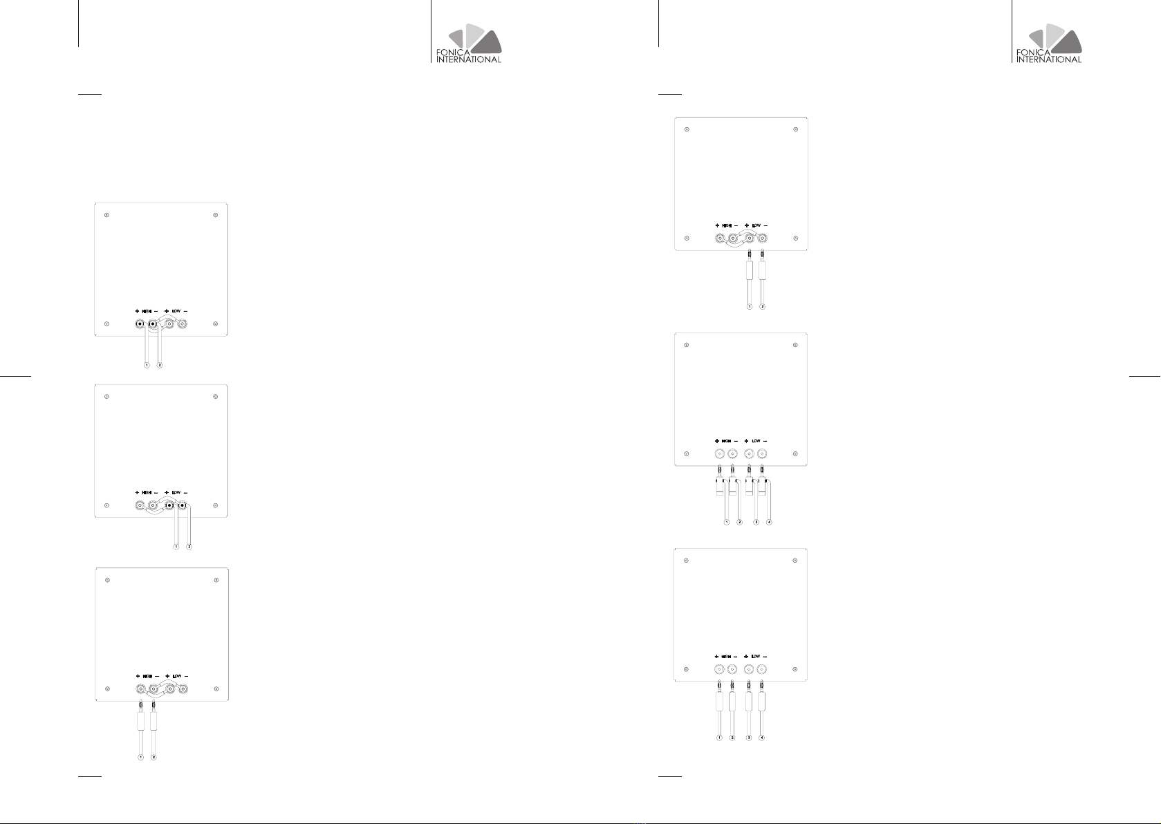
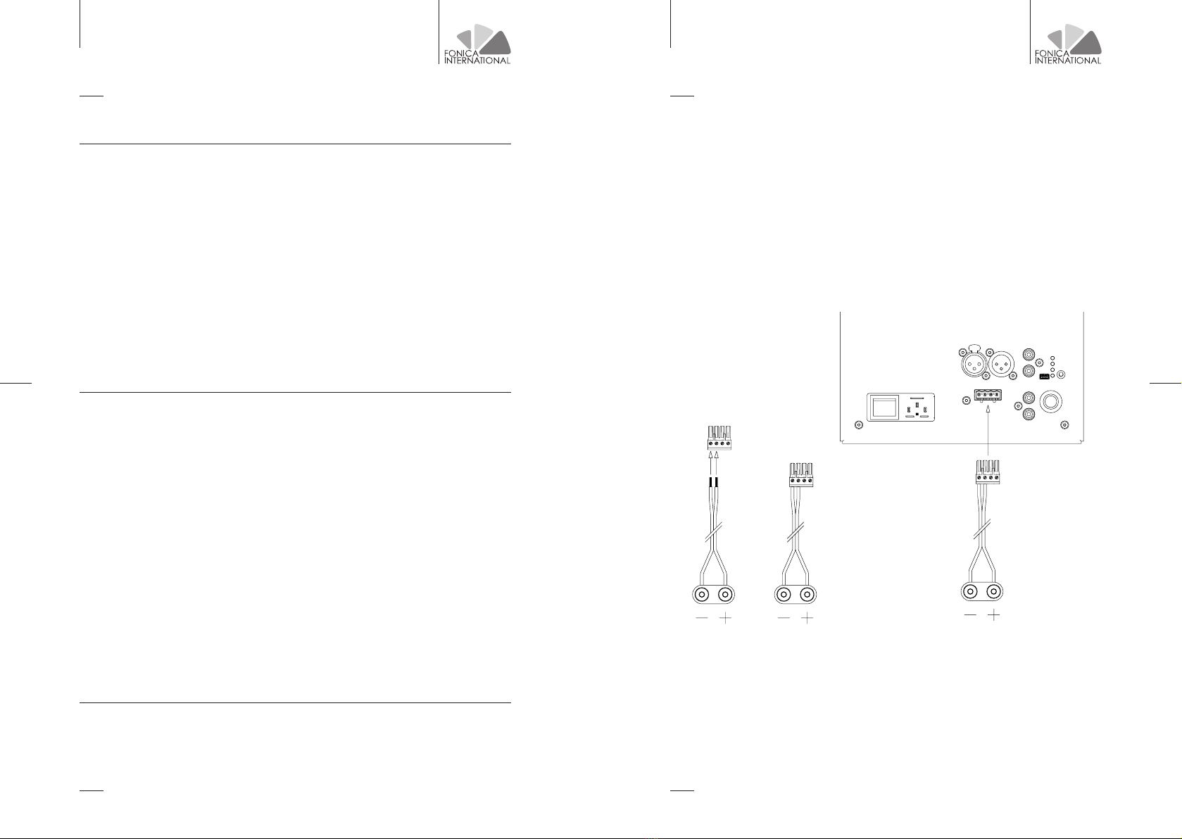
List of connection methods of passive flag M / L versions according to available cables:
single (mono-wiring, with a bipolar cable +/- for each speaker) or double (bi-wiring, with
double bipolar cable +/- for each speaker), with stripped cable or with existing banana plug
terminations. Configurations A and B are equivalent. Configurations C and D are equivalent.
mono-wiring with banana plugs cable,
1 to + of the amplifier, 2 to -
of the amplifier
mono-wiring with stripped cable,
1 to + of the amplifier, 2 to -
of the amplifier
mono-wiring with banana plugs cable,
1 to + of the amplifier, 2 to -
of the amplifier
mono-wiring with stripped cable,
1 to + of the amplifier, 2 to -
of the amplifier
*bi-wiring with stripped cable,
1 to + of the amplifier,
2 to - of the amplifier,
3 to + of the amplifier,
4 to - of the amplifier
*bi-wiring with banana plugs cable,
1 to + of the amplifier,
2 to - of the amplifier,
3 to + of the amplifier,
4 to - of the amplifier
* The bi-wiring solutions are the same for bi-amplification.
A
B
C
D
E
F

www.fonicainternational.com www.fonicainternational.com
FLAG ISODYNAMIC SPEAKERS
2322
FLAG ISODYNAMIC SPEAKERS
HIGH LEVEL INPUT
GAIN
HIGH LEVEL INPUT
- L +
- R +
GAIN
BALANCED IN BALANCED OUT
L
R
CLIP
EQ1
EQ2
EQ3
UNBALANCED
INPUT
EQ
ANALOG
SERVICE
REMOTE IN
REMOTE OUT
POWER SUPPLY
AC INPUT 110 V/ 220 V MAX POWER 650 W
HIGH LEVEL INPUT
GAIN
HIGH LEVEL INPUT
- L +
- R +
GAIN
BALANCED IN BALANCED OUT
L
R
CLIP
EQ1
EQ2
EQ3
UNBALANCED
INPUT
EQ
ANALOG
SERVICE
POWER SUPPLY
AC INPUT 110 V/ 220 V MAX POWER 650 W REMOTE IN
REMOTE OUT
MADE IN ITALYMADE IN ITALY
FLAG M/LFLAG M/L
RIGHT LEFT
234
5
6
7
8
10 9
11
1
SERIAL N. XAX00000LSERIAL N. XAX00000R
1_ IEC 220V power socket with switch
2_ 3 poles XLR balanced analog signal input
3_ 3 poles XLR balanced analog signal output
4_ LEFT unbalanced RCA analog signal input
5_ RIGHT unbalanced RCA analog signal input
6_ USB socket for authorized assistance service connection only
7_ Selector of the three available equalizations and led indicators
8_ TOSLINK digital input
9_ S/PDIF RCA digital input
10_ S/PDIF RCA digital output
11_ AES/EBU XLR 3 poles digital output
12_ AES/EBU XLR 3 poles digital input
ONLY FOR ACTIVE FLAG M/L VERSIONS
DIGITAL INPUT VERSION
Connect the S/PDIF OUT of the left speaker with the supplied 75 ohm RCA cable, to the S/
PDIF IN input of the right speaker (it is possible to recognize the left speaker from the right
one, by reading the last letter of the serial number, located on the back of the speaker).
Here’s an example: (XAX00000L -> Left XAX00000R -> Right)
1_ IEC 220V power socket with switch
2_ 3 poles XLR balanced analog signal input
3_ 3 poles XLR balanced analog signal output
4_ LEFT unbalanced RCA analog signal input
5_ RIGHT unbalanced RCA analog signal input
6_ USB socket for authorized assistance service connection only
7_ Selector of the three available equalizations and led indicators
8_ Knob for gain adjustment
9_ REMOTE IN RCA connector
10_ REMOTE OUT RCA connector
11_ High level analog input 4 poles connector.
ANALOG INPUT VERSION
Connect the REMOTE OUT of the left speaker with the supplied 75 ohm RCA cable, to the
REMOTE IN input of the right speaker (it is possible to recognize the left speaker from the
right one, by reading the last letter of the serial number, located on the back of the speaker).
Here’s an example: (XAX00000L -> Left XAX00000R -> Right)
www.fonicainternational.com www.fonicainternational.com
FLAG ISODYNAMIC SPEAKERS
2524
FLAG ISODYNAMIC SPEAKERS
• Connect the power cords to both speakers by using the switch located on the back of each
speaker, proceed with the ignition of the right speaker and then by turning on the left one.
• Power on (through the switch on the back of the speaker) the RIGHT speaker first and the
LEFT after.
• By pressing the ON / OFF key on the supplied remote control, the green LED of each
speaker will light up intermittently, until the speakers recognize the input signal. The
speakers turn on automatically when they detect an input signal and they turn off after 15
minutes of signal absence.
• In the simple analog version, once both speakers have been turned on with the ON / OFF
buttons on the back, just send them the musical signal, since there is no remote control.
When the speakers go to stand-by due to lack of music signal, they will automatically turn on
again the next time the music signal is sent.
For this version, all the indications of the analog version apply, except for the following
precautions:
• The system is not remote controlled
• The speakers are independent and therefore the modification of the equalization must be
done manually with the selector on the back of the speaker itself.
• The input selection takes place automatically between XLR and RCA, depending on what is
connected and / or used
• You can enter indifferently in the RCA R or L input since the sum of the two inputs is in any
case made.
• Enter with the right channel in the right speaker and with the left channel in the left
speaker.
• Attention, the volume adjustment must be made from the connected preamplifier or in
any case from the connected source, so pay attention to the volume of the source when the
speakers turn on by sending a signal.
• In the simple analog version, once both speakers have been turned on with the ON / OFF
buttons on the back, just send them the musical signal, since there is no remote control.
When the speakers go to stand-by due to lack of music signal, they will automatically turn on
again the next time the music signal is sent.
SERIAL
SERIAL
N. XAX00000
N. XAX00000
L
L
BALANCED IN
BALANCED IN
BALANCED OU
BALANCED OU
T
T
L
L
R
R
CLIP
CLIP
EQ
EQ
1
1
EQ
EQ
2
2
EQ
EQ
3
3
EQ
EQ
ANALO
ANALO
G
G
POWER SUPP
POWER SUPP
LY
LY
AC INPU
AC INPU
T
T
1
1
10 V/ 220 V MAX POWER 650
10 V/ 220 V MAX POWER 650
W
W
SE
SE
RV
RV
IC
IC
E
E
UNBALANCED IN
UNBALANCED IN
MADE IN I
MADE IN I
TA
TA
LY
LY
FLAG M/
FLAG M/
L
L
SIMPLE
SIMPLE
ANALOG
ANALOG
VERSION
VERSION
SIMPLE ANALOG VERSION
www.fonicainternational.com www.fonicainternational.com
FLAG ISODYNAMIC SPEAKERS
2726
FLAG ISODYNAMIC SPEAKERS
• UNBALANCED: connect the RIGHT output of the source to the UNBALANCED RIGHT input
of the right speaker and insert the supplied RCA shorting connector to the UNBALANCED
input LEFT connector on the speaker. Connect the LEFT output of the source to the
UNBALANCED LEFT input of the speaker left and insert the supplied RCA shorting connector
to the UNBALANCED RIGHT input on the speaker.
• BALANCED: connect the RIGHT output of the source to the BALANCED IN input of the right
speaker and the LEFT output of the source to the BALANCED IN input of the left speaker. It is
possible to use the BALANCED OUT of both speakers to transmit the signal to others audio
equipment.
DIGITAL VERSIONS ONLY
ANALOGIC VERSIONS ONLY
• S/PDIF: connect the output of the digital source with a 75 Ohm RCA cable to the S/PDIF
input of the left speaker. The left speaker will pick up the LEFT digital signal, instead
the RIGHT digital signal will be sent to the right speaker through the 75 Ohm RCA cable
previously connected between the two speakers.
• OPTICAL: connect the Toslink optical output of the source with an optical cable to the
OPTICAL IN input of the left speaker. The left speaker will pick up the LEFT digital signal,
while the RIGHT digital signal will be sent to the right speaker through the 75 Ohm RCA cable
previously connected between the two speakers.
• AES/EBU: connect the output source with a 110 Ohm 3 poles XLR cable to the AES/EBU IN
input of the left speaker. The left speaker will pick up the LEFT digital signal, while the RIGHT
digital signal will be sent to the right speaker through the 75 Ohm RCA cable previously
connected between the two speakers. You can use the AES/EBU OUT output to send the
digital signal to other audio equipments with AES/EBU input.
• HIGH LEVEL ANALOGUE: input designed for the connection of external amplifiers. By
using this input, the amplifier inside the speakers does not get excluded. The signal from the
external amplifier is attenuated and then amplified from the internal speaker’s amplifier. It
is necessary to install the appropriate green connector on the power cables coming from the
AUDIO SOURCE CONNECTIONS amplifier following the diagram in the figure, then insert the connector into the appropriate
space on the speaker. You must do it for both speakers.
To connect the provided connector to the cable from the amplifier, unscrew the screws, insert
the stripped cable into the housing under the screw (A), then tighten the screw (B) and finally
insert it into the connector (C).
Make sure to respect the polarity and the position of the cables on the connector and avoid
the wires to come off the connection, as this could cause unwanted contact with potentially
harmful to the connected electronic devices.
• GAIN: the gain knob allows you to adjust the speaker input gain in the case the speaker
remote control is not used, but instead a preamplifier or a source with volume control.
A B C
www.fonicainternational.com www.fonicainternational.com
FLAG ISODYNAMIC SPEAKERS
2928
FLAG ISODYNAMIC SPEAKERS
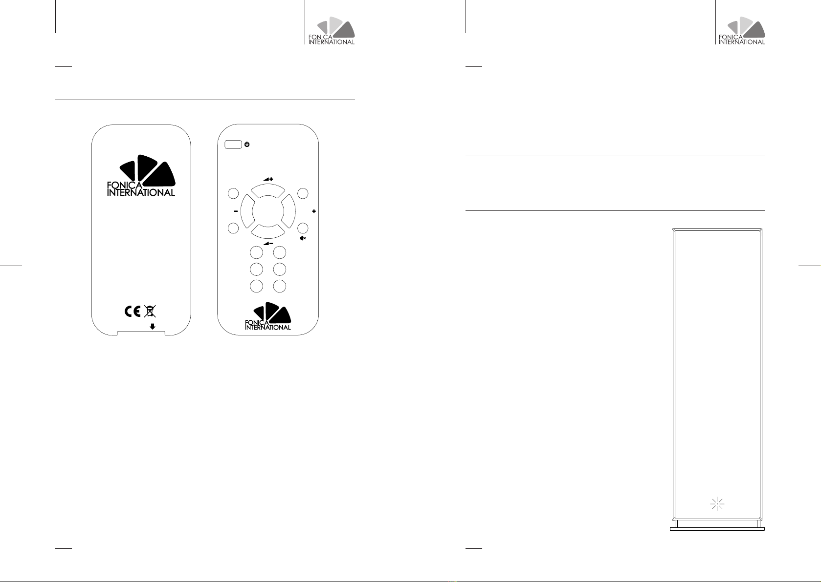
6 / REMOTE CONTROL
• The speakers can be switched on and off by using the ON / OFF apposite button.
• By using the INPUT - and INPUT + key on the remote control, it is possible to sequentially
select the audio inputs.
• By using the VOL + and VOL – keys, it is possible to respectively increase and decrease the
volume level by 1 dB at a time. When switched on, the speakers are automatically set to a
moderate volume level.
• Through the MUTE key it is possible to interrupt the audio output from the speakers. The
green led, on each speaker will start flashing, indicating the mute status. By pressing again
the MUTE key the speaker exits from MUTE state.
• Through the keys EQ1, EQ2, EQ3 it is possible to select 3 different equalization presets
to better adapt the frequency response of the speakers to their position in the listening
environment. CAUTION: each preset stores the audio input used.
• Press the XLR key to select the corresponding input
• Press the RCA key to select the corresponding input
• The AUTO DETECT audio input is selected by default.
With this setting, the speakers detect the presence of signal
on all inputs and it automatically activates the input where
the signal is detected. After 10 seconds of no signal from the
source being used, the speakers will search other signals
from other inputs. If multiple inputs are active at the same
time, the speaker will follow this order of precedence for the
inputs:
1. AES/EBU
2. S/PDIF
3. OPTICAL
4. BALANCED
5. UNBALANCED
• To enter AUTO DETECT mode press the XLR key and then
the INPUT – key.
ONLY ANALOG VERSIONS
• Press the HI-LEVEL key to select the corresponding input
ONLY DIGITAL VERSIONS
• Press the AES/EBU key to select the corresponding input
• Press the S/PDIF key to select the corresponding input
• Press the OPTICAL key to select the corresponding input
INPUT INPUT
EQ1
EQ2 EQ3
XLR
RCA
HI-LEVEL
AES/EBU
S/PDIF
OPTICAL
CR2032
FLAG RC

www.fonicainternational.com www.fonicainternational.com
FLAG ISODYNAMIC SPEAKERS
3130
FLAG ISODYNAMIC SPEAKERS
The active speakers version have a LED in the center, next to the base of the
speaker, as indicated on the illustration. It will light up according to the following:
• Weak STATIC RED light: the speakers are connected to the mains, but they are on
stand-by mode.
• STATIC GREEN light: the speakers are active, and they play the music signal.
• INTERMITTENT GREEN light: the speakers are active but on MUTE mode.
• RED AND GREEN INTERMITTENT: intervention of the soft clip limiter. The speakers
are reaching the maximum output power level. It’s recommended to decrease the
listening volume.
• STATIC RED light: speakers are on fatal error. It is necessary to turn off the speakers
with the appropriate switch, on the back panel. Wait 30 seconds than turn the speakers
on. If the problem persists, contact the assistance.
• INTERMITTENT RED light (1 in a second): temperature is too high, the output power of
the speakers is limited until the temperature is within the normal range of use.
• INTERMITTENT RED light (2 in a second): temperature is too low for the correct
speaker operation.
• When a key on the remote control is pressed, the green LED on the left speaker flashes
to indicate that the command has been received.
To control the speakers with the remote control, point it at the left speaker LED.
7 / LED INDICATORS ON THE BACK PANEL
• INTERMITTENT RED light during the peak of music signal: intervention of the soft clip
limiter. The speakers are reaching the maximum output power level. It is recommended
decreasing the listening volume.
• STATIC RED light: fatal error. It is necessary to turn off the speakers with the
appropriate switch, located on the back of the panel. Wait 30 seconds, then turn
on the speakers. If the problem persists, contact the assistance.
• INTERMITTENT RED light (1 in a second): temperature is too high, the output
power of the speakers is limited until the temperature is within the normal
range of use.
• INTERMITTENT RED light (2 in a second): temperature is too low for the correct
speaker operation.
• STATIC GREEN light: the speakers are active and playing the music signal.
• INTERMITTENT GREEN light: the speakers are active, but on MUTE mode.
• Green led EQ1 indicates that equalization curve number 1 is selected.
• Green led EQ2 indicates that equalization curve number 2 is selected.
• Green led EQ3 indicates that equalization curve number 3 is selected.
www.fonicainternational.com www.fonicainternational.com
FLAG ISODYNAMIC SPEAKERS
3332
FLAG ISODYNAMIC SPEAKERS
11 / TECHNICAL SPECIFICATIONS
DIMENSIONS (mm) panel only (LxHxP) S M L
380x380x30 380x1240x30 380x1990x30
DIMENSIONS (mm) panel with back electronic parts (LxHxP)
380x380x32 380x1240x65 380x1990x65
DIMENSIONS (mm) total including the base (LxHxP)
400x422x200 400x1282x400 400x2031x400
WEIGHT (Kg) of the panel only
4,6 16,3 27,4
WEIGHT (Kg) of the panel with base
9,6 22,9 34
DIMENSIONS (mm) of the base (LxHxP)
400x12x200 400x12x400 400x12x400
WEIGHT (Kg) of the base
5 6,6 6,6
EFFICIENCY (dB/W/m) passive versions
85 86 87
NOMINAL IMPEDANCE (Ω) passive versions
648
FREQUENCY RESPONSE (Hz)
80-20K 60-20K 50-20K
www.fonicainternational.com
FLAG ISODYNAMIC SPEAKERS
34
9 / WARRANTY ACTIVATION
10 / ASSISTANCE
8 / CLEANING AND MAINTENANCE
• To clean the fabric parts of the speaker, gently stroke with asoft brush, making
sure not to press too firmly.
• To clean the aluminum parts of the speaker, use a damp soft cloth.
To activate the warranty please email direzione@fonica-international.com with the serial
number of the speakers and the purchase documents, specifying the date of the purchase.
For technical assistance email direzione@fonica-international.com
Customers residing in Italy can directly contact us by calling +39 035.42.18.936
CAUTION!
Before cleaning the speaker, you must turn it off by pushing
the switch on the rear and remove the power cord from the
mains.
www.fonicainternational.com

www.fonicainternational.com
FONICA INTERNATIONAL S.R.O. – Via Costanza Cerioli, 65 - 24068 · Seriate (BG) - Italy
P.IVA CZ64508587 - info@fonicainternational.com
Table of contents


