Fonrich FR-DCMG-MMPY User manual

1
User Manual
Version 4.2
DC System Monitor:FR-DCMG-MMPY
丰郅(上海)新能源科技有限公司
Fonrich (Shanghai) New Energy Technology Co., Ltd.
Add: 1st Floor, Building 5, No.999 Jiangyue Road, Minhang District,Shanghai
Web: www.fonrich.com
Tel: +86 21 61679671
Email: [email protected]

2
Table of Contents
Product description.......................................................................................................................................... 3
The main function..................................................................................................................................... 3
Documentation statement......................................................................................................................3
Terminal definition....................................................................................................................................4
Controller connection diagram............................................................................................................. 5
Ground connection and communication shield............................................................................... 6
Operation interface display............................................................................................................................ 7
Key operation............................................................................................................................................. 7
Initial interface display............................................................................................................................. 7
Histogram interface.......................................................................................................................... 7
Channel current and power generation display interface..................................................... 9
Parameter setting interface..................................................................................................................10
Current calibration setting interface..........................................................................................10
Software version number display interface............................................................................. 10
Alarm status display interface............................................................................................................. 11
Channel arc fault alarm interface................................................................................................11
Fault alarm clear interface............................................................................................................ 11
Items that can generate alarms can be set..............................................................................12
Alarm conditions..................................................................................................................................... 12
Alarm message................................................................................................................................ 13
MODBUS Protocol definition.......................................................................................................................14
Communication format configuration...................................................................................... 14
Data frame format description (refer to Modbus RTU standard)......................................14
Function code description............................................................................................................ 14
Register description........................................................................................................................15
Register description in bit units (function code 02)
......................................................... 15
Register description in word unit (function code 03 04 06)
..........................................28
Appendix........................................................................................................................................................... 34
FAQ..............................................................................................................................................................34
Document revision record.................................................................................................................... 35
Contact us................................................................................................................................................. 37

3
Product description
FR-DCMG DC monitor products are mainly used in DC power transmission and distribution,
such as photovoltaic combiner boxes, DC cabinets, telecommunications equipment rooms
and communication base stations. It communicates with the host computer through RS485
or industrial wireless. Its main function is to monitor the current of each branch in the DC
system, the bus voltage, the temperature of the cabinet, the status of the lightning arrester
and the status of the DC breaker. It can realize automatic alarm for abnormal conditions and
real-time detection of the presence of harmful arcs in the DC circuit.
The main function
•
Monitoring function: Real-time monitoring of the generation current, voltage,
temperature of the combiner box, lightning arrester status, DC circuit breaker status,
and DC arc fault status of each photovoltaic string in the combiner box, and
communicate with the host computer through RS485.
•
Display content: For the detected voltage, current, temperature, switching state,
power generation and other data, the FR-DCMG-MMPY can display a histogram
interface through the LCD to read the current and other data more intuitively.
•
Alarm function: It can be configured to open or close the alarm according to the
actual needs of the scene. When the alarm occurs, the interface will pop up an alarm
message.
•
Current calibration: identify zero drift and improve the accuracy of current
identification. (Default off)
•
Compatibility:Program compatible model FR-DCMG-MMPD products
Documentation statement
This manual is applicable to the monitoring host whose model is FR-DCMG-MMPY.
The software version is A0F2.
See page 11 for software version viewing method
4
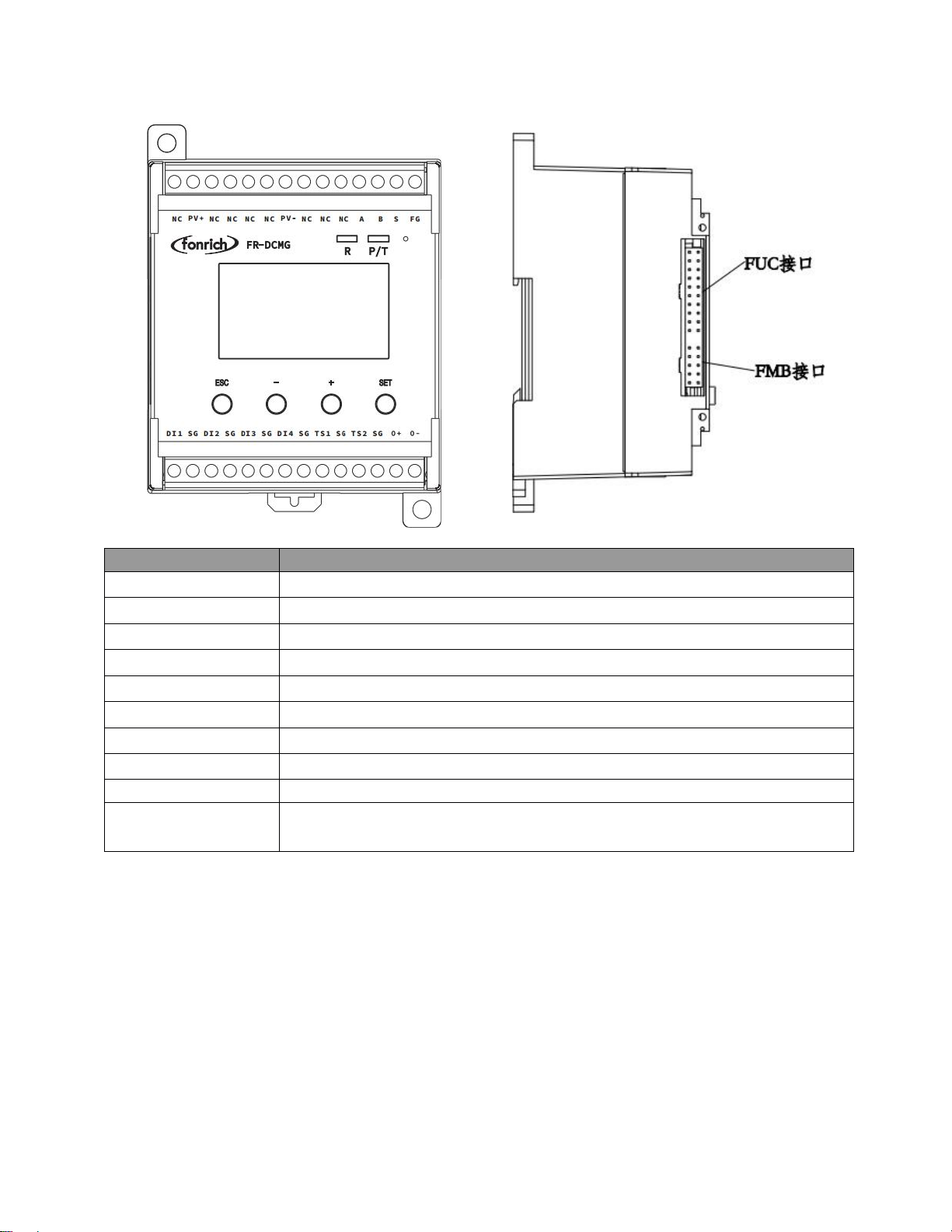
Terminal definition
Symbol
Meaning
PV+ . PV-
PV DC bus power supply terminal
NC
Not connecion
S
Not connecion
A.B
RS485 Communication terminal
FG
Fixed Ground terminal
TS1.TS2
Externally connected temperature sensor terminals
SG
Temperature sensor and digital input ground terminal
DI1.DI2.DI3.DI4
4 digital input terminals
FUC
Can connect modules with FUC interface
FMB
Modules with an FMB interface can be connected, such as the FR-DCMG-AS4A
DC Arc Detector.

5
Controller connection diagram

6
Ground connection and communication shield
The FG terminal of the FR-DCMG must be grounded, otherwise communication will
interfere and the reliability of the device will decrease. The grounding wire should be
grounded nearby. The grounding wire should be no more than 15cm from the “FG”
terminal to the bottom of the combiner box. It is recommended to be within 10cm. The
shorter the better, the thicker the better. The bottom of the combiner box should be
connected to the ground. The main control unit module is fixed on a standard guide rail
with a width of 3.5 cm.
The wiring specifications of the communication shielded wire are shown in the figure above:
The wiring of on-site communication lines requires that the communication shield can only
be grounded at a single point, otherwise there will be a risk of lightning surge damage to
all equipment on the entire communication line during a lightning strike;
If you encounter a situation where communication line interference is too large to
communicate, you can refer to the figure above, and insert a high voltage capacitor C
<100nF between the shielded wire of each combiner box and the ground wire, and use
this capacitor to filter the shielding layer interference.

7
Operation interface display
Key operation
FR-DCMG-MMPY has four keys “ESC”, “-”, “+”, and “SET”.
"ESC" key is used to return to the default interface and cancel parameter setting;
“SET”key is used to enter the parameter setting mode, select the parameter to be set and
complete the setting of the parameter;
The "+" and "-" keys are used to scroll the screen and adjust parameters;
Press the "+" and "-" keys at the same time to display the software version interface;
Press the "ESC" and "-" keys simultaneously to display the current calibration interface;
If there is no key operation for 10 seconds, the interface will automatically jump to the
default interface of the current mode, and the brightness will decrease after 5 seconds.
Initial interface display
The factory default is Modbus mode. When the host computer is connected to the
device via RS485 and communicates, the LED lights “R” and “P / T” will flash
alternately to indicate normal communication. When the device is not connected to
communication, it restarts by default every 5 minutes, or you can turn off the default
restart function, which can be turned off through the 0xF003 register.
Histogram interface
The histogram interface is the default display interface of Modbus mode, as shown
below:
The histogram in the figure shows the current value detected by each channel. The
initial interface display range is: -2A ~ 10A. You can also set register 0x0B16, which
displays -2A ~ 20A and -2A ~ 30A. Because a six-channel Hall sensor is connected, every

8
six channels are distinguished during display, and the current channels are from 1 to 24 in
order from left to right. The order of the current channels can also be set in reverse order.
The lightning icon in the upper left corner indicates that the FR-DCMG-MMPY horn-
connected Hall sensor with arc monitoring function; "24" indicates the current online arc
and current channel number; "1111" indicates the real-time status of the digital input DI1
~ DI4; "1250V" Represents the real-time voltage value of the bus. If there is no key
operation within 5 seconds, the screen brightness will decrease.
9
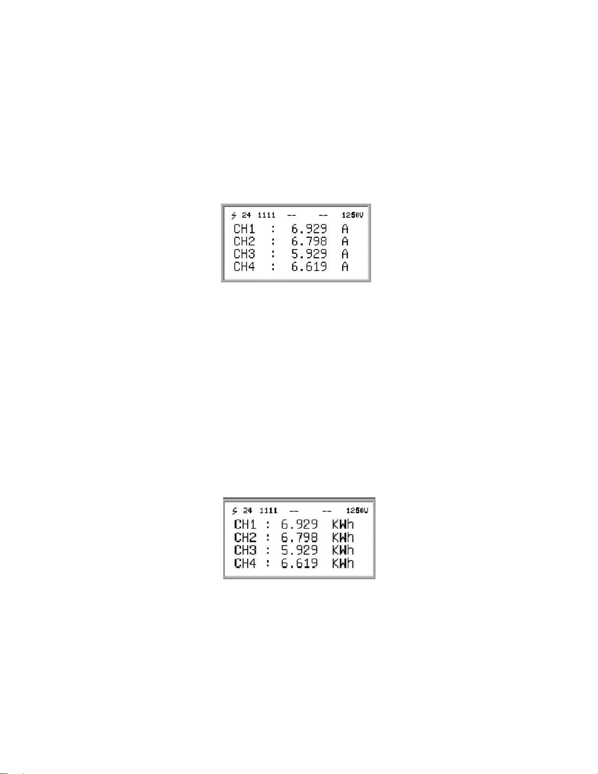
Channel current and power generation display interface
In the histogram mode, press the "+" or "-" key to enter the channel current and
power generation display interface. The current value and cumulative power generation of
each channel are displayed on the screen. When the "+" key is pressed first, the digital
value of the current is displayed first, and when the "-" is pressed first, the digital value of
the current is displayed first
The value of cumulative power generation. When viewing the values of current and
cumulative power generation, you can scroll through the screen by continuing to press the
"+" or "-" key. After the current display is completed, continue to press the "+" key to start
displaying the cumulative power generation. The figure above shows the current display
interface. “CH1:” in the figure indicates that the current value monitored by channel 1 in
real time is “6.929A”, and so on.
The figure below shows the cumulative power generation display interface. "CH1:" in
the figure indicates that the cumulative power generation of channel 1 is "6.929kwh", and
so on.
10
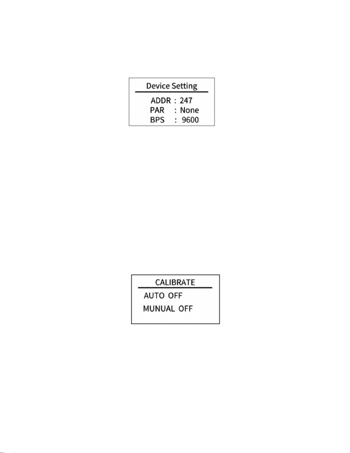
Parameter setting interface
In the histogram interface, press the "SET" key to enter the Modbus parameter
setting interface. The Modbus parameter setting is as follows:
•
ADDR: The communication address of the Modbus slave node, the range is 1 ~ 247 (default is
247).
•
PAR: The data verification method of Modbus communication. The optional parity (None), odd
parity (Odd), even parity (Even), and no parity by default.
•
BPS: Baud rate for Modbus communication. The selectable baud rates are 2400, 4800, 9600
(default), 19200, 38400.
Current calibration setting interface
Press the "ESC" and "-" keys at the same time to enter the current calibration setting
interface, as shown below:
To use this feature, please contact the company's technical support staff.
Software version number display interface
In the histogram interface, press the "+" and "-" keys at the same time to enter the
software version number display interface, as shown below:

11
•
HV:Keep
•
SV:Software version number
•
ST:Keep
Alarm status display interface
Alarm messages can be cleared remotely and manually. Manual clearing requires
long-pressing the host's "ESC" key for 2 seconds, remote clearing requires writing "1" to
register 0x0079 to clear. If an arc alarm occurs, it must be cleared manually or remotely.
Restarting the host will still display the alarm message.
Channel arc fault alarm interface
After the DC arc sensor detects the occurrence of a fault arc, the alarm information
interface of the host is as shown below.
In the figure above: "02" means channel arc fault alarm, and "4" means that the fault
arc alarm channel is 4.
Fault alarm clear interface
The host sends an alarm when it detects a fault, and the user can choose to handle it
locally or remotely. By long-pressing the "ESC" key for about 2 seconds locally, the

12
system jumps out of the interface as shown below, indicating that the alarm status has
been cleared; remote processing needs to write "1" to 0x0079 to clear, and the interface
shown below will be displayed after clearing successfully.
Items that can generate alarms can be set
Voltage is too high
Voltage is too low
Temperature is too high
Channel reverse current
Total reverse current is too high
Total current is too high
Total current is too low
Channel without current
Low channel current
High channel current
Channel current value undercurrent
Channel current value overcurrent
Lightning Arrester Status (DI1)
circuit breaker status (DI2)
Switch DI3 status
Switch DI4 status
Alarm conditions

13
1.
Current reverse, no current, under current, over current, low current, high current, etc.
a. Only when the average value of the channel current is greater than the
set alarm threshold of the current channel, the alarm function of the above
current-related items is activated; otherwise, the alarm status is forcibly
cleared to 0.
b. As for whether the alarm needs to be separately met the respective alarm
conditions (above or below the respective alarm threshold).Alarm message
c. Check if the corresponding alarm register is open, closed by default
Alarm message
•
Undercurrent alarm. After the channel average current value is subtracted from the
overcurrent / undercurrent alarm threshold, the current value is still less than or
equal to the current channel start alarm start threshold. The overcurrent /
undercurrent alarm threshold will change as the average current changes.Alarm
message
•
Over current alarm. After the channel average current value plus the over current /
under current alarm threshold, the current value is still greater than or equal to the
current channel start alarm start threshold. The over current / under current alarm
threshold will change as the average current changes.Alarm message
•
Low current alarm, when the current is less than or equal to the channel current low
alarm threshold, an alarm occurs.Alarm message
•
High current alarm. When the current is greater than or equal to the channel current
high alarm threshold, an alarm occurs.Alarm message
•
No current alarm, when the absolute value of the current is less than 250mA, an alarm
occurs.Alarm message

14
MODBUS Protocol definition
Communication format configuration
•
Modbus communication mode: RTU mode
•
Address of the slave device: range form 1 to 247 (default 247)
•
Baud rate (bps): 2400, 4800, 9600 (default), 19200, 38400
•
Byte check mode: odd check, even check, no check (default)
Data frame format description (refer to Modbus RTU standard)
The byte in the communication frame composed by 1 start bit, 8 bits data bit, 1 parity
bit, 1 stop bit like the below table(Refer to standard modbus RTU protocol):
Table 1: Data frame format table
Address Code
Function Code
Data Area
Check Zone
1byte
1byte
N*1byte
2bytes
The address code is used to identify the slave that receives the data frame and the
response frame sent by that slave. The function code indicates how the master requires
the slave to respond and the slave responds to that function code. Data area The content
can be the address value, the number of registers, the data from the slave response and
the data sent by the master to the slave, etc., which can hold up to 252 bytes of data. The
check area uses CRC cyclic redundancy to check whether a frame of data is wrong. The
high byte of the data frame comes first, and the low byte comes after.
Function code description
Register reads and writes in bits
•
Function code 01 used to read the contents of the bit register
•
Function code 02 used to reads the contents of the bit register
•
Function code 05 used to write single bit-type registers

15
The contents represented by the register in bits are: switch value, alarm information,
etc.
Register read and write in word units
•
Function codes 03、04 are used to read multiple word-type registers
•
Function code 06 is used to write single word-type registers
•
Function code 16 is used to multiple word-type registers
The content of the word-type registers can be voltage, current, generated energy, etc
Register description
Register description in bit units (function code 02)
Bit address
Functional description
remark
Hex
Decimal
0x021E
542
-
-
0x0230
560
-
-
0x0231
561
Channel arc alarm status
This bit is set when the channel arc strength is above the alarm
threshold. Clear the alarm and set it to 0.
0x0232
562
Bus voltage too low alarm
status
This bit is set when the bus voltage is below the alarm
threshold. Cleared below the alarm release threshold
0x0233
563
Bus voltage to high alarm
status
This bit is set when the bus voltage exceeds the alarm
threshold. Cleared below the alarm release threshold
0x0234
564
Temperature sensor 1
high temperature alarm
status
This bit is set when the temperature sensor 1 temperature
exceeds the alarm threshold. Cleared below the alarm release
threshold
0x0235
565
Temperature sensor 2
high temperature alarm
status
This bit is set when the temperature sensor 2 temperature
exceeds the alarm threshold. Cleared below the alarm release
threshold
0x0236
566
Channel reverse current
When the reverse current is generated in the channel, the

16
alarm status
position is 1, and the alarm is cleared.
0x0237
567
Total reverse current
alarm status
This bit is set when the total reverse current exceeds the alarm
threshold. Cleared below the alarm release threshold
0x0238
568
Total current too low
alarm state
This bit is set when the total current exceeds the alarm
threshold. Cleared below the alarm release threshold
0x0239
569
Total current too high
alarm state
This bit is set when the total current exceeds the alarm
threshold. Cleared below the alarm release threshold
0x023A
570
Channel current value
zero
The channel has no current alarm and this bit is set to 1.
0x023B
571
Channel current value
undercurrent
Channel undercurrent alarm, this bit is set to 1
0x023C
572
Channel current value
overcurrent
Channel overcurrent alarm, this bit is set to 1.
0x023D
573
Channel current value is
too low
Channel current low alarm, this bit is set to 1
0x023E
574
Channel current value is
too high
Channel current high alarm, this bit is set to 1
0x0240
576
Switch 1 alarm status
The state of the device's input switch DI1, 0: open, 1: closed
0x0241
577
Switch 2 alarm status
The state of the device's input switch DI2, 0: open, 1: closed
0x0242
578
Switch 3 alarm status
The state of the device's input switch DI3, 0: open, 1: closed
0x0243
579
Switch 4 alarm status
The state of the device's input switch DI4, 0: open, 1: closed
.......
..........
....................
..........................
0x0260
608
Channel 1 arc alarm status
When the arc intensity of the channel is greater than the alarm
threshold, this bit is set to 1; after clearing the alarm, it is set to
0
0x0261
609
Channel 2 arc alarm status
When the arc intensity of the channel is greater than the alarm
threshold, this bit is set to 1; after clearing the alarm, it is set to
0
0x0262
610
Channel 3 arc alarm status
When the arc intensity of the channel is greater than the alarm
threshold, this bit is set to 1; after clearing the alarm, it is set to
0
0x0263
611
Channel 4 arc alarm status
When the arc intensity of the channel is greater than the alarm
threshold, this bit is set to 1; after clearing the alarm, it is set to

17
0
0x0264
612
Channel 5 arc alarm status
When the arc intensity of the channel is greater than the alarm
threshold, this bit is set to 1; after clearing the alarm, it is set to
0
0x0265
613
Channel 6 arc alarm status
When the arc intensity of the channel is greater than the alarm
threshold, this bit is set to 1; after clearing the alarm, it is set to
0
0x0266
614
Channel 7 arc alarm status
When the arc intensity of the channel is greater than the alarm
threshold, this bit is set to 1; after clearing the alarm, it is set to
0
0x0267
615
Channel 8 arc alarm status
When the arc intensity of the channel is greater than the alarm
threshold, this bit is set to 1; after clearing the alarm, it is set to
0
0x0268
616
Channel 9 arc alarm status
When the arc intensity of the channel is greater than the alarm
threshold, this bit is set to 1; after clearing the alarm, it is set to
0
0x0269
617
Channel 10 arc alarm
status
When the arc intensity of the channel is greater than the alarm
threshold, this bit is set to 1; after clearing the alarm, it is set to
0
0x026A
618
Channel 11 arc alarm
status
When the arc intensity of the channel is greater than the alarm
threshold, this bit is set to 1; after clearing the alarm, it is set to
0
0x026B
619
Channel 12 arc alarm
status
When the arc intensity of the channel is greater than the alarm
threshold, this bit is set to 1; after clearing the alarm, it is set to
0
0x026C
620
Channel 13 arc alarm
status
When the arc intensity of the channel is greater than the alarm
threshold, this bit is set to 1; after clearing the alarm, it is set to
0
0x026D
621
Channel 14 arc alarm
status
When the arc intensity of the channel is greater than the alarm
threshold, this bit is set to 1; after clearing the alarm, it is set to
0
0x026E
622
Channel 15 arc alarm
status
When the arc intensity of the channel is greater than the alarm
threshold, this bit is set to 1; after clearing the alarm, it is set to
0
0x026F
623
Channel 16 arc alarm
status
When the arc intensity of the channel is greater than the alarm
threshold, this bit is set to 1; after clearing the alarm, it is set to
0

18
0x0270
624
Channel 17 arc alarm
status
When the arc intensity of the channel is greater than the alarm
threshold, this bit is set to 1; after clearing the alarm, it is set to
0
0x0271
625
Channel 18 arc alarm
status
When the arc intensity of the channel is greater than the alarm
threshold, this bit is set to 1; after clearing the alarm, it is set to
0
0x0272
626
Channel 19 arc alarm
status
When the arc intensity of the channel is greater than the alarm
threshold, this bit is set to 1; after clearing the alarm, it is set to
0
0x0273
627
Channel 20 arc alarm
status
When the arc intensity of the channel is greater than the alarm
threshold, this bit is set to 1; after clearing the alarm, it is set to
0
0x0274
628
Channel 21 arc alarm
status
When the arc intensity of the channel is greater than the alarm
threshold, this bit is set to 1; after clearing the alarm, it is set to
0
0x0275
629
Channel 22 arc alarm
status
When the arc intensity of the channel is greater than the alarm
threshold, this bit is set to 1; after clearing the alarm, it is set to
0
0x0276
630
Channel 23 arc alarm
status
When the arc intensity of the channel is greater than the alarm
threshold, this bit is set to 1; after clearing the alarm, it is set to
0
0x0277
631
Channel 24 arc alarm
status
When the arc intensity of the channel is greater than the alarm
threshold, this bit is set to 1; after clearing the alarm, it is set to
0
.......
........
.................
.......................
0x027F
639
Channel 32 arc alarm
status
When the arc intensity of the channel is greater than the alarm
threshold, this bit is set to 1; after clearing the alarm, it is set to
0
0x0280
640
Channel 1 current reverse
alarm status
This bit is set when the channel current is reversed and greater
than the alarm threshold, otherwise cleared.
0x0281
641
Channel 2 current reverse
alarm status
This bit is set when the channel current is reversed and greater
than the alarm threshold, otherwise cleared.
0x0282
642
Channel 3 current reverse
alarm status
This bit is set when the channel current is reversed and greater
than the alarm threshold, otherwise cleared.
0x0283
643
Channel 4 current reverse
alarm status
This bit is set when the channel current is reversed and greater
than the alarm threshold, otherwise cleared.

19
0x0284
644
Channel 5 current reverse
alarm status
This bit is set when the channel current is reversed and greater
than the alarm threshold, otherwise cleared.
0x0285
645
Channel 6 current reverse
alarm status
This bit is set when the channel current is reversed and greater
than the alarm threshold, otherwise cleared.
0x0286
646
Channel 7 current reverse
alarm status
This bit is set when the channel current is reversed and greater
than the alarm threshold, otherwise cleared.
0x0287
647
Channel 8 current reverse
alarm status
This bit is set when the channel current is reversed and greater
than the alarm threshold, otherwise cleared.
0x0288
648
Channel 9 current reverse
alarm status
This bit is set when the channel current is reversed and greater
than the alarm threshold, otherwise cleared.
0x0289
649
Channel 10 current
reverse alarm status
This bit is set when the channel current is reversed and greater
than the alarm threshold, otherwise cleared.
0x028A
650
Channel 11 current
reverse alarm status
This bit is set when the channel current is reversed and greater
than the alarm threshold, otherwise cleared.
0x028B
651
Channel 12 current
reverse alarm status
This bit is set when the channel current is reversed and greater
than the alarm threshold, otherwise cleared.
0x028C
652
Channel 13 current
reverse alarm status
This bit is set when the channel current is reversed and greater
than the alarm threshold, otherwise cleared.
0x028D
653
Channel 14 current
reverse alarm status
This bit is set when the channel current is reversed and greater
than the alarm threshold, otherwise cleared.
0x028E
654
Channel 15 current
reverse alarm status
This bit is set when the channel current is reversed and greater
than the alarm threshold, otherwise cleared.
0x028F
655
Channel 16 current
reverse alarm status
This bit is set when the channel current is reversed and greater
than the alarm threshold, otherwise cleared.
0x0290
656
Channel 17 current
reverse alarm status
This bit is set when the channel current is reversed and greater
than the alarm threshold, otherwise cleared.
0x0291
657
Channel 18 current
reverse alarm status
This bit is set when the channel current is reversed and greater
than the alarm threshold, otherwise cleared.
0x0292
658
Channel 19 current
reverse alarm status
This bit is set when the channel current is reversed and greater
than the alarm threshold, otherwise cleared.
0x0293
659
Channel 20 current
reverse alarm status
This bit is set when the channel current is reversed and greater
than the alarm threshold, otherwise cleared.
0x0294
660
Channel 21 current
reverse alarm status
This bit is set when the channel current is reversed and greater
than the alarm threshold, otherwise cleared.

20
0x0295
661
Channel 22 current
reverse alarm status
This bit is set when the channel current is reversed and greater
than the alarm threshold, otherwise cleared.
0x0296
662
Channel 23 current
reverse alarm status
This bit is set when the channel current is reversed and greater
than the alarm threshold, otherwise cleared.
0x0297
663
Channel 24 current
reverse alarm status
This bit is set when the channel current is reversed and greater
than the alarm threshold, otherwise cleared.
.....
.......
.................
....................
0x029F
671
Channel 32 current
reverse alarm status
This bit is set when the channel current is reversed and greater
than the alarm threshold, otherwise cleared.
0x02A0
672
Channel 1 no current
alarm status
This bit is set to 1 when there is no current in this channel,
otherwise cleared.
0x02A1
673
Channel 2 no current
alarm status
This bit is set to 1 when there is no current in this channel,
otherwise cleared.
0x02A2
674
Channel 3 no current
alarm status
This bit is set to 1 when there is no current in this channel,
otherwise cleared.
0x02A3
675
Channel 4 no current
alarm status
This bit is set to 1 when there is no current in this channel,
otherwise cleared.
0x02A4
676
Channel 5 no current
alarm status
This bit is set to 1 when there is no current in this channel,
otherwise cleared.
0x02A5
677
Channel 6 no current
alarm status
This bit is set to 1 when there is no current in this channel,
otherwise cleared.
0x02A6
678
Channel 7 no current
alarm status
This bit is set to 1 when there is no current in this channel,
otherwise cleared.
0x02A7
679
Channel 8 no current
alarm status
This bit is set to 1 when there is no current in this channel,
otherwise cleared.
0x02A8
680
Channel 9 no current
alarm status
This bit is set to 1 when there is no current in this channel,
otherwise cleared.
0x02A9
681
Channel 10 no current
alarm status
This bit is set to 1 when there is no current in this channel,
otherwise cleared.
0x02AA
682
Channel 11 no current
alarm status
This bit is set to 1 when there is no current in this channel,
otherwise cleared.
0x02AB
683
Channel 12 no current
alarm status
This bit is set to 1 when there is no current in this channel,
otherwise cleared.
0x02AC
684
Channel 13 no current
alarm status
This bit is set to 1 when there is no current in this channel,
otherwise cleared.
Table of contents
Other Fonrich Measuring Instrument manuals


Popular Measuring Instrument manuals by other brands


RS PRO
RS PRO RS-91 instruction manual

Tymate
Tymate M12-3 user manual

Watts
Watts HF scientific 28052 Owner's and user's manual

THORLABS
THORLABS PM200 Operation manual

Sherwood Scientific
Sherwood Scientific 410 Industrial Operator's manual

Keysight Technologies
Keysight Technologies N9320A RF Configuration guide

iSystem
iSystem iC5000 Hardware reference

Sierra
Sierra InnovaMass 240i Series instruction manual

Streetwize
Streetwize leisurewize TPMS1 manual

MAHA
MAHA SKM 2 Original operating instructions

Hanna Instruments
Hanna Instruments HI 98713 instruction manual

Analytical Technology
Analytical Technology Q46H/79PR manual