Fonrich FR-DCMG Series User manual

FR-DCMG DC System Monitor User Manual Fonrich New Energy Technology Co., td.
FR-DCMG DC System Monitor
User Manual (V2.0)
Fonrich (Shanghai) New Energy Technology Co.,Ltd
Address: 1st Floor, B ilding 5, No.999 Jiangy e Road, Minhang District,Shanghai
Zip Code: 201112
Web: www.fonrich.com
Email: s [email protected], [email protected]
Service Hotline: +86-21-60717303
1

Table of contents
Table of contents
Ⅰ, Important Safety Instr ctions.........................................................................................................3
Ⅱ,Prod ct Brief................................................................................................................................4
Ⅲ Mechanical Dimensions & Str ct re..............................................................................................5
FR-DCMG-MMPA /FR-DCMG-MMPB /FR-DCMG-MMPT Main Unit......................................5
FR-DCMG-HS4A /FR-DCMG-AS4A Hall C rrent Sensor............................................................6
FR-DCMG-HS4T /FR-DCMG-AS4T Hall C rrent Sensor............................................................6
FR-PVMA-LHSA Leakage C rrent Sensor....................................................................................7
FR-PVMG-SHTPA /FR-PVMG-SHTPT Sh nt Trip Power Unit...................................................7
Ⅳ, Connection of Mod les and Definition of the Terminals...............................................................8
Connection of the hall sensor mod le..............................................................................................8
FR-DCMG-MMPA /FR-DCMG-MMPB /FR-DCMG-MMPT Main Unit......................................8
FR-PVMA-LHSA Leakage C rrent Sensor....................................................................................9
FR-PVMG-SHTPA /FR-PVMG-SHTPT Sh nt Trip Power Unit.................................................10
Earth connection............................................................................................................................10
Ⅴ, Local Operation............................................................................................................................11
Instr ction of b ttons operation and display interface...................................................................11
Mode setting...................................................................................................................................11
MODBUS mode........................................................................................................................12
Histogram interface..............................................................................................................12
Parameters setting interface..................................................................................................13
Digital displaying interface..................................................................................................14
FWB NODE mode....................................................................................................................15
Histogram interface..............................................................................................................15
Parameters setting interface..................................................................................................15
Digital displaying interface..................................................................................................15
FWB GATEWAY mode............................................................................................................15
Wireless node connecting stat s interface............................................................................16
Histogram interface..............................................................................................................16
Digital displaying interface..................................................................................................16
Parameters setting interface..................................................................................................16
Arc Fa lt Detect Alarm F nction...................................................................................................17
Arc Fa lt Detect Alarm pict re.................................................................................................17
Sh nt Tripping Set p Interface.................................................................................................18
Ⅵ, Definition of the Modb s Protocol...............................................................................................19
Config ration of the modb s.........................................................................................................19
Description of the modb s frame...................................................................................................19
Description of the f nction codes..................................................................................................19
Read and write operations of the registers in bit.......................................................................19
Read and write operations of the registers in word...................................................................20
Description of the registers............................................................................................................20
Description of the registers in bit..............................................................................................20
Description of the registers in word..........................................................................................26
Ⅴ, Appendix.......................................................................................................................................39
Doc ment revision history.............................................................................................................39
FR-DCMG DC System Monitor User Manual Fonrich New Energy Technology Co., td.
Ⅰ, Important Safety Instructions
Please read this user manual carefully before product installation. Fonrich reserves the right
to refuse warranty claims for equipment damage if the user fails to install the equipment
according to the instructions in this manual.
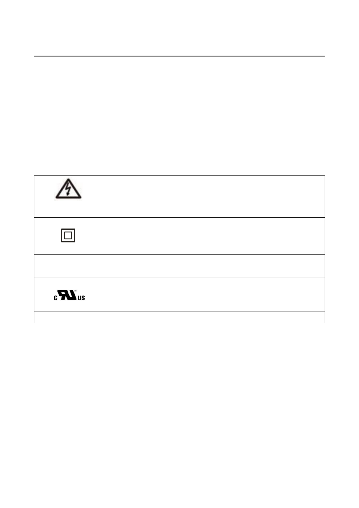
Markings on the product
HIGH VOLTAGE:
The product works with high voltages. All work on the product must only be
performed as described in this document.
DOUBLE INSULATION:
The product protected throughout by Double Insulation.
CAT III MEASUREMENT CATEGORY:
MEAS REMENT CATEGORY is CATEGORY III .
UL MARK:
The product is approved by L certification.
3

Ⅱ,Product Brief
FR-DCMG is mainly used in the PV combiner box in PV power plants, to monitor the working
status of every PV string and send the status data to the monitor center of the PV power plant
through field bus or industrial wireless. Also a new function is detect arc fault in PV string or
DC bus-bar. If detected the arc fault, the main unit with send cut-signal to power unit to drive
the shunt tripping device. Then the current will cut-off, and avoid fire happen.
Main Features
•Arc fault detect: detect arc fault in PV string by channel and bus-bar.
•Monitoring: the current of every PV string, PV bus voltage, combiner box
temperature, status of SPD, status of DC circuit breaker.
•Support isulation leakage current monnitoring.
•Communication interfaces: Modbus RTU RS485 or robust industrial wireless.
•Max supports 24 channels PV string in Modbus communication mode, 20
channels of PV string in industrial wireless communication mode.
•ocal CD display. FR-DCMG supports current histogram display.
Block diagram:

FR-DCMG DC System Monitor User Manual Fonrich New Energy Technology Co., td.
Mechanical Dimensions & Structure
FR-DCMG-MMPA /FR-DCMG-MMPB /FR-DCMG-MMPT Main Unit
5
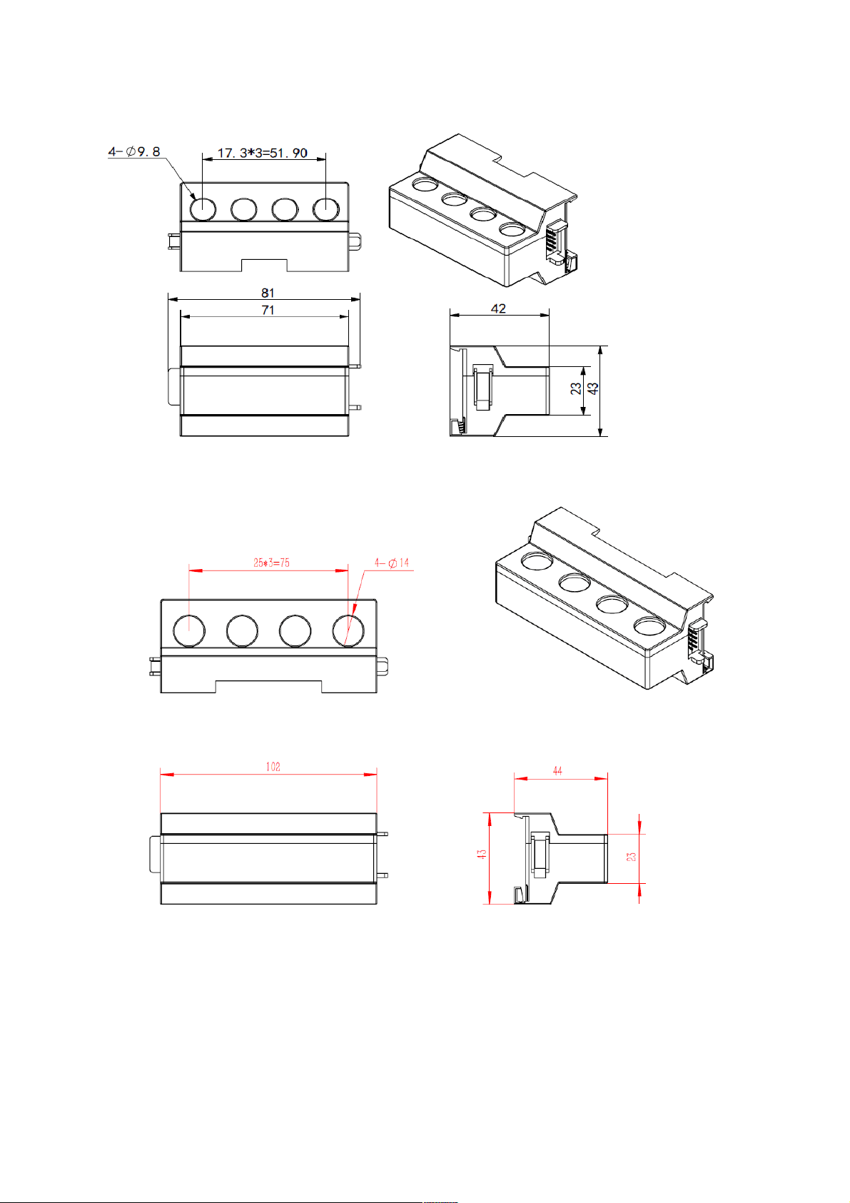
FR-DCMG-HS4A /FR-DCMG-AS4A Hall Current Sensor
FR-DCMG-HS4T /FR-DCMG-AS4T Hall Current Sensor

FR-DCMG DC System Monitor User Manual Fonrich New Energy Technology Co., td.
FR-PVMA-LHSA Leakage Current Sensor
FR-PVMG-SHTPA /FR-PVMG-SHTPT S unt Trip Power Unit
7
Ⅳ, Connection of Modules and Definition of the Terminals
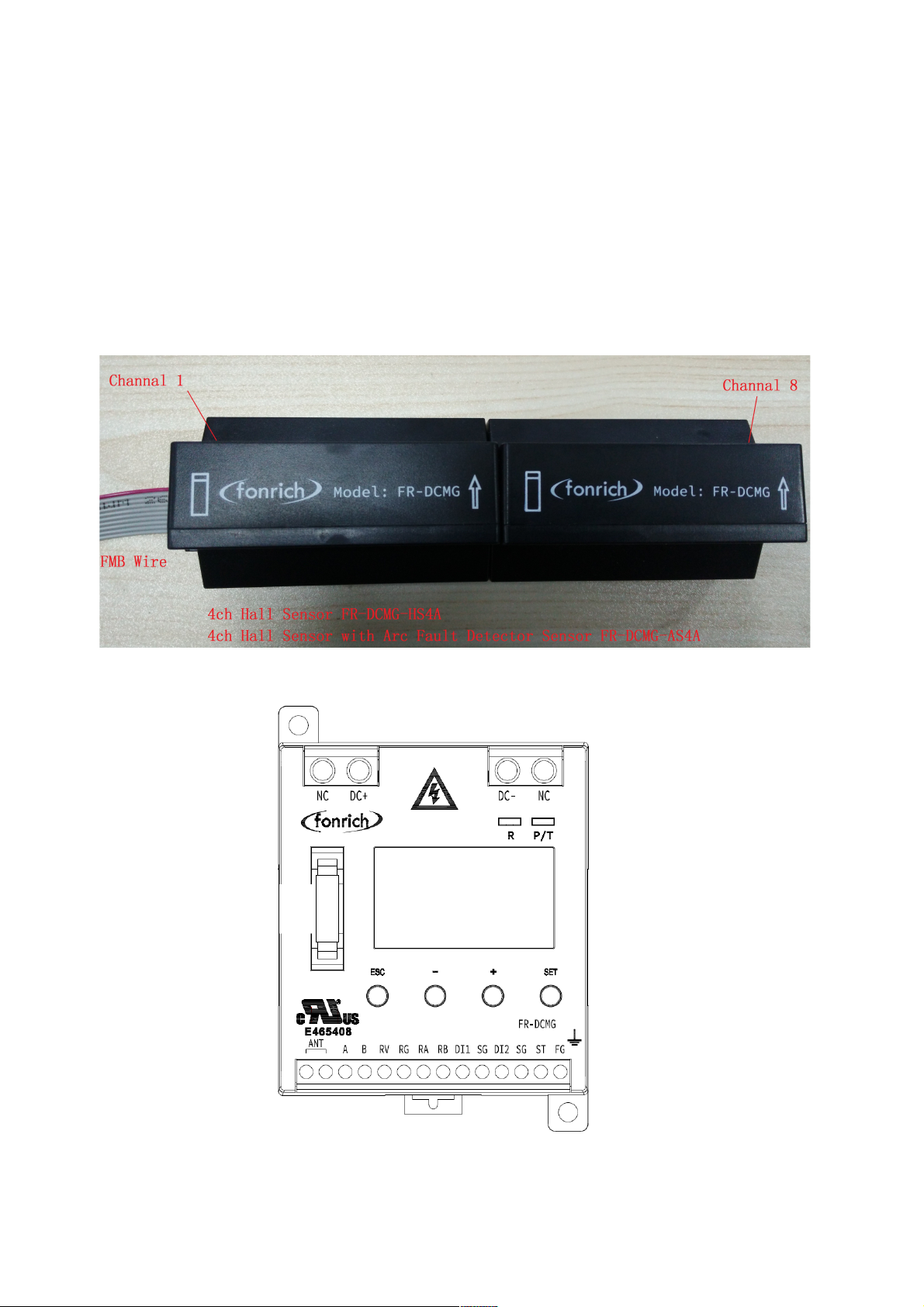
Connection of the hall sensor module
FR-DCMG-HS4A, FR-DCMG-AS4A connect in the way of concatenation, support 4~24
channels current monitoring. Specific connection and instruction refer to the pictures
below(take 8 channels as example, the nearest FMB wire is channel 1):
FR-DCMG-MMPA /FR-DCMG-MMPB /FR-DCMG-MMPT Main Unit
FMB B s
Connector
FR-DCMG DC System Monitor User Manual Fonrich New Energy Technology Co., td.
Symbol Definition of the symbol
DC+、DC- PV DC bus power supply terminals
NC No connection
FG Field Ground terminal
TS External temperature sensor terminal
SG Temperature and digital input common terminal (Signal Ground)
DI1、DI2 Digital Input terminals
A、B Modbus communication terminals
RV、RG Power supply of the RTM bus
RA、RB Communication terminals of the RTM bus, for driver signal if need
shunt tripping coil
ANT SMA wireless antenna port/No connection
FMB bus Port of the FMB bus
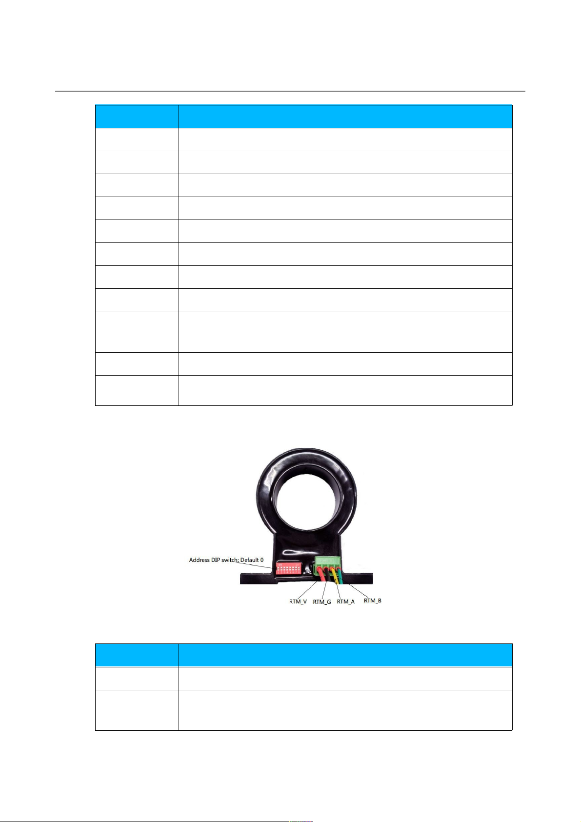
FR-PVMA-LHSA Leakage Current Sensor
Symbol Definition of the symbol
RTM_V, RTM_G Power supply from Main Unit, wire to RV, RG terminals in main unit
RTM_A, RTM_B Communication terminals of the RTM bus, wire to RA, RB terminals
in main unit
9
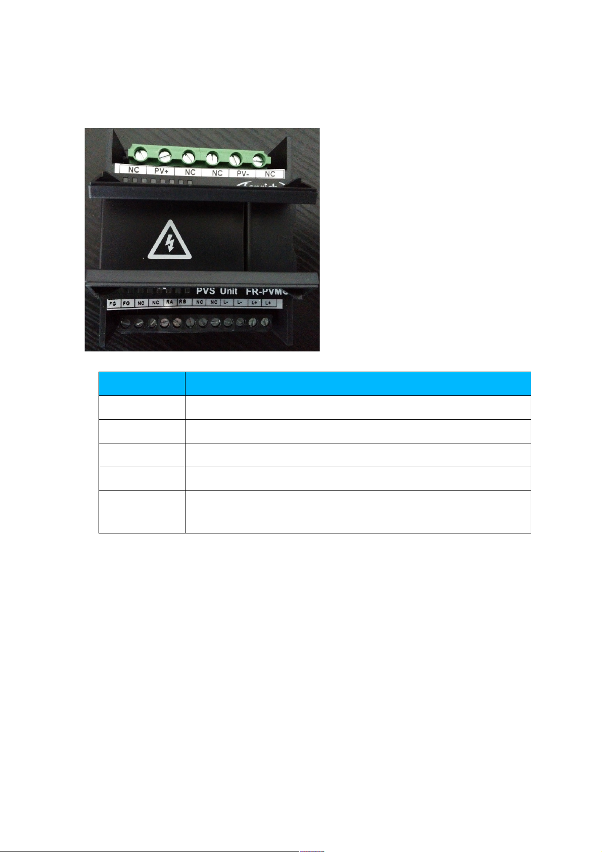
FR-PVMG-SHTPA /FR-PVMG-SHTPT S unt Trip Power Unit
Symbol Definition of the symbol
PV+、PV- PV DC bus power supply terminals
NC No connection
FG Field Ground terminal
RA、RB Drive terminal from main unit
+, - Drive Out terminal, wire to shunt trip coil, the level is 25VDC, max
power is 80W in 10ms
Earth connection
The FG terminal of the FR-DCMG main unit and power unit must be connected to the
field ground otherwise the communication will be disturbed, and the reliability of the
device will decrease. The FG terminal must connect to the nearby earth ground and the
wire that connects FG terminal to bottom board of the combiner box should not be longer
than 15cm, less than 10cm is great and the wire should be coarse enough. The bottom
board of the combiner must connect to the field ground.
FR-DCMG DC System Monitor User Manual Fonrich New Energy Technology Co., td.
Ⅴ, Local Operation
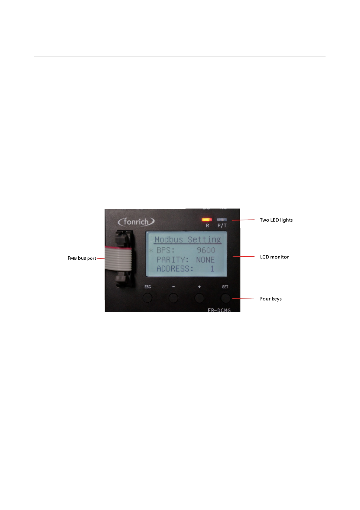
Instruction of buttons operation and display interface
FR-DCMG has four key buttons:“ESC”、“-”、“+”、“SET”. The key “ESC” is used
to return to the default interface or cancel the setting of parameters. The key “SET” is used to
enter the parameter setting interface, chose the parameter that to be configured, or confirm
the setting. The keys“+”and”-”is used to scroll the screen, or adjust the value of the
parameters. Press the keys “SET” and “ESC” at the same time will enter the mode select
interface. If no key is pressed in 15 seconds, the CD will jump to the default interface and the
brightness of backlight will decrease. If the key “ESC” is pressed, the interface will jump to the
default interface immediately.
FR-DCMG supports the histogram display of the detected current, digital display of the
detected current and generated energy, parameters' setting interface, the wireless node state
interface in the FWB GATEWAY mode. The plentiful interfaces make it convenient to operate the
device. Here is the description of every mode and the interface in the below.
Mode setting
When FR-DCMG is powered up, the P/T light will be bright to show that the device is
working then the CD monitor will come up with the OGO picture for about 5 seconds.
11
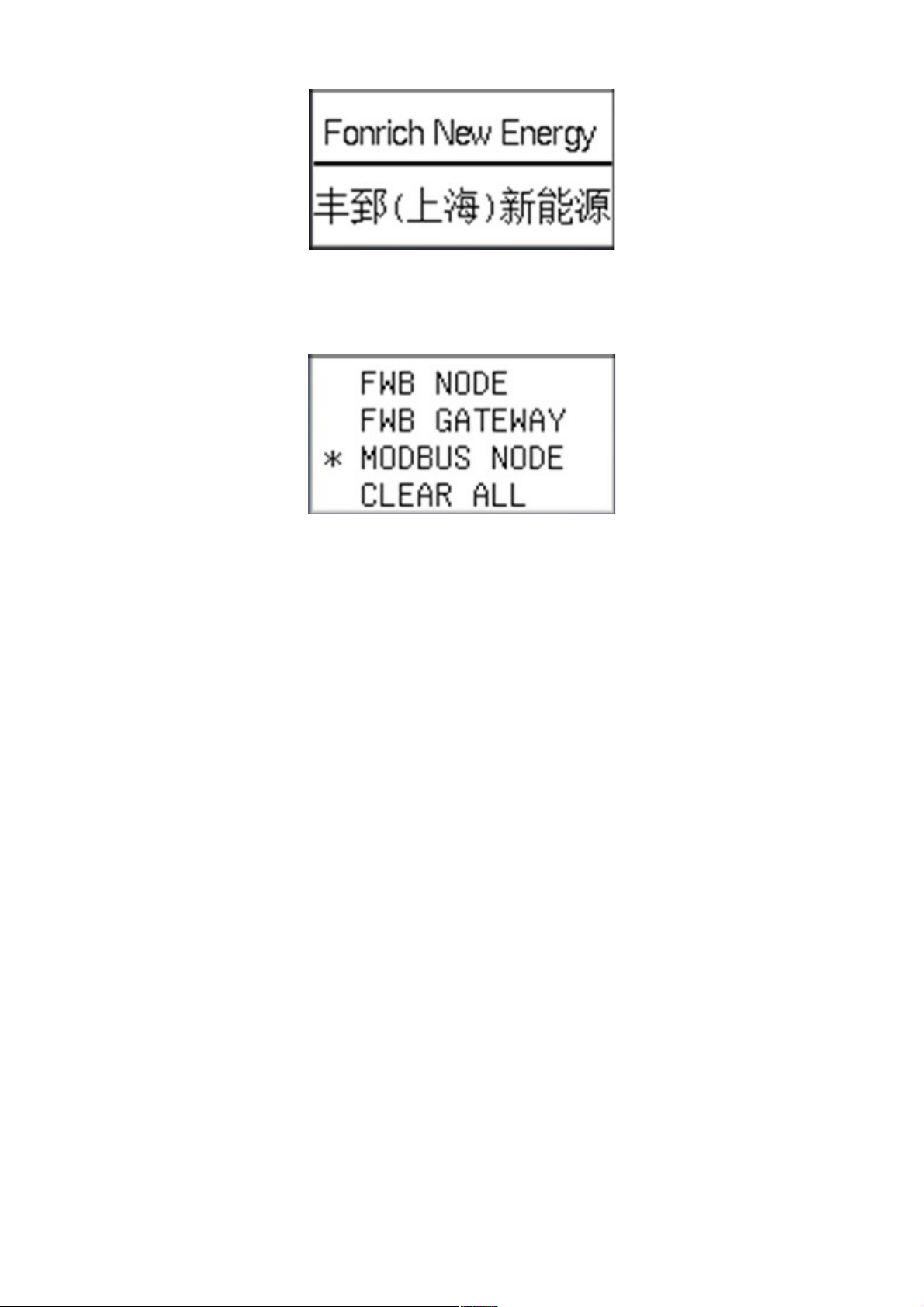
When the OGO disappears FR-DCMG enters the relative mode, if keys “ESC”and “SET”
are pressed in the same time, FR-DCMG enters the mode selecting interface as below :
Among which
“*”: The selecting cursor that can be moved through pressing “+” and “-”keys.
FWB NODE:Actually, it is a wireless client mode. FWB means Field Wireless Bus, which
is robust filed wireless communication protocol designed by Fonrich. In this mode, the modbus
interface is also active.
FWB GATEWAY:In this mode the device is the wireless gateway of FWB network. In
this mode, the modbus interface is also active.
MODBUDS NODE:In this mode, only the modbus interface is active, and the wireless
is disabled.
C EAR A :Actually, it is not a work mode, which is just used to clear the generated
energy data that stored in the device in past.
When a different mode is selected and the key “SET” is pressed, the device will reboot to
enter the selected mode. If the previous mode is MODBUS mode then the parameters of the
modbus communication will be reserved for modbus communication.
MODBUS mode
The default mode of the device is MODBUS mode, when communicate with PC through
RS485, the ED lights R and P/T will twinkle to indicate that the communication is normal.
Histogram interface
The histogram interface will come up after the interface of OGO, histogram interface is the
FR-DCMG DC System Monitor User Manual Fonrich New Energy Technology Co., td.
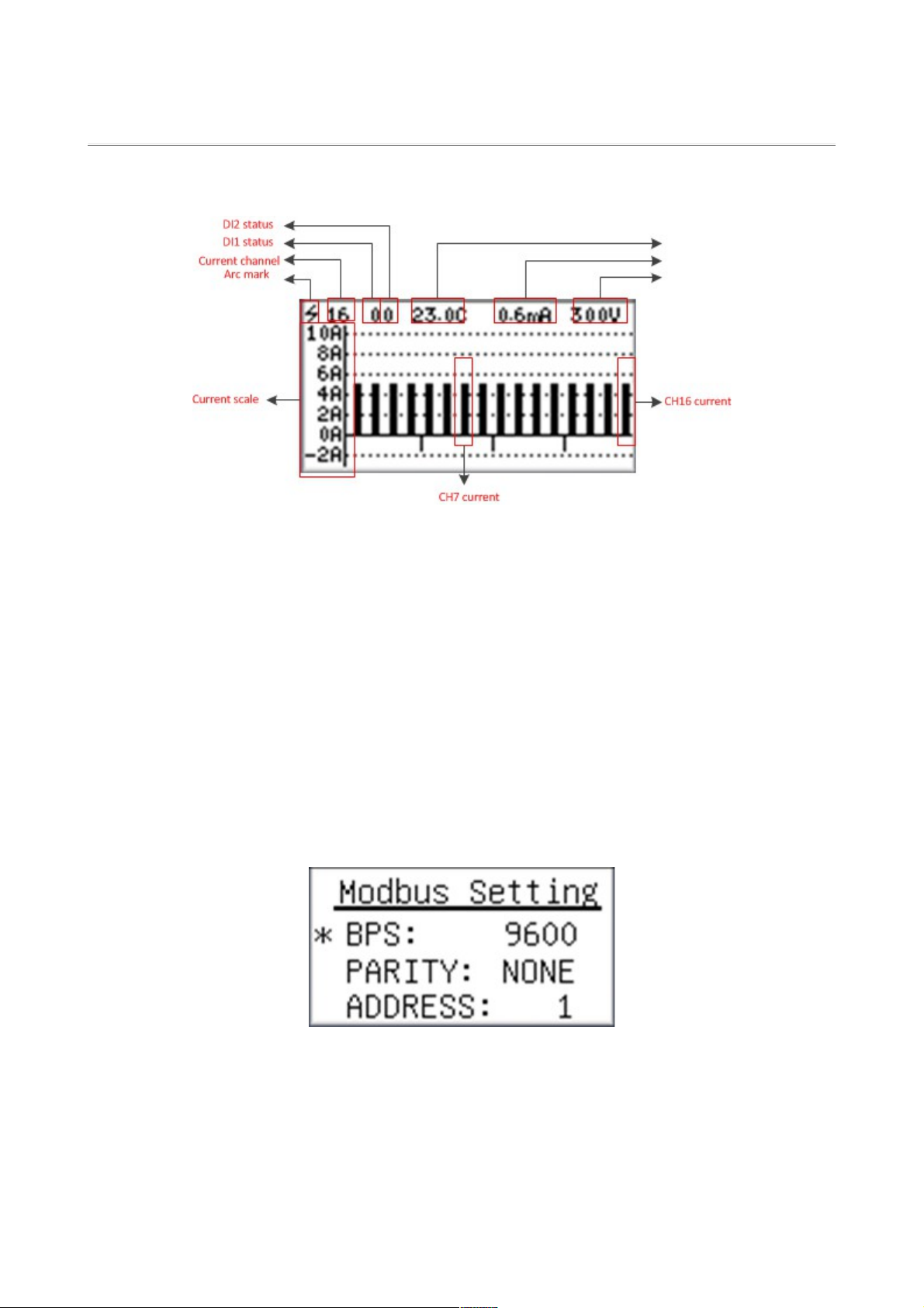
default interface of MODBUS mode, it will be shown like below:
The histogram shows the current value of every channel, the current value ranges from -2A to
10A. For the hall sensors are four channel sensors, so in the histogram every four channels will
be indicated from another four channels which means that from left to right is channels 1-4,
channels 5-8, channels 9-12 and so on. If there is no button operations in 15 seconds, the
brightness of the CD will decrease.
If the 'Arc mark' is show, it means the current sensor is with Arc Fault Detect.
Parameters setting interface
When the key “SET” is pressed in the histogram interface the device will enter MODBUS
parameter setting interface, the device can communicate through RS485 in the other two mode
also but the modbus related parameter should be set in the MODBUS mode. MODBUS
parameter setting interface comes up as below:
Among which
BPS:MODBUS communication baud rate , the selectable rate are 2400、 4800、
9600(default rate), 19200、38400.
13

PARITY: The parity of MODBUS communication, the selectable parity none
parity(NONE), odd parity(ODD), even parity(EVEN)(default none parity).
ADDRESS: The address of the MODBUS slave device, ranges from 1 to 247(default 1).
Digital displaying interface
When the key “+” or “-” is pressed in the histogram interface, the digital display
interface will come up to show the current values and generated energy values. When firstly
press key “+” then firstly shows the current value of the first four channels, when firstly press
key “-” then firstly shows the generated energy of the last four channels. Then go on pressing
the “+” or “-” key will scroll the screen to show current or generated energy value of other
channels. The generated energy value will come up at the end of current value, the current
value will come up after generated energy value on the reverse direction. Note that the top line
is the same with histogram interface.
Interface of the digital current:
Interface of the digital generated energy:

FR-DCMG DC System Monitor User Manual Fonrich New Energy Technology Co., td.
FWB NODE mode
Select FWB NODE mode in the mode selecting interface, if the previous mode is not FWB
NODE mode, the device will reboot after pressing the key “SET”, and the device will enter
FWB NODE mode.
Histogram interface
The histogram interface will come up after the interface of OGO, histogram interface is
also the default interface of FWB NODE mode, it will be shown the same as the MODBUS mode.
Parameters setting interface
When the key “SET” is pressed in the histogram interface the device will enter FWB NODE
parameter setting interface. FWB NODE parameter setting interface comes up as below:
Among which:
ADDRESS:the address of the wireless node, every device in FWB NODE mode will
get an unique address in the frequency indicated by FREQ, the address ranges
from 1 to 216.
FREQ:the frequency that the device used to communicate with other device, ranges
from 900MHz to 928MHz, step by 200KHz.
Digital displaying interface
When the key “+” or “-” is pressed in the histogram interface, the digital playing
interface will come up, which is the same as digital playing interface in MODBUS mode.
FWB GATEWAY mode
Select FWB GATEAY mode in the mode selecting interface, if the previous mode is not FWB
GATEWAY mode the device will reboot after the pressing of the key “SET”, and the device
enter FWB ATEWAY mode. When communicate with PC through RS485, the ED lights R and
15
P/T will twinkle to indicate that the communication is normal.
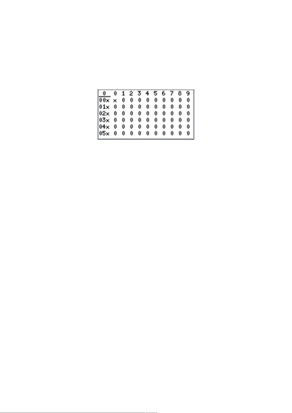
Wireless node connecting status interface
The wireless node connecting status interface will come up after the interface of OGO,
wireless node connecting status interface is the default interface of FWB GATEWAY mode, it will
be shown as below:
The number 1 on the left side of the top line means the online number of wireless node,
the address is composed by the numbers in the left column except the top “1” and the top
row also except the left “1”, calculate like :
address = xx(xx*) * 10 + x (x in the top row beside “1”)
take the upper picture as example, the supported number of wireless node is 30 for the
position whose address that bigger than 30 shows nothing but blank, there are one node
online, whose address is 01(01*) * 10 + 0 = 10 the position of the address shows the state of
the wireless node, 1 means the node is online and the distance to gateway is 1, 0 means that
the node is offline. Note that the distance dose not means the real distance, it just indicate that
weather the node need route transfer to communicate with gateway. Note that if the
supported number of wireless node is bigger than 60, you need scroll the screen to check the
state of the last node.
Histogram interface
The histogram interface will come up when press the key “+” till the end of wireless node
connecting state interface, if the supported number of the wireless node is less than 60 the
histogram interface will come up as soon as the key “+”is pressed. The histogram interface
will be shown the same as the MODBUS mode.
Digital displaying interface
When the key “+” or “-” is pressed in the histogram interface, the digital playing
interface will come up, which is the same as digital playing interface in MODBUS mode.
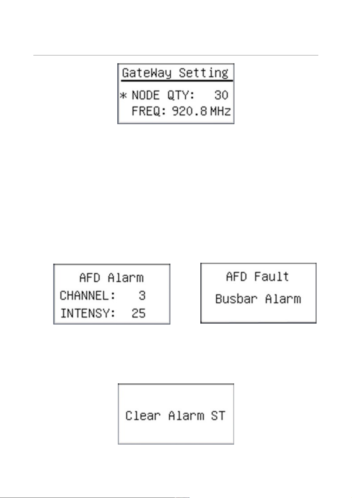
Parameters setting interface
Press the key “SET” in wireless node connecting state interface will enter FWB GATEWAY
setting interface which will be shown as below:
FR-DCMG DC System Monitor User Manual Fonrich New Energy Technology Co., td.
Among which:
NODE QTY:the supported number of the wireless node by this gateway, default 30
ranges from 1 to 216. Generally, please keep this number as less as possible, because the
communication cycle will become longer as this number growing.
FREQ: the frequency that the device used to communicate with other devices
ranges from 315MHz to 928MHz, step by 200KHz.
Arc Fault Detect Alarm Function
Arc Fault Detect Alar picture
When the arc fault detected, the picture will change to alarm picture, which will shows as
below:
Channel Arc Fa lt B s-bar Arc Fa lt
It shows that: The CH3 has arc fault, the arc intensity is 25.
The arc intensity is a value means arc dangerous level. The default threshold value is 40.
If arc fault has excluded, it is necessary to reset the alarm picture. Press “ESC”key and
keep it abort 5 seconds.
17

Then the picture will change to histogram picture.
Shunt Tripping Setup Interface
At default picture, press key “ESC” and “+”in same time, will change to “Shunt
Tripping” set interface, shows as below:
Among which:
“TIME”: Set the shunt trip drive hold time, the shunt trip drive signal will be enable
when alarm event occurs, and hold on set time, then disable shunt trip drive signal.
“SE FCHECK”: If will start self check arc fault function. Check the arc sensor status
and check shunt tripping coil.

FR-DCMG DC System Monitor User Manual Fonrich New Energy Technology Co., td.
Ⅵ, Definition of the Modbus Protocol
Configuration of the modbus
Modbus communication mode:RTU mode
Address of the slave device:range from 1 to 247 (default 1)
Baud rate:(bps) 2400、4800、9600(default)、19200、38400
Parity of the byte:odd parity、even parity、none parity(default)
Description of the modbus frame
The byte in the communication frame composed by 1 start bit, 8 bits data bit, 1 parity bit, 1
stop bit like the below table(Refer to standard modbus RTU protocol):
Address code Function code Data field CRC field
1 byte 1 byte N*1byte 2 bytes
The address code is the slave device address. The function code tell the slave device how to
respond, and what request of the slave device response. N in data field can not be bigger than
252, the CRC field used to check the frame by using cyclic redundancy check.
Description of the function codes
FR-DCMG supports almost all function codes, includes 01, 02, 03, 04, 05, 06, 15 and 16. These
modbus function codes are separated to two kinds of operation: bit operation and word
operation. In FR-DCMG modbus implementation, all bit operations with different function
codes share same bit register address mapping, and all word operations with different function
codes share same word register address mapping.
Read and write operations of the registers in bit
•Function code 01 used to read the content of bit-type registers
•Function code 02 used to read the content of bit-type registers
19

•Function code 05 used to write single bit-type registers
•Function code 15 used to write multiple bit-type registers
the content of the bit-type register could be switches alarm information etc.
Read and write operations of the registers in word
•Function code 03、04 are used to read multiple word-type registers
•Function code 06 is used to write single word-type registers.
•Function code 16 is used to multiple word-type registers。
The content of the word-type registers can be voltage, current, generated energy, etc.
Description of the registers
Description of the registers in bit
Bit address Functional description remark
Input switches and alarm signal(only Available to function code 02 )
0x0000 Digital input 1 status, DI1 The input switch DI1 of the device(0:break,1:
close)
0x0001 Digital input 2 status, DI2 The input switch DI2 of the device(0:break,1:
close)
0x0011 External temperature high alarm When the external temperature is higher than the set
value, set to 1
0x0020 Voltage too high alarm When the detected voltage is bigger than the set
value, set to 1
0x0021 Voltage too low alarm When the detected voltage is smaller than the set
value, set to 1
0x0030 Channel 1 no current alarm When current value equal to 0, set 1
0x0031 Channel 1 current too low alarm When current value smaller than the set value but not
equal to 0, set 1
0x0032 Channel 1current too high alarm When current value bigger than the set value, set 1
0x0033 Channel 2 no current alarm When current value equal to 0, set 1
0x0034 Channel 2 current too low alarm When current value smaller than the set value but not
equal to 0, set 1
This manual suits for next models
3
Table of contents
Other Fonrich Measuring Instrument manuals


