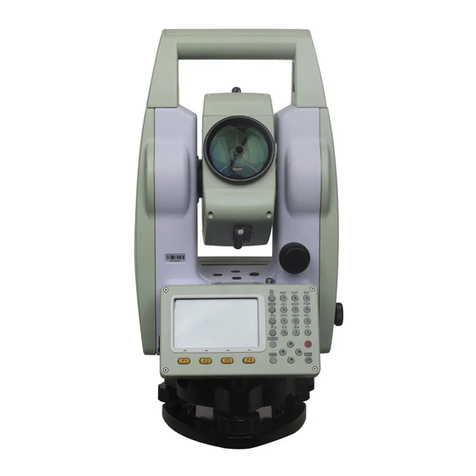
Hi-Target ZTS-720 Series User manual

Android Total Station ZTS-720
Series
Instruction manual

Preface
Instruction manual use
Welcome to use Zhongda Androidid total station ZTS-720 series
instruction manual, this manual describes how to set up and use ZTS-
720 series total station, in order for you to use the product better,
please make sure to read this product instruction manual carefully, the
sample pictures and icons in the manual are different from the actual
product, please take the actual product as the standard. You can
contact our local sales office.
Instruction Manual Introduction
This manual is to guide you how to work with the mainframe of ZTS-720
series of Total Station by taking Zhongda Androidid Total Station ZTS-
720 as an example.
Experience Requirements
In order to use Zhongda Androidid Total Station ZTS-720 better,
Zhongda recommends you to have some measurement knowledge and
read this manual carefully. If you have any questions, please refer to
the official website of Zhongda: www.hi-target.com.cn.
Safety technology tips
Note: Note that the contents of the tips are generally operating special
places that require your special attention, so please read them
carefully.
Warnings: The contents of the warnings are generally very important
tips. Failure to follow the warnings will result in damage to the
instrument, loss of data, and system crashes, and may even
endanger personal safety.
Liability Waiver
Before using this product, please be sure to read the instruction manual

carefully, which will help you to use this product better. Zhong Haida is
not responsible for any damage caused by your failure to operate the
product in accordance with the requirements of the instruction manual,
or your misuse of the product due to failure to properly understand the
requirements of the instruction manual.
Hi Target is committed to continuously improving the functions and
performance of its products and the quality of its services, and reserves
the right to make changes to the contents of the instruction manual
without prior notice.
We have checked the content of the printed materials and the
consistency of the hardware and software, but do not exclude the
possibility of deviation, the pictures in this manual are for reference
only, if there is any discrepancy with the actual product, please take the
actual product as the standard, the final interpretation right belongs to
Suzhou Xunwei.
Technology & Services
If you have any technical problems, you can contact the technical
center of each branch or the technical department of the headquarters
by phone, and we will answer your questions promptly.
Related Information
You can find the manual by.
1、Login the official website of Zhongda, you can find it in "Service
Center" → "Download" → "Manual".
Your suggestions
If you have any suggestions and comments on this manual, please
contact us, your feedback will be a great improvement to the quality of
our manual.

Total Station ZTS-720 series instruction manual
V
Table of Contents
Instrument features and uses ..................................................................................1
Instrument Features........................................................................................2
Instrument use.................................................................................................3
Cautions...........................................................................................................3
Security Guide .................................................................................................5
Name and function of each part of the instrument ...................................................7
Name of each part ...........................................................................................8
Keyboard functions and information display ...............................................9
Preparation before measurement ..........................................................................11
Instrument unpacking and storage..............................................................12
Placement of instruments ............................................................................12
Battery loading and unloading, information and charging........................15
Reflective Prism ............................................................................................16
Loading and unloading of the base .............................................................16
Telescope eyepiece adjustment and target illumination............................16
Alphanumeric input method.........................................................................17
USB flash drive notes ...................................................................................19
Instrument Registration................................................................................19
Instrument data storage size prompt message notes................................21
Software Introduction and Easy Operation Procedure...........................................22
Software Introduction ...................................................................................23
Software Installation .....................................................................................23
Quick Start .....................................................................................................23
Basic measurement...............................................................................................30
Coordinate measurement .............................................................................31
Coordinate placement...................................................................................33
Set up stations.......................................................................................................35
Survey station rear view ...............................................................................36
Rear view inspection.....................................................................................39
Rear rendezvous ...........................................................................................40

Total Station ZTS-720 series instruction manual
VI
Elevation Transfer .........................................................................................43
Point to linear set up station ........................................................................46
Collection procedure..............................................................................................48
Coordinate measurement .............................................................................49
Single pitch eccentric ...................................................................................49
Plane eccentricity..........................................................................................50
Cylindrical eccentric .....................................................................................51
Side to side measurement............................................................................53
Overhang height measurement....................................................................55
Line and extension point measurements....................................................58
Line and corner point measurement ...........................................................59
Proofing procedure ................................................................................................61
CAD Release..................................................................................................62
Coordinate placement...................................................................................67
Image-assisted release .................................................................................69
Angular distance release..............................................................................70
Directional line placement............................................................................72
Straight Line Plotting ....................................................................................73
Reference line placement .............................................................................74
Reference Arc Release..................................................................................76
Calculation tools ....................................................................................................84
Unknown point orientation correction ........................................................85
Orientation-free calibration ..........................................................................86
Coordinate orthogonal calculation ..............................................................89
Coordinate backcalculation..........................................................................90
Area perimeter ...............................................................................................91
Angle conversion ..........................................................................................92
Distance conversion .....................................................................................93
Point average.................................................................................................93
Slow curve calculation..................................................................................94
Line segment equipartition...........................................................................95
Calculators.....................................................................................................96

Total Station ZTS-720 series instruction manual
VII
Project Management .............................................................................................97
Project Management .....................................................................................98
Point Library ................................................................................................100
Legend Code................................................................................................107
Road.................................................................................................................... 111
Road Design ................................................................................................112
Line Calculation...........................................................................................129
Road Release...............................................................................................129
Structure release .........................................................................................132
Bridges ...............................................................................................................135
Pier formwork library ..................................................................................136
Bridge arrangement ....................................................................................138
Cone slope design library...........................................................................140
Pier placement.............................................................................................142
Cone Slope Release ....................................................................................144
Tunnel..................................................................................................................147
Tunnel section bank....................................................................................148
Tunnel Feature Points.................................................................................152
Tunnel over-under-excavation ...................................................................154
Configuration .......................................................................................................157
Distance measurement parameters configuration ...................................158
Total Station Configuration ........................................................................161
Measurement aid configuration .................................................................162
Unit/Display Configuration .........................................................................164
Total Station Calibration .............................................................................168
Total Station Information & Registration...................................................168
Quick Menu .........................................................................................................171
Laser down to point ....................................................................................172
Atmospheric Correction .............................................................................173
Prismatic constant ......................................................................................173
Scoreboard lighting ....................................................................................174
Custom Function Keys ...............................................................................174

Total Station ZTS-720 series instruction manual
VIII
FTP ...............................................................................................................175
Total station registration/connection.........................................................176
Top shortcut function ...........................................................................................178
Distance measurement mode.....................................................................179
Tilt compensation........................................................................................179
Reflector type switching.............................................................................179
Laser pointing..............................................................................................179
Point Data ....................................................................................................180
More..............................................................................................................180
Inspection and calibration....................................................................................182
Tube level.....................................................................................................183
Round level..................................................................................................183
Telescope dividing plate.............................................................................183
Perpendicularity of the visual alignment axis to the horizontal axis......184
Vertical disc indicator zero point automatic compensation ....................185
Vertical indicator difference (i-angle) and vertical indicator zero point
setting ..........................................................................................................186
Aligner ..........................................................................................................188
Instrument addition constant (K) ...............................................................189
Parallelism of the optic alignment axis and the emitting electro-optical axis
......................................................................................................................190
Prism-free distance measurement.............................................................190
Appendix A Symbol Meanings .........................................................................192

Total Station ZTS-720 series instruction manual
1
Instrument features and uses
This chapter introduces.
▪ Instrument Features
▪ Instrument use
▪ Precautions
▪ Security Guidelines
C H A P T E
R
1

Total Station ZTS-720 series instruction manual
2
Instrument Features
Feature-rich - this series of total station based on Androidid hardware platform,
support angle measurement, distance measurement, key light, serial port, Bluetooth,
WiFi, USB, automatic tilt compensation, alignment height, key tone, support GNSS
equipment installed at the same point, support total station command communication
protocol (Xunwei L protocol and T protocol). With powerful industry application
software, including project management, station setting, basic measurement,
program measurement, road release, bridge, tunnel, map, configuration. At the same
time, it can be installed to the handheld mobile use, WiFi connection total station
remote control measurement, suitable for a variety of professional measurement.
1、Absolute digital dial
Equipped with an absolute digital dial, the instrument can measure directly when
it is turned on. The azimuth information is not lost even if the power is reset in the
middle of the process.
2、Powerful memory management
Large memory capacity and easy file system management for data addition,
deletion, transfer, etc.
3、Prism-free distance measurement
This series of total stations all come with prism-free ranging function of laser
ranging, which can directly measure objects of various materials and different colors
(such as walls of buildings, poles, wires, cliff walls, mountains, mud, stakes, etc.) at a
long distance, quickly and with high accuracy. For those targets that are not easy to
reach or simply inaccessible, the application of prism-free ranging function can
complete the measurement task very well.
4、Special measurement procedures
In addition to the common basic measurement functions, this series of total
station also has special measurement programs for overhang height measurement,
eccentric measurement, edge-to-edge measurement, release sampling, rear
rendezvous, area calculation, road design and release, etc., which can meet the
needs of professional measurement.
5、Interchangeable eyepieces
The eyepiece of this instrument is interchangeable eyepiece, which can be
conveniently equipped with bent tube eyepiece, so that it is easy for users to observe
the zenith direction and the measurement of high-rise buildings.

Total Station ZTS-720 series instruction manual
3
6、Laser down to point optional
Convenient station indication function for easy station setting.
7、Image assisted release
The instrument is equipped with image assisted release function, which can
display the point mark of release point in the software interface to facilitate the
alignment of the release point.
Instrument Use
Total station is a measuring instrument that measures azimuth, target distance,
and can automatically calculate the coordinates of target points. It has an important
role in economic construction and national defense construction. Mineral census,
exploration and extraction, construction of railroads, highways, bridges, agricultural
water conservancy, urban planning and construction, etc. are inseparable from the
electronic total station measurement. In national defense construction, such as
battlefield preparation, harbor, fortress, airport, base and military engineering
construction, etc., all must be based on detailed and correct geodesy . In recent
years, the electronic total station has become an effective tool for precision
positioning and installation in large precision engineering measurements,
shipbuilding and aviation industries.
The angle measuring part of this series total station adopts absolute coding
digital angle measuring system, and the distance measuring system adopts
integrated circuit control board distance measuring head, using Androidid system,
with measuring software, it can display the measurement results of horizontal angle,
vertical angle, slope distance and flat distance, height difference, coordinates, etc. at
the same time, and it can measure angle and slope in many modes.
Prism-free rangefinding is even designed for users of engineering projects,
especially suitable for various construction fields. It can be widely used for three-
dimensional coordinates of buildings, position determination, overhang height
measurement, plumbness determination, pipeline positioning, section measurement,
etc. It is also suitable for triangulation control measurement, topographic
measurement, cadastral and property measurement, etc.
Cautions
1, daylight measurement should be avoided when the objective lens is aimed
directly at the sun. It is recommended to use a solar filter to diminish this effect.
2、Avoid storing the instrument at high and low temperatures and using the

Total Station ZTS-720 series instruction manual
4
instrument when there is a sudden change in temperature.
3、When the instrument is not in use, it should be put into a box, placed in a
ventilated and dry place, and pay attention to shock-proof, dust-proof and moisture-
proof.
4、If the temperature at the working place of the instrument is too different from
the temperature at the storage place, the instrument should be left in the box first
until it adapts to the ambient temperature and then take out the instrument for use to
obtain good accuracy.
5、If the instrument is not used for a long time, the battery should be removed
and stored separately. And the battery should be charged once a month to extend
the life of the battery.
6、The instrument should be packed in a box when transporting, and be careful
during transportation to avoid extrusion, collision and violent vibration. It is better to
use soft cushion around the box for long-distance transportation.
7、When setting up the instrument, use high-quality wooden stand as far as
possible to ensure the stability of the measurement to improve the accuracy of the
measurement.
8, in order to improve the accuracy of prism-free measurement, please be sure to
keep the object lens clean. Exposed optics need to be cleaned, the application of
degreasing cotton or lens paper gently wipe clean, do not use other items to wipe.
9、After using the instrument, use a lint cloth or brush to remove the dust on the
surface of the instrument. After the instrument is wet by the rain, do not power on,
should be clean and soft cloth dry and put in a ventilated place for a period of time,
so that the instrument fully dry before use or box.
10, before the operation should be carefully and thoroughly check the instrument,
to determine the instrument indicators, functions, power, initial settings and correction
parameters are in line with the requirements before the operation.
11、If the instrument function is found to be abnormal, non-professional
maintenance personnel should not disassemble the instrument without permission to
avoid unnecessary damage.
12、The prism-free total station emits laser light, which cannot be directed at the
eyes when used.

Total Station ZTS-720 series instruction manual
5
Note: This instrument is subject to strict inspection and calibration at the
factory, and the quality meets the standard requirements. But the
instrument after long-distance transport or environmental
changes, the instrument's optical and mechanical structure
parameters of trace changes are inevitable. Therefore, the new
purchase of this instrument and to the measurement area before
the operation of the instrument should be carried out in this
section of the inspection and calibration to ensure the accuracy of
the results of the operation.
Security Guide
When using prism-free laser distance measurement, it is important to pay
attention to the following safety matters.
Warning.
The total station is equipped with laser class 3R/IIIa rangefinder.
This product is a Class 3R laser product, according to the following standards.
IEC 60825-1:2001 "Radiation safety of laser products".
For Class 3R/IIIa laser products, the emission limit at wavelengths of 400nm-
700nm can be achieved within five times that of Class 2/II.
Warning.
Continuous direct vision of the laser beam is hazardous.
Prevention.
Do not stare at the laser beam with your eyes or point the laser beam at others.
The reflected beam is a necessary measurement signal for the instrument.
Warning.
When a laser beam is directed at, for example, a prism, a flat mirror, a metal
surface, or a window, direct viewing of the reflected light with the eye can be
dangerous.
Prevention.
Do not stare at the laser reflection. Do not look next to the laser light path or prism
when the laser switch is on (ranging mode). Only look through the telescope of the

Total Station ZTS-720 series instruction manual
6
total station to illuminate the prism.
Warning.
Improper use of Class 3R laser equipment can be dangerous.
Prevention.
To avoid causing injury and to allow each user to take practical safety precautions,
control must be done within the distance of possible hazards (according to the
standard IEC60825-1:2001).
The following is an explanation of the main parts of the criteria.
Class 3R laser products for outdoor and construction site use (prism-free
measurement)
a Only persons who have received the relevant training and certification may
install, commission and operate such laser equipment.
b Set up the corresponding laser warning signs within the use area.
c To prevent anyone from looking directly into the laser beam with their eyes or
using optical instruments to view the laser beam.
d To prevent laser damage to people, the laser beam should be blocked at the
end of the working route. The laser beam must be terminated when there is human
activity within the restricted area (harmful distance*) through which the laser beam
passes.
e The path of the laser beam must be set above or below the human line of sight.
f laser products when not in use, properly stored for safekeeping, not certified
people should not use.
g To prevent the laser beam from unintentionally irradiating such as flat mirrors,
metal surfaces, windows, etc. Be especially careful of surfaces such as flat mirrors
and concave mirrors.
*The harmful distance is the maximum distance from the start of the laser
beam to the point where the laser beam weakens to the point where it will not cause
harm to a person. For built-in rangefinder products with Class 3R/IIIa lasers, the
harmful distance is 1000m (3300ft), beyond which the laser intensity is reduced to
Class 1 (no harm to the eye from visualizing the beam).

Total Station ZTS-720 series instruction manual
7
Name and function of each part of the
instrument
This chapter introduces.
▪ Name of each part
▪ Keyboard functions and information display
C H A P T E
R
2

Total Station ZTS-720 series instruction manual
8
Name of each part
The names of the product components are as follows.
1 - coarse sight; 2 - objective lens focusing screw; 3 - vertical fine adjustment screw;
4 - display; 5 - eyepiece; 6 - battery compartment cover.
7 - Base; 8 - Vertical brake screw.
Figure 2-1
9-Type C USB port/SD card slot/external SIM card slot; 10-Quick measurement
button; 11-objective lens; 12-camera
13 - Horizontal trim screw; 14 - Horizontal brake screw.
1
2
5
3
4
7
6
8
9
10
11
12
13
14

Total Station ZTS-720 series instruction manual
9
Figure 2-2
Keyboard functions and information display
Figure 2-3
Table 2.1 Key functions.
Button
Name
Function
Quick
measurement
keys
Configurable measurement/deposit mode, triggers
a measurement/deposit when clicked.
Power Switch
Controls the switch of the power supply.
0 to 9
Number keys
Enter the number 0~9.
-~ -
Symbol Keys
Input symbols: decimal point, negative sign.
←
Delete key
Delete the previous character of the insertion
character.
Return button
Return to the previous level.
Table 2.2 Display symbol definitions.
Symbols
Content
Vz
Zenith distance mode
V0
Vertical angle display mode of 0 when the telescope is
horizontal at the positive mirror
Vh
Vertical angle mode (0 when horizontal, positive elevation angle,
negative pitch angle)
V%
Slope mode
HR
Horizontal corner (right corner)
HL
Horizontal corner (left corner)
HD
Horizontal distance
VD
height difference
SD
Slant Distance
N
North directional coordinates, dN denotes the difference of
release N coordinates
E
Eastern coordinates, dE denotes the difference of the release E
coordinates
Z
Elevation coordinates, dZ denotes the difference of release Z

Total Station ZTS-720 series instruction manual
10
coordinates
m
In meters
ft
In feet
fi
In feet and inches, feet before the decimal point and hundredths
of an inch after the decimal point
X
The value along the baseline direction in point projection
measurement, the direction from the starting point to the end point
is positive
Y
Point projection measurement of values in the direction of
vertical deviation from the baseline
Z
Elevation of the target in point projection measurement

Total Station ZTS-720 series instruction manual
11
Preparation before measurement
This chapter introduces.
▪ Instrument unpacking and storage
▪ Placement of instruments
▪ Battery loading and unloading, information and charging
▪ Reflective prisms
▪ Loading and unloading of bases
▪ Telescope eyepiece adjustment and target illumination
Alphanumeric input method
▪ Notes on USB flash drives
▪ Instrument registration
▪ Notes on instrument data storage size prompt messages
C H A P T E
R
3

Total Station ZTS-720 series instruction manual
12
Instrument unpacking and storage
-Unboxing
Gently lower the case, let its lid face up, open the locking bolt of the case, open
the lid and remove the instrument.
-Storage
Cover the telescope mirror cover, make the vertical hand wheel of the illumination
department and the level of the base face up, put the instrument lying flat (telescope
objective end facing down) into the box, gently screw the vertical hand wheel, cover
the box cover and close the lock bolt.
Placement of instruments
-Operation reference.
Mount the instrument on a tripod, level and center it precisely to ensure the
accuracy of the measurement results. (A special tripod with a central connecting
screw should be used).
Centering and leveling with the pendant ball
1)Establish the tripod
①First open the tripod, so that the tripod's three legs are approximately
equidistant, and make the top surface is approximately horizontal, tighten the three
fixed screws.
②Make the center of the tripod and the measurement point lie approximately on
the same lead line.
③Step firmly on the tripod so that it is firmly supported on the ground.
2) Place the instrument on the tripod head
Carefully place the instrument on the top surface of the tripod, hold the instrument
with one hand, loosen the center connecting screw with the other hand, gently move
the instrument on the head of the rack until the hammer ball is aligned with the center
of the site mark, and then gently tighten the connecting screw.
3)Use the circular level to roughly level the instrument
①Rotate the two foot spirals A and B, so that the circular leveler bubble moves
to a straight line perpendicular to the line connecting the centers of the two foot
spirals mentioned above.

Total Station ZTS-720 series instruction manual
13
②Rotate the foot spiral C to center the round level bubble.
Figure 3-1
4)Use the tube level to fine level the instrument
① Loosen the horizontal brake screw, turn the instrument so that the tube level is
parallel to the line of a pair of foot spiral A and B, and then rotate the foot spiral A and
B in opposite directions to center the bubble of the tube level.
Figure 3-2
② Rotate the instrument 90° around the vertical axis and then rotate the other
foot helix C to center the tube level bubble.
center
buble
Screw C
Screw B
Screw A
Screw C
Screw B
Screw A
Screw C
Screw B
Screw A
Table of contents
Other Hi-Target Measuring Instrument manuals
