Force America G2 Installation and operating manual

HYDRAULIC
MINI POWER PACKS
START-UP / INSTALLATION
REFERENCE
G2
F214 G2
REV A
6-15-20

G2 TABLE OF CONTENTS
Installation, Operation & Maintenance
Pre-Built Units:
PO Power Unit Only
SA Manual – 2W/2P Lever
SA Solenoid – 2W/2P
DA Solenoid – 4W/2P Dual PO Check
DA Solenoid – 4W/2P, B-Hold/FC, A-Relief
3
4
6
7
8
9
F214 G2 REV B
7-8-20
5
APU Auxiliary Power
10
11
12
13
DA Solenoid – 4W/3P Dual PO Check
DA Solenoid – DO3 4W/3P A-PO Check
DA Solenoid – 2-DO3 4W/3P A-PO Check
DA Solenoid – 4W/2P Dual PO Check, A-Relief

INSTALLATION & OPERATION TIPS/PROCEDURES
HYDRAULIC Mini Power Pack
Thank You for your selection of the Hydro-Tek DC Mini Power Pack. Please take a
moment to review the following important application information.
FLUID RECOMMENDATIONS
-Use quality hydraulic oil with additives for inhibiting rust, oxidation, anti-wear, anti-foam and to be compatible with BUNA-N seals.
-Ensure the fluid is clean (and filtered) before installing in the tank. The pump suction includes a strainer that should be checked and cleaned
if needed. Clean the strainer if replacing the fluid.
-Make sure the fluid volume and level is correct for the cylinder size and type.
-Oil viscosity is important for proper operation. The viscosity must be based on the coldest temperature in which the unit will be operating.
- 10° to 100° F = (ISO 22, 5W or 5W-20 Fluid Rating). 30° to 160° F = (ISO 32, 10W or 10W-30 Fluid Rating). Do not exceed 160° oil
temperature.
-ATF (Automatic Transmission Fluid) contains the basic fluid requirements and is acceptable for most applications and climates.
-Water in the oil can cause damage. Inspect the fluid for water regularly, if present, it normally adds a milky color.
START UP PROCEDURES
-Make sure the reservoir has been properly filled.
-Jog the electric motor to prime the pump.
-Initial startup should be done under a “NO LOAD CONDITION” until all lines are properly filled.
-Pressure line(s) may need to be purged to remove trapped air (ObserveAll Safety Procedures!)
-Purge the system until a clear stream of oil is seen. (Use care when doing this to avoid contact with oil spray).
-Jog the electric motor during this process and continually check the oil level in the reservoir, refilling as needed.
PRESSURE RELIEF VALVE
-The relief valve is preset to 2500 PSI at the factory. The proper relief setting is critical for operational and safety reasons.
-To set the relief you must use a pressure gauge connected to the pressure line. Pressure adjustable from 1400 to 3500 PSI.
ELECTRICAL
-Make sure the power pack has been properly
connected with the appropriate size wiring.
-Chart shows recommend wire size. Never use
smaller than 4 gauge power and ground cable.
-Most chassis manufacturers recommend a
dedicated circuit for the DC power pack.
-A high amperage fuse or circuit breaker is
typically required for proper protection
(Not included)
MAINTENANCE
Retain this guide for future reference
70
60
50
40
30
20
10
CABLE LENGTH (FT.)
50 CURRENT (AMPS)
#4
CABLE GAUGE SIZE (INCHES)
(COPPER BUNDLE – NO INSULATION)
.20 .25 .28 .30 .35
#4
Use same size wire for both power
and ground leads to motor.
100 150 200 250 300
#2 #1 #0 #00 #2 #1 #0 #00
-Make sure the Power Pack is assembled for the required mounting orientation. They can be assembled and modified to mount horizontally or
vertically. It is important that if you need to change the mounting orientation, the suction and return tubes inside the tank are correct
(Contact FORCEAmerica for assistance).
-Mount the power pack on a solid and level surface free of debris, collision, vibration and weather conditions to ensure proper functionality of
the power pack. Optional mounting bracket is available (Part #: BRACKET-B).
-The unit contains two M10 x 1.50 threaded holes located on the bottom and side of the manifold to provide flexibility in mounting the unit
horizontally or vertically (Mounting bolts not included).
MOUNTING
-Keep the unit clean and dry, look for any leaks
and repair.
-Do not pressure wash.
-Check all wiring for corrosion and for proper connections. Clean and tighten as necessary.
-Check oil level and top off as needed. Change annually or as needed.
FA-212 rev.2/25/2014

G2 DC POWER UNIT - PO
STOCK UNITS INCLUDE:
STD 12 VDC MOTOR
.128 CI / 2.1 CC PUMP
ADJUSTABLE MAIN RELIEF SET @ 2500 PSI
ISOLATION CHECK VALVE
NO DIRECTIONAL CONTROL VALVES
SAE #6 PORTS
MANIFOLD MOUNTING OPTION (STACK ON VALVE)
P & T PORTS, NO CONTROL VALVES
PUMP, MOTOR, CENTER BLOCK, TANK
OPTIONAL METRIC MOUNTING
M10X18 BOLT KIT - 1009653
NOTE:
RED & BLACK WIRE NOT
INCLUDED!
SHOWN TO ILLUSTRATE
TYPICAL WIRING
FUNCTION LOGIC:
START SOLENOID ENERGIZES ELECTRIC MOTOR
TO PUMP FLOW OUT “P” PORT
RETURN OIL AT “T” PORT
MUST CONNECT TO EXTERNAL VALVES TO
OPERATE ACTUATORS
NOTE:
BODY NOT GROUNDED
MUST CONNECT
GROUND STUD
FA-214 V000 G2 7/20
PG 4

STOCK UNITS INCLUDE:
STD DUTY 12 VDC MOTOR
.128 CI / 2.1 CC PUMP
ADJUSTABLE MAIN RELIEF SET @ 2500 PSI
ISOLATION CHECK VALVE
LEVER OPERATED VALVE
SAE #6 PORT
G2 MANUAL SA LEVER 2 WAY/2 POS
PUMP, MOTOR, CENTER BLOCK, VALVE, TANK
OPTIONAL METRIC MOUNTING
M10X18 BOLT KIT - 1009653
WIRING DIAGRAM
RAISE
LOWER
HOLD
FUNCTION LOGIC:
LEVER UP MOTOR RUNS TO PUMP FLOW OUT
“P” PORT
LEVER CENTER HOLDS LOAD
LEVER DOWN OPENS VALVE TO RETURN OIL
BACK THROUGH “P” PORT
NOTE:
BODY NOT GROUNDED
MUST CONNECT
GROUND STUD
FA-215 V001 G2 7/17
PG 5

G2 SOLENOID SA
STOCK UNITS INCLUDE:
STD DUTY 12 VDC MOTOR
.128 CI / 2.1 CC PUMP
ADJUSTABLE MAIN RELIEF SET @ 2500 PSI
ISOLATION CHECK VALVE
SOLENOID OPERATED VALVE
SAE #6 PORTS
OPTIONAL 2-BUTTON 10' PENDANT
HYDRAULIC CIRCUIT
SCHEMATIC
P
MOUNTING SPECIFICATION
WIRING DIAGRAM
2 WAY/2 POS
PUMP, MOTOR, CENTER BLOCK, VALVE, TANK
OPTIONAL
PENDANT WIRING:
10' - 1052051
OPTIONAL METRIC MOUNTING
M10X18 BOLT KIT - 1009653
FUNCTION LOGIC:
START SOLENOID ENERGIZES ELECTRIC MOTOR
TO PUMP FLOW OUT “P” PORT
ALL OFF – HOLD LOAD
ENERGIZE SOLENOID VALVE ONLY TO RETURN
OIL TO TANK BACK THROUGH “P” PORT
FA-214 V002 G2 7/20 PG 6

STOCK UNITS INCLUDE:
INT OR STD DUTY 12 VDC MOTOR
.097 CI / 1.6 CC OR .128 CI / 2.1 CC PUMP
ADJUSTABLE MAIN RELIEF SET @ 2500 PSI
ISOLATION CHECK VALVE
4 WAY / 2 POSITION SOLENOID VALVE
DUAL P. O. CHECK VALVE (3:1 RATIO)
SAE #6 PORTS
OPTIONAL 2-BUTTON 10' OR 20' PENDANTS
HYDRAULIC CIRCUIT
SCHEMATIC
MOUNTING SPECIFICATION
WHITE TO GREEN
(WHITE ON COIL/
GREEN ON CABLE)
RED TO HOT “POWER”
SIDE OF SOLENOID
BLACK COIL WIRE TO MOTOR
GROUND STUD
BLACK PENDANT WIRE TO TOP
SOLENOID SPADE
WIRING OVERVIEW
4.50"
OPTIONAL METRIC MOUNTING
M10X18 BOLT KIT: 1009653
G2 SOLENOID DA 4 WAY/2 POS, DUAL PO CHECK
PUMP, MOTOR, CENTER BLOCK, VALVE, TANK
OPTIONAL PENDANTS:
1052052: 2X4H3G - DA 10'
1096955: 2X4H6.1G - DA 20'
SOLENOID INPUT STUD
MUST CONNECT TO
BATTERY POWER!
MOTOR GROUND STUD
MUST CONNECT TO BATTERY
GROUND!
MAIN RELIEF VALVE
SET @ 2500 PSI
(A PORT)
(B PORT)
FUNCTION LOGIC:
MOTOR RUNS PUMP FLOW OUT “A” PORT – OIL RETURNS
“B” PORT
ALL OFF - HOLDS LOAD WITH P.O. CHECK
MOTOR RUNS/SOLENOID VALVE SHIFTS TO PUMP FLOW
OUT “B” PORT – OIL RETURNS “A” PORT
NOTE:
BODY NOT GROUNDED
MUST CONNECT
GROUND STUD
FA-214 V005 G2 7/20 PG 7

STOCK UNITS INCLUDE:
INT & STD DUTY 12 VDC MOTOR
.097 CI / 1.6 CC & .128 CI / 2.1 CC PUMP
RELIEF SETTING: 2500 PSI INT / 3000 PSI STD DUTY
ISOLATION CHECK VALVE
4 WAY / 2 POSITION SOLENOID VALVE
SOLENOID POPPET HOLDING VALVE “B” PORT
“A” PORT RELIEF SET @ 500 PSI
2 GPM PSI COMP FLOW CONTROL “B” PORT
SAE #6 PORTS
OPTIONAL 2-BUTTON 10' OR 20' PENDANTS
HYDRAULIC CIRCUIT
SCHEMATIC
G2 SOLENOID DA 4 WAY/2 POS, B PORT HOLDING & FC VALVE, A PORT RELIEF
PUMP, MOTOR, CENTER BLOCK, VALVES, TANK
BLACK
(Coil wire to Motor ground
stud)
(WHITE)/WHITE
(Lower Control
to Coil Wire)
MOUNTING SPECIFICATION
OPTIONAL METRIC MOUNTING
M10X18 BOLT KIT - 1009653
2 GPM Flow
Control Under Valve
(Lowers Load)
OPTIONAL PENDANTS:
1052052: 2X4H3G - DA 10'
1096955: 2X4H6.1G - DA 20'
FUNCTION LOGIC:
NOTE: “UP” ON “B” PORT & “DOWN” ON “A” PORT
MOTOR PUMPS FLOW OUT “A” PORT – OIL RETURNS W/
“B” PORT VALVE ENERGIZED
ALL OFF - HOLDS LOAD WITH “B” BLOCKING VALVE
CLOSED (DE-ENERGIZED)
MOTOR RUNS/SOLENOID VALVE SHIFTS TO PUMP
FLOW OUT “B” PORT – OIL RETURNS “A” PORT
“B” PORT TANK RETURN FLOW METERS OIL TO TANK
“A” PORT RELIEF LIMITS MAX PSI ON “A” ONLY
NOTE:
BODY NOT GROUNDED
MUST CONNECT
GROUND STUD
TOP VALVE “A” PORT
RELIEF @ 500 PSI
BOTTOM VALVE
MAIN RELIEF @ 2500 OR
3000 PSI
(Cable to
Chassis Ground)
FA-214 V006 G2 7/20 PG 8

STOCK UNITS INCLUDE:
STD DUTY 12 VDC MOTOR
.128 CI / 2.1 CC PUMP
ADJUSTABLE MAIN RELIEF SET @ 2500 PSI
ISOLATION CHECK VALVE
4 WAY / 3 POSITION SOLENOID VALVE
“B” PORT P. O. CHECK VALVE (3:1 RATIO)
SAE #6 PORTS
OPTIONAL 2-BUTTON 10' OR 20' PENDANTS
HYDRAULIC
SCHEMATIC
MOUNTING SPECIFICATION
4.50"
OPTIONAL METRIC MOUNTING
M10X18 BOLT KIT: 1009653
G2 DO3 SOLENOID DA 4 WAY/3 POS DO3, B PORT PO CHECK
PUMP, MOTOR, CENTER BLOCK, VALVE, TANK
OPTIONAL PENDANTS:
1052052 2X4H3G 10'
1096955 2X4H6.1G 20'
MOTOR GROUND STUD
MUST CONNECT TO
BATTERY GROUND!
SOLENOID INPUT STUD
MUST CONNECT TO
BATTERY POWER!
WIRING OVERVIEW
Wire Kit # K-HT-DIN-1
# 1023291
FUNCTION LOGIC:
MOTOR RUNS/SOLENOID VALVE SHIFTS PUMP FLOW
OUT “A” PORT – OIL RETURNS “B” PORT
ALL OFF - HOLDS LOAD WITH P.O. CHECK ON “B” PORT
MOTOR RUNS/SOLENOID VALVE SHIFTS TO PUMP FLOW
OUT “B” PORT – OIL RETURNS “A” PORT
NOTE:
BODY NOT GROUNDED
MUST CONNECT
GROUND STUD
FA-214 V008 G2 7/20
PG 9

STOCK UNITS INCLUDE:
STD DUTY 12 VDC MOTOR
.128 CI / 2.1 CC PUMP
ADJUSTABLE MAIN RELIEF SET @ 2500 PSI
ISOLATION CHECK VALVE
2 - 4 WAY / 3 POSITION SOLENOID VALVES
“B” PORT P. O. CHECK VALVES (3:1 RATIO)
SAE #6 PORTS
OPTIONAL 4 - BUTTON 10' OR 20' PENDANTS
HYDRAULIC
SCHEMATIC
MOUNTING SPECIFICATION
4.50"
OPTIONAL METRIC MOUNTING
M10X18 BOLT KIT: 1009653
G2 DUAL DO3 SOLENOID DA 2 – 4 WAY/3 POS DO3, B-PORT PO CHECKS
PUMP, MOTOR, CENTER BLOCK, VALVES, TANK
WIRING OVERVIEW
MOTOR GROUND STUD
MUST CONNECT TO
BATTERY GROUND!
WIRE KIT # K-HT-DIN-2
1023462
PENDANT NUMBERS:
1052104 4X5H3G 10'
1073286 4X5H6.1G 20'
NOTE:
BODY NOT GROUNDED
MUST CONNECT
GROUND STUD
SOLENOID INPUT STUD
MUST CONNECT TO
BATTERY POWER!
FUNCTION LOGIC:
NOTE: LOGIC THE SAME FOR BOTH VALVES
MOTOR RUNS/SOLENOID VALVE SHIFTS PUMP FLOW
OUT “A” PORT – OIL RETURNS “B” PORT
ALL OFF - HOLDS LOAD WITH P.O. CHECK ON “B” PORT
MOTOR RUNS/SOLENOID VALVE SHIFTS TO PUMP FLOW
OUT “B” PORT – OIL RETURNS “A” PORT
BLUE
-
TOP
VALVE
-
GREEN
YELLOW
-
BOTTOM
VALVE
-
WHITE
FA-214 V011 G2 7/20
PG 10

STOCK UNITS INCLUDE:
INT & STD DUTY 12 VDC MOTOR
.097 CI / 1.6 CC & .128 CI / 2.1 CC PUMPS
ADJUSTABLE MAIN RELIEF SET @ 2500 PSI
ISOLATION CHECK VALVE
4 WAY / 3 POSITION SOLENOID VALVE
DUAL P.O. CHECK VALVE (3:1 RATIO)
SAE #6 PORTS
OPTIONAL 2-BUTTON 10' OR 20' PENDANTS
HYDRAULIC
SCHEMATIC
G2 SOLENOID DA 4 WAY/3 POS SOLENOID, DUAL PO CHECK
PUMP, MOTOR, CENTER BLOCK, VALVE, TANK
MOUNTING SPECIFICATION
OPTIONAL METRIC MOUNTING
M10X18 BOLT KIT - 1009653
TO
GROUND
BATTERY
POWER
TO
POWER
STUD
#3
#3
#2
#2
#1
#1
OPTIONAL
PENDANT
WIRING OVERVIEW
FUNCTION LOGIC:
MOTOR RUNS/SOLENOID SHIFTS TO PUMP FLOW OUT “A”
PORT – OIL RETURNS “B” PORT
ALL OFF - HOLDS LOAD WITH P.O. CHECKS
MOTOR RUNS/SOLENOID VALVE SHIFTS TO PUMP FLOW
OUT “B” PORT – OIL RETURNS “A” PORT
OPTIONAL PENDANTS:
1052052: 2X4H3G - DA 10'
1096955: 2X4H6.1G - DA 20'
NOTE:
BODY NOT GROUNDED
MUST CONNECT
GROUND STUD
TOP COIL #1
WHITE TO GREEN
BOTTOM COIL #2
WHITE TO WHITE
BOTH COIL
BLACK WIRES TO
GROUND STUD
MAIN RELIEF VALVE SET @ 2500 PSI
TOP COIL #1 OUT “B”
PORT - UP BUTTON
BOTTOM COIL #2 OUT “A”
PORT – DOWN BUTTON
#1 #2
FA-214 V014 G2 7/20
PG 11

STOCK UNITS INCLUDE:
INT & STD DUTY 12 VDC MOTOR
.097 CI / 1.6 CC & .128 CI / 2.1 CC PUMP
ADJUSTABLE MAIN RELIEF SET @ 2500 PSI
ISOLATION CHECK VALVE
4 WAY / 2 POSITION SOLENOID VALVE
DUAL P.O. CHECK VALVE (3:1 RATIO)
“A” PORT RELIEF SET @ 1500 PSI
SAE #6 PORTS
OPTIONAL 2-BUTTON 10' OR 20' PENDANTS
(“B” PORT FLOW CONTROL OPTION: #1068073)
HYDRAULIC
SCHEMATIC
G2 SOLENOID DA 4 WAY/2 POS, DUAL PO CHECK, A-PORT RELIEF
PUMP, MOTOR, CENTER BLOCK, VALVES, TANK
MOUNTING SPECIFICATION
OPTIONAL METRIC MOUNTING
M10X18 BOLT KIT - 1009653
*
*OPTIONAL
WIRING OVERVIEW
WHITE TO GREEN
(WHITE ON COIL/
GREEN ON CABLE)
RED TO HOT “POWER”
SIDE OF SOLENOID
BLACK COIL WIRE TO
MOTOR GROUND STUD BLACK PENDANT WIRE TO
TOP SOLENOID SPADE
OPTIONAL
PENDANT
OPTIONAL PENDANTS:
1052052: 2X4H3G - DA 10'
1096955: 2X4H6.1G - DA 20'
NOTE:
BODY NOT GROUNDED
MUST CONNECT
GROUND STUD
FUNCTION LOGIC:
MOTOR RUNS PUMP FLOW OUT “A” PORT – OIL RETURNS
“B” PORT
ALL OFF - HOLDS LOAD WITH P.O. CHECK
MOTOR RUNS/SOLENOID VALVE SHIFTS TO PUMP FLOW
OUT “B” PORT – OIL RETURNS “A” PORT
“A” PORT PSI LIMITED TO 1500 BY PORT RELIEF
SOLENOID INPUT STUD
MUST CONNECT TO
BATTERY POWER!
(A PORT-DN)
(B PORT-UP)
MOTOR GROUND STUD
TO BATTERY GROUND!
TOP VALVE “A” PORT
RELIEF @ 1500
BOTTOM VALVE
MAIN RELIEF @ 2500
FA-214 V015 G2 7/20
PG 12

STOCK UNITS INCLUDE:
STD & HD DUTY 12 VDC MOTOR
.128 CI / 2.1 CC PUMP
ADJUSTABLE MAIN RELIEF SET @ 2500 PSI
ISOLATION CHECK VALVE
SAE #6 PORTS
HYDRAULIC
SCHEMATIC
G2 PUMP MOTOR ONLY - APU CHECK VALVE, SAFETY RELIEF
PUMP, END HEAD, MOTOR
MOUNTING SPECIFICATION
WIRING DIAGRAM
RED & BLACK WIRES
NOT INCLUDED!
SHOWN TO ILLUSTRATE
TYPICAL WIRING
11.52
OPTIONAL METRIC MOUNTING
M10X18 BOLT KIT - 1009653
DC VOLTAGE HERE
RUNS THE MOTOR!
NOTE:
BODY NOT GROUNDED
MUST CONNECT
GROUND CABLE !
FA-214 V111 G2 7/20
PG 13
Table of contents
Popular DC Drive manuals by other brands

SOMFY
SOMFY LS 40 instructions

Hubbell
Hubbell Universal Hose Reel-Chain Drive UH28 Installation and maintenance instructions

Eaton
Eaton PowerXL DC1 manual
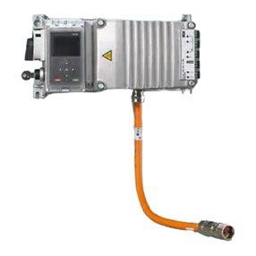
SEW-Eurodrive
SEW-Eurodrive MOVIMOT flexible MMF1 C/DBC Series operating instructions
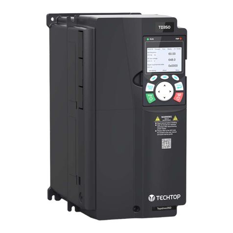
TECHTOP
TECHTOP TD350 product manual
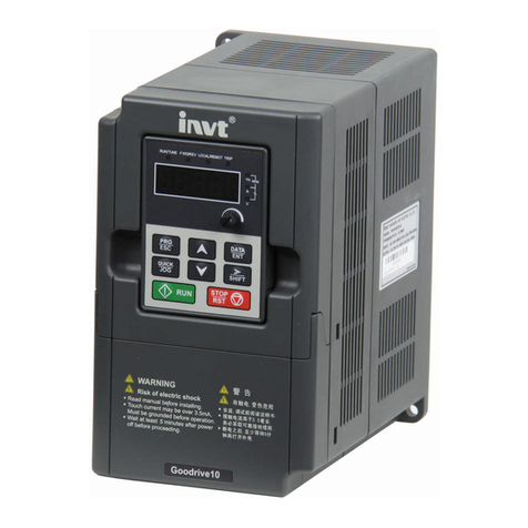
INVT
INVT 0R7G-4 Operation manual
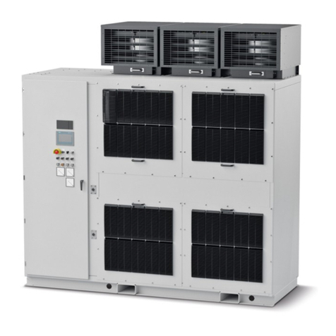
Siemens
Siemens SINAMICS PERFECT HARMONY GH180 Function manual
Pittsburgh Automotive
Pittsburgh Automotive 96718 Instructions and precautions

Applied Motion Products
Applied Motion Products STF-R Series Hardware manual

Pro-dig
Pro-dig T5K7C instruction manual

Mitsubishi Electric
Mitsubishi Electric FR-A5NPA instruction manual
Lenze
Lenze ESMD Series manual
