LOVATO ELECTRIC VLA1 series User manual

I581 GB I 05 18 31100420
1
G
B
LOVATO ELECTRIC S.P.A.
24020 GORLE (BERGAMO) ITALIA
VIA DON E. MAZZA, 12
TEL. 035 4282111
FAX (Nazionale): 035 4282200
FAX (International): +39 035 4282400
E-mail info@LovatoElectric.com
Web www.LovatoElectric.com
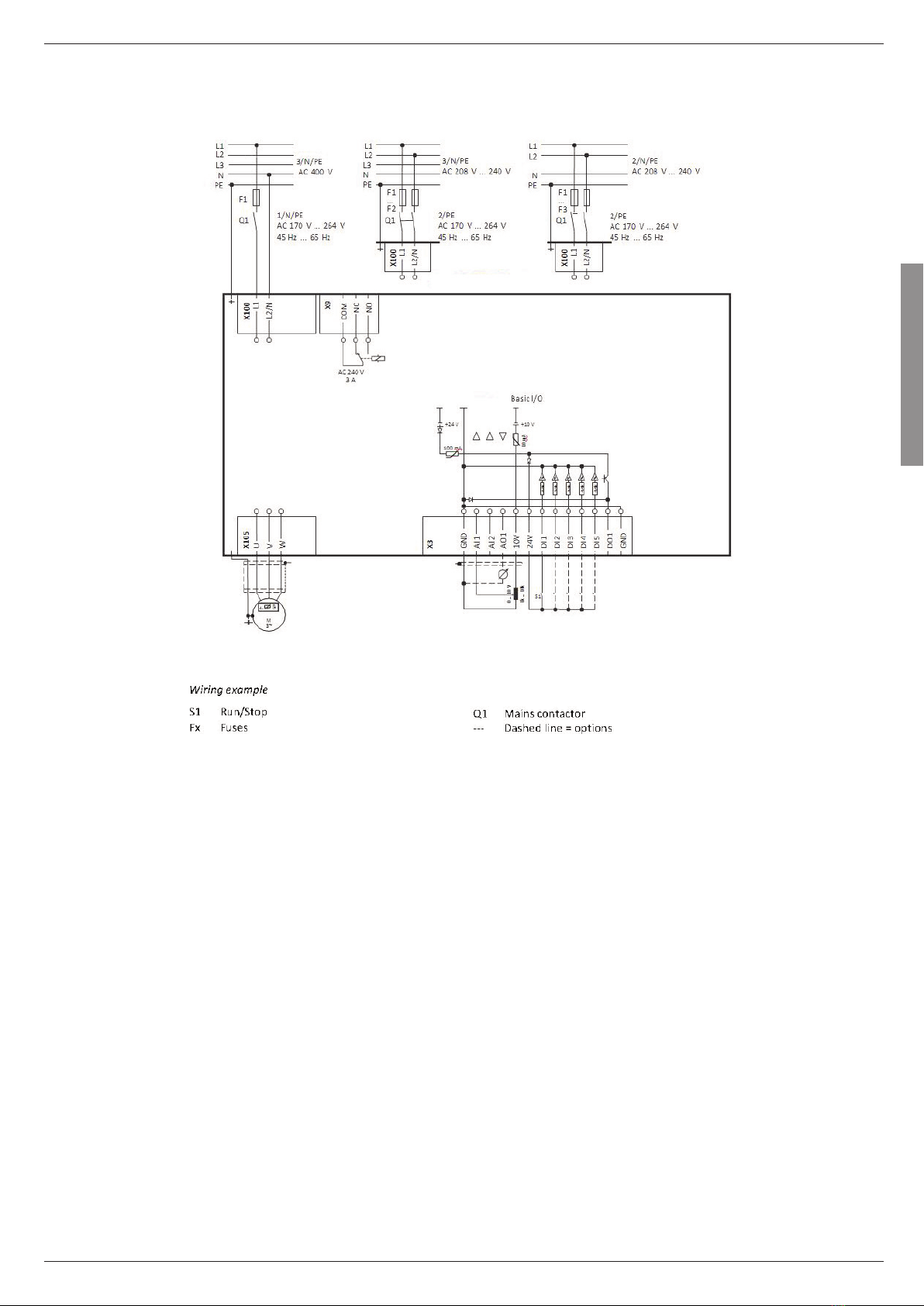
VLA1...
GB VARIABLE SPEED DRIVES
In tallation manual
I AZIONAMENTI A VELOCITÀ VARIABILE
Manuale di in tallazione
WARNING!
– Carefully read the manual before the installation or use.
– This equipment is to be installed by qualified personnel, complying to current standards, to avoid
damages or safety hazards.
– Before any maintenance operation on the device, remove all the voltages from measuring and supply inputs and short-
circuit the CT input terminals.
– The manufacturer cannot be held responsible for electrical safety in case of improper use of the equipment.
– Products illustrated herein are subject to alteration and changes without prior notice. Technical data and descriptions in
the documentation are accurate, to the best of our knowledge, but no liabilities for errors, omissions or contingencies
arising there from are accepted.
– A circuit breaker must be included in the electrical installation of the building. It must be installed close by the
equipment and within easy reach of the operator. It must be marked as the disconnecting device of the equipment:
IEC /EN 61010-1 § 6.11.3.1.
– Clean the device with a soft dry cloth; do not use abrasives, liquid detergents or solvents.
ATTENZIONE!
– Leggere attentamente il manuale prima dell’utilizzo e l’installazione.
– Questi apparecchi devono essere installati da personale qualificato, nel rispetto delle vigenti normative
impiantistiche, allo scopo di evitare danni a persone o cose.
– Prima di qualsiasi intervento sullo strumento, togliere tensione dagli ingressi di misura e di alimentazione e
cortocircuitare i trasformatori di corrente.
– Il costruttore non si assume responsabilit in merito alla sicurezza elettrica in caso di utilizzo improprio del dispositivo.
– I prodotti descritti in questo documento sono suscettibili in qualsiasi momento di evoluzioni o di modifiche. Le
descrizioni ed i dati a catalogo non possono pertanto avere alcun valore contrattuale.
– Un interruttore o disgiuntore va compreso nell’impianto elettrico dell’edificio. Esso deve trovarsi in stretta vicinanza
dell’apparecchio ed essere facilmente raggiungibile da parte dell’operatore. Deve essere marchiato come il dispositivo di
interruzione dell’apparecchio: IEC/ EN 61010-1 § 6.11.3.1.
– Pulire l’apparecchio con panno morbido, non usare prodotti abrasivi, detergenti liquidi o solventi.
ATTENTION !
– Lire attentivement le manuel avant toute utilisation et installation.
– Ces appareils doivent être installés par un personnel qualifié, conformément aux normes en vigueur en
matière d'installations, afin d'éviter de causer des dommages des personnes ou choses.
– Avant toute intervention sur l'instrument, mettre les entrées de mesure et d'alimentation hors tension et court-circuiter
les transformateurs de courant.
– Le constructeur n'assume aucune responsabilité quant la sécurité électrique en cas d'utilisation impropre du
dispositif.
– Les produits décrits dans ce document sont susceptibles d'évoluer ou de subir des modifications n'importe quel
moment. Les descriptions et caractéristiques techniques du catalogue ne peuvent donc avoir aucune valeur
contractuelle.
– Un interrupteur ou disjoncteur doit être inclus dans l'installation électrique du bâtiment. Celui-ci doit se trouver tout
près de l'appareil et l'opérateur doit pouvoir y accéder facilement. Il doit être marqué comme le dispositif d'interruption
de l'appareil : IEC/ EN 61010-1 § 6.11.3.1.
– Nettoyer l’appareil avec un chiffon doux, ne pas utiliser de produits abrasifs, détergents liquides ou solvants.
UWAGA!
– Przed uży iem i instala ją urządzenia należy uważnie prze zytać niniejszą instruk ję.
– W elu uniknię ia obrażeń osób lub uszkodzenia mienia tego typu urządzenia muszą być instalowane przez
wykwalifikowany personel, zgodnie z obowiązują ymi przepisami.
– Przed rozpo zę iem jaki hkolwiek pra na urządzeniu należy odłą zyć napię ie od wejść pomiarowy h i zasilania oraz zewrzeć
za iski przekładnika prądowego.
– Produ ent nie przyjmuje na siebie odpowiedzialnoś i za bezpie zeństwo elektry zne w przypadku niewłaś iwego użytkowania
urządzenia.
– Produkty opisane w niniejszym dokumen ie mogą być w każdej hwili udoskonalone lub zmodyfikowane. Opisy oraz dane
katalogowe nie mogą mieć w związku z tym żadnej wartoś i umownej.
– W instala ji elektry znej budynku należy uwzględnić przełą znik lub wyłą znik automaty zny. Powinien on znajdować się w
bliskim sąsiedztwie urządzenia i być łatwo osiągalny przez operatora. Musi być ozna zony jako urządzenie służą e do wyłą zania
urządzenia: IEC/ EN 61010-1 § 6.11.3.1.
– Urządzenie należy zyś ić miękką szmatką, nie stosować środkow ś ierny h, płynny h detergentow lub rozpusz zalnikow.
ACHTUNG!
– Dieses Handbuch vor Gebrauch und Installation aufmerksam lesen.
– Zur Vermeidung von Personen- und Sachschäden dürfen diese Geräte nur von qualifiziertem
Fachpersonal und unter Befolgung der einschlägigen Vorschriften installiert werden.
– Vor jedem Eingriff am Instrument die Spannungszufuhr zu den Messeingängen trennen und die Stromwandler
kurzschlieβen.
– Bei zweckwidrigem Gebrauch der Vorrichtung übernimmt der Hersteller keine Haftung für die elektrische Sicherheit.
– Die in dieser Broschüre beschriebenen Produkte können jederzeit weiterentwickelt und geändert werden. Die im Katalog
enthaltenen Beschreibungen und Daten sind daher unverbindlich und ohne Gewähr.
– In die elektrische Anlage des Gebäudes ist ein Ausschalter oder Trennschalter einzubauen. Dieser muss sich in
unmittelbarer Nähe des Geräts befinden und vom Bediener leicht zugänglich sein. Er muss als Trennvorrichtung für das
Gerät gekennzeichnet sein: IEC/ EN 61010-1 § 6.11.3.1.
– Das Gerät mit einem weichen Tuch reinigen, keine Scheuermittel, Flüssigreiniger oder Lösungsmittel verwenden.
ADVERTENCIA
– Leer atentamente el manual antes de instalar y utilizar el regulador.
– Este dispositivo debe ser instalado por personal cualificado conforme a la normativa de instalación
vigente a fin de evitar daños personales o materiales.
– Antes de realizar cualquier operación en el dispositivo, desconectar la corriente de las entradas de alimentación y
medida, y cortocircuitar los transformadores de corriente.
– El fabricante no se responsabilizará de la seguridad eléctrica en caso de que el dispositivo no se utilice de forma
adecuada.
– Los productos descritos en este documento se pueden actualizar o modificar en cualquier momento. Por consiguiente,
las descripciones y los datos técnicos aquí contenidos no tienen valor contractual.
– La instalación eléctrica del edificio debe disponer de un interruptor o disyuntor. Éste debe encontrarse cerca del
dispositivo, en un lugar al que el usuario pueda acceder con facilidad. Además, debe llevar el mismo marcado que el
interruptor del dispositivo (IEC/ EN 61010-1 § 6.11.3.1).
– Limpiar el dispositivo con un trapo suave; no utilizar productos abrasivos, detergentes líquidos ni disolventes.
ПРЕДУПРЕЖДЕНИЕ!
– Прежде чем приступать к монтажу или эксплуатации устройства, внимательно ознакомьтесь с одержанием
настоящего руководства.
– Во избежание травм или материального ущерба монтаж должен существляться только квалифицированным персоналом
в соответствии с действующими нормативами.
– Перед проведением любых работ по техническому обслуживанию устройства необходимо обесточить все измерительные
и питающие входные контакты, а также замкнуть накоротко входные контакты трансформатора тока (ТТ).
– Производитель не несет ответственность за обеспечение электробезопасности в случае ненадлежащего использования
устройства.
– Изделия, описанные в настоящем документе, в любой момент могут подвергнуться изменениям или
усовершенствованиям. Поэтому каталожные данные и описания не могут рассматриваться как действительные с точки
зрения контрактов
– Электрическая сеть здания должна быть оснащена автоматическим выключателем, который должен быть расположен
вблизи оборудования в пределах доступа оператора. Автоматический выключатель должен быть промаркирован как
отключающее устройство оборудования: IEC /EN 61010-1 § 6.11.3.1.
– Очистку устройства производить с помощью мягкой сухой ткани, без применения абразивных материалов, жидких
моющих средств или растворителей.
UPOZORNĚNÍ
– Návod se pozorně pročtěte, než začnete regulátor instalovat a používat.
– Tato zařízení smí instalovat kvalifikovaní pra ovní i v souladu s platnými předpisy a normami pro před házení
úrazů osob či poškození vě í.
– Před jakýmkoli zásahem do přístroje odpojte měři í a napáje í vstupy od napětí a zkratujte transformátory proudu.
– Výrob e nenese odpovědnost za elektri kou bezpečnost v případě nevhodného používání regulátoru.
– Výrobky popsané v tomto dokumentu mohou kdykoli projít úpravami či dalším vývojem. Popisy a údaje uvedené v katalogu nemají
proto žádnou smluvní hodnotu.
– Spínač či odpojovač je nutno zabudovat do elektri kého rozvodu v budově. Musejí být nainstalované v těsné blízkosti přístroje a
snadno dostupné pra ovníku obsluhy. Je nutno ho označit jako vypína í zařízení přístroje: IEC/ EN 61010-1 § 6.11.3.1.
– Přístroj čistěte měkkou utěrkou, nepoužívejte abrazivní produkty, tekutá čistidla či rozpouštědla.
DİKKAT!
– Montaj ve kullanımdan ön e bu el kitabını dikkatli e okuyunuz.
– Bu aparatlar kişilere veya nesnelere zarar verme ihtimaline karşı yürürlükte olan sistem kurma normlarına göre
kalifiye personel tarafından monte edilmelidirler
– Aparata ( ihaz) herhangi bir müdahalede bulunmadan ön e ölçüm girişlerindeki gerilimi kesip akım transformatörlerinede kısa
devre yaptırınız.
– Üreti i aparatın hatalı kullanımından kaynaklanan elektriksel güvenliğe ait sorumluluk kabul etmez.
– Bu dokümanda tarif edilen ürünler her an evrimlere veya değişimlere açıktır. Bu sebeple katalogdaki tarif ve değerler herhangi bir
bağlayı ı değeri haiz değildir.
– Binanın elektrik sisteminde bir anahtar veya şalter bulunmalıdır. Bu anahtar veya şalter operatörün kolaylıkla ulaşabile eği yakın
bir yerde olmalıdır. Aparatı ( ihaz) devreden çıkartma görevi yapan bu anahtar veya şalterin markası: IEC/ EN 61010-1 § 6.11.3.1.
– Aparatı ( ihaz) sıvı deterjan veya solvent kullanarak yumuşak bir bez ile siliniz aşındırı ı temizlik ürünleri kullanmayınız.
AVERTIZARE!
– Citiţi u atenţie manualul înainte de instalare sau utilizare.
– A est e hipament va fi instalat de personal alifi at, în onformitate u standardele a tuale, pentru a evita
deteriorări sau peri olele.
– Înainte de efe tuarea ori ărei operaţiuni de întreţinere asupra dispozitivului, îndepărtaţi toate tensiunile de la intrările de măsurare
şi de alimentare şi s urt ir uitaţi bornele de intrare CT.
– Produ ătorul nu poate fi onsiderat responsabil pentru siguranţa ele tri ă în az de utilizare in ore tă a e hipamentului.
– Produsele ilustrate în prezentul sunt supuse modifi ărilor şi s himbărilor fără notifi are anterioară. Datele tehni e şi des rierile din
do umentaţie sunt pre ise, în măsura unoştinţelor noastre, dar nu se a eptă ni io răspundere pentru erorile, omiterile sau
evenimentele neprevăzute are apar a urmare a a estora.
– Trebuie in lus un disjun tor în instalaţia ele tri ă a lădirii. A esta trebuie instalat aproape de e hipament şi într-o zonă uşor
a esibilă operatorului. A esta trebuie mar at a fiind dispozitivul de de one tare al e hipamentului: IEC/EN 61010-1 § 6.11.3.1.
– Curăţaţi instrumentul u un material textil moale şi us at; nu utilizaţi substanţe abrazive, detergenţi li hizi sau solvenţi.

I581 GB I 05 18 31100420
2
G
B
CONTENTS
1 Safety nformat on ................................................................................................................................................................................................. 3
1.1 Basic safety measures .................................................................................................................................................................................................................................................. 3
1.2 Residual hazards .................................................................................................................................................................................................................................................................... 3
1.3 Application as directed ................................................................................................................................................................................................................................................. 3
2 Product descr pt on ............................................................................................................................................................................................... 4
3 Mount ng ............................................................................................................................................................................................................ 5
3.1 Important notes ............................................................................................................................................................................................................................................................ 5
3.2 Mechanical installation ................................................................................................................................................................................................................................................. 5
3.3 Electrical installation ..................................................................................................................................................................................................................................................... 8
3.3.1 1-phase mains connection 230/240 V ..................................................................................................................................................................................................... 8
3.3.1.1 Fusing and terminal data ............................................................................................................................................................................................................ 9
3.3.2 Connection to the IT system .................................................................................................................................................................................................................... 10
4 Comm ss on ng .................................................................................................................................................................................................... 11
4.1 Important notes ............................................................................................................................................................................................................................................................ 11
4.2 Before initial switch-on ................................................................................................................................................................................................................................................. 11
4.3 Initial switch-on / functional test with terminal control ................................................................................................................................................................................................. 11
5 Techn cal data ..................................................................................................................................................................................................... 13
5.1 Standards and operating conditions ............................................................................................................................................................................................................................. 13
5.2 Technical data ............................................................................................................................................................................................................................................................... 14

I581 GB I 05 18 31100420
3
G
B
1 SAFETY INFORMATION
1.1 Basic safety measures
Disregarding the following basic safety measures may lead to severe personal injury and damage to material assets!
The product
– must only be used as directed.
– must never be commissioned if they display signs of damage.
– must never be technically modified.
– must never be commissioned if they are not fully mounted.
– must never be operated without required covers.
Connect/disconnect all pluggable terminals only in deenergised condition. Only remove the product from the installation in the deenergised state.
Insulation resistance tests between 24V control potential and PE: According to EN 61800−5−1, the maximum test voltage must not exceed 110 V DC.
Observe all specifications of the corresponding documentation supplied. This is the precondition for safe and trouble-free operation and for obtaining the product features specified.
The procedural notes and circuit details described in this document are only proposals. It is up to the user to check whether they can be adapted to the particular applications. LOVATO Electric does
not take any responsibility for the suitability of the procedures and circuit proposals described.
The product must only be used by qualified personnel. IEC 60364 define the skills of these persons:
– They are familiar with installing, mounting, commissioning, and operating the product.
– They have the corresponding qualifications for their work.
– They know and can apply all regulations for the prevention of accidents, directives, and laws applicable at the place of use.
Observe the specific notes in the other chapters!
1.2 Residual hazards
The user must take the residual hazards mentioned into consideration in the risk assessment for his/her machine/system.
If the above is disregarded, this can lead to severe injuries to persons and damage to material assets!
PRODUCT
Observe the warning labels on the product!
ICON DESCRIPTION
Electrostat c sens t ve dev ces
Before working on the drive, the staff must ensure to be free of electrostatic charge!
Dangerous electr cal voltage
Before working on the drive, check whether all power connections are dead! After mains OFF, power connections X100 and X105 carry a dangerous electrical
voltage for the time specified on the drive!
H gh leakage current
Carry out fixed installation and PE connection in compliance with EN 61800-5-1 or EN 60204-1!
Hot surface
Use personal protective equipment or wait until devices have cooled down!
MOTOR
If there is a short circuit of two power transistors, a residual movement of up to 180°/number of pole pairs can occur at the motor! (For 4-pole motor: residual movement max. 180°/2 = 90°).
This residual movement must be taken into consideration by the user for his/her risk assessment.
1.3 Application as directed
– The product must only be operated under the operating conditions prescribed in this documentation.
– The product meets the protection requirements of 2014/35/EU: Low-Voltage Directive.
– The product is not a machine in terms of 2006/42/EC: Machinery Directive.
– Commissioning or starting the operation as directed of a machine with the product is not permitted until it has been ensured that the machine meets the regulations of the EC Directive
2006/42/EC: Machinery Directive; observe EN 60204−1.
– Commissioning or starting the operation as directed is only allowed when there is compliance with the EMC Directive 2014/30/EU.
– The harmonised standard EN 61800−5−1 is used for the drives.
– The product is not a household appliance, but is only designed as component for commercial or profes- sional use in terms of EN 61000−3−2.
– In accordance with EN 61800−3, the product can be used in drive systems that have to comply with the categories given in the technical data.
In residential areas, the product may cause EMC interferences. The operator is responsible for taking interference suppression measures.

I581 GB I 05 18 31100420
4
G
B
2 PRODUCT DESCRIPTION

I581 GB I 05 18 31100420
5
G
B
3 MOUNTING
3.1 IMPORTANT NOTES
DANGER!
Dangerous electrical voltage
Possible consequence: death or severe injuries
▶All work on the drive must only be carried out in the de-energised state.
▶After switching off the mains voltage, wait for at least 3 minutes before you start working.
3.2 MECHANICAL INSTALLATION
VLA1 02 A240 – VLA1 04 A240
All dimensions in mm

I581 GB I 05 18 31100420
6
G
B
VLA1 07 A240
All dimensions in mm

I581 GB I 05 18 31100420
7
G
B
VLA1 15 A240 – VLA1 22 A240
All dimensions in mm

I581 GB I 05 18 31100420
8
G
B
3.3 ELECTRICAL INSTALLATION
3.3.1 1-PHASE MAINS CONNECTION 230/240 V

I581 GB I 05 18 31100420
9
G
B
3.3.1.1 FUSING AND TERMINAL DATA
Power kW 0.25 0.4 0.75 1.5 2.2
Cable installation in compliance with EN 60204-1
Laying system B2
Operation without mains choke
Fuse
Characteristic gG/gL or gRL
Max. rated current A 10 10 16 25 25
Circuit breaker
Characteristic B
Max. rated current A 10 10 16 25 25
Operation with mains choke
Fuse
Characteristic gG/gL or gRL
Max. rated current A 10 10 16 25 25
Circuit breaker
Characteristic B
Max. rated current A 10 10 16 25 25
Earth-leakage circuit breaker ≥ 30 mA, type A or B
Mains connection
Connection X100
Connection type Screw terminal
Min. cable cross-section mm² 1
Max. cable cross-section mm² 2.5 6
Stripping length mm 8
Tightening torque Nm 0.5 0.7
Required tool 0.5 x 3.0 0.6 x 3.5
Motor connection
Connection X105
Connection type Screw terminal
Min. cable cross-section mm² 1
Max. cable cross-section mm² 2.5
Stripping length mm 8
Tightening torque Nm 0.5
Required tool 0.5 x 3.0
PE connection
Connection PE
Connection type PE screw
Min. cable cross-section mm² 1
Max. cable cross-section mm² 6
Stripping length mm 10
Tightening torque Nm 1.2
Required tool 0.8 x 5.5

I581 GB I 05 18 31100420
10
3.3.2 CONNECTION TO THE IT SYSTEM
NOTICE!
Internal components have earth/ground potential if the IT screws are not removed. Consequence: the monitoring functions of the IT system respond.
Before connection to an IT system be absolutely sure to remove the IT screws.
G
B
(from size 0.75kW)

I581 GB I 05 18 31100420
11
G
B
4 COMMISSIONING
4.1 IMPORTANT NOTES
Incorrect settings during commissioning may cause unexpected and dangerous motor and system movements.
Possible consequence: death, severe injuries or damage to property
– Clear hazardous area.
– Observe safety instructions and safety clearances.
4.2 BEFORE INITIAL SWITCH-ON
Prevent injury to persons and damage to property. Check the following before switching on the mains voltage:
– Is the wiring complete and correct?
– Are there no short circuits and earth faults?
– Is the motor circuit configuration (star/delta) adapted to the output voltage of the drive?
– Is the motor connected in-phase (direction of rotation)?
– Does the "emergency stop" function of the entire plant operate correctly?
4.3 INITIAL SWITCH-ON / FUNCTIONAL TEST WITH TERMINAL CONTROL
Target: achieve rotation of the motor connected to the drive as quickly as possible. Requirements:
– The connected motor matches the drive in terms of power.
– The parameter settings comply with the delivery status (LOVATO setting).
1. Preparation:
1. Wiring of power terminals. (Chapter 3.3 Electrical installation)
2. Wire digital inputs X3/DI1 (start/stop), X3/DI3 (reversal of rotation direction), and X3/DI4 (preset frequency setpoint 20 Hz).
3. Do not connect terminal X3/AI1 (analog setpoint selection) or connect it to GND.
2. Switch on mains and check readiness for operation:
1. Switch on mains voltage.
2. Observe LED status displays "RDY" and "ERR" on the front of the drive:
a) If the blue "RDY" LED is blinking and the red "ERR" LED is off, the drive is ready for operation. The controller is inhibited.
You can now start the drive.
b) If the red "ERR" LED is lit permanently, a fault is pending.
Eliminate the fault before you carry on with the functional test.
X3
4
LED STATUS DISPLAYS
"RDY" LED (blue) "ERR" LED (red) Status/meaning
off off No supply voltage.
blinking (2 Hz) off Drive inhibited.
lit every 1.5 s for a short time Drive inhibited, no DC-bus voltage.
blinking fast (4 Hz) Drive inhibited, warning active.
on Drive inhibited, fault active.
on off Drive enabled. The drive rotates according to the setpoint specified.
blinking fast (4 Hz) Drive enabled, warning active.
blinking (1 Hz) Drive enabled, quick stop as response to a fault active.

I581 GB I 05 18 31100420
12
G
B
Carrying out the functional test
1. Start drive:
1. Enable drive: X3/DI1 = HIGH.
2. Activate preset setpoint 1 (20 Hz) as speed setpoint: X3/DI4 = HIGH.
The drive rotates with 20 Hz.
3. Optional: activate the function for the reversal of rotation direction.
a) X3/DI3 = HIGH.
The drive rotates with 20 Hz in the opposite direction.
b) Deactivate the function for the reversal of rotation direction again: X3/DI3 = LOW.
Speed characteristic (example)
2. Stop drive:
1. Deactivate preset setpoint 1 again: X3/DI4 = LOW.
2. Stop drive again: X3/DI1 = LOW.
The functional test is completed.
Drive follows the frequency setpoint

I581 GB I 05 18 31100420
13
G
B
5 TECHNICAL DATA
5.1 STANDARDS AND OPERATING CONDITIONS
Conformities
CE 2014/35/EU Low-Voltage Directive
2014/30/EU EMC Directive (reference: CE-typical drive system)
EAC TR TC 004/2011 Eurasian conformity: safety of low voltage equipment
TP TC 020/2011 Eurasian conformity: electromagnetic compatibility of technical means
RoHS 2 2011/65/EU Restrictions for the use of specific hazardous materials in electric and electronic devices
Approvals
UL UL 61800-5-1 for USA and Canada (requirements of the CSA 22.2 No. 274)
Energy efficiency
Class IE2 EN 50598-2 Reference: LOVATO setting (switching frequency 8 kHz variable)
Degree of protection
IP20 EN 60529
Type 1 NEMA 250 Protection against contact
Insulation resistance
Overvoltage category III EN 61800-5-1 0 … 2000 m a.m.s.l.
Overvoltage category II above 2000 m a.m.s.l.
Control circuit isolation
Safe mains isolation by double/ reinforced EN 61800-5-1
insulation
Protective measures against
Short circuit
Earth fault Earth fault strength depends on the operating status
Overvoltage
Motor stalling
Motor overtemperature I²xt monitoring
Leakage current
> 3.5 mA AC, > 10 mA DC EN 61800-5-1 Observe regulations and safety instructions!
Mains switching
3-time mains switching in 1 min Cyclic, without any restrictions
Starting current
≤ 3 x rated mains current
Mains systems
TT Voltage to earth/ground: max. 300 V
TN
IT Apply the measures described for IT systems!
Operation on public supply systems
Implement measures to limit the radio The machine or plant manufacturer is responsible for compliance with the requirements for the
interference to be expected: machine/ plant!
< 1 kW: with mains choke EN 61000-3-2
> 1 kW at mains current ≤ 16 A:
without additional measures
Mains current > 16 A: with mains choke or EN 61000-3-12 RSCE: short-circuit power ratio at the connection point of the machine/plant to the public network.
mains filter, with dimensioning for rated
power. Rsce ≥ 120 is to be met.
Requirements to the shielded motor cable
Capacitance per unit length
C-core-core/C-core-shield < 75/150 pF/m ≤ 2.5 mm² / AWG 14
C-core-core/C-core-shield < 150/300 pF/m ≥ 4 mm² / AWG 12
Electric strength
Uo/U = 0.6/1.0 kV U = r.m.s. value external conductor/external conductor
Uo = r.m.s. value external conductor to PE
U ≥ 600 V UL U = r.m.s. value external conductor/external conductor
Climate
1K3 (-25 ... +60 °C) EN 60721-3-1 Storage
2K3 (-25 ... +70 °C) EN 60721-3-2 Transport
3K3 (-10 ... +55 °C) EN 60721-3-3 Operation
Operation at a switching frequency of 8 or 16 kHz: above +40°C, reduce rated output current by 2.5 %/°C

I581 GB I 05 18 31100420
14
G
B
Site altitude
0 … 1000 m a.m.s.l.
1000 … 4000 m a.m.s.l. Reduce rated output current by 5 %/1000 m
Pollution
Degree of pollution 2 EN 61800-5-1
Vibration resistance
Transport
2M2 (sine, shock) EN 60721-3-2
Operation
Amplitude 1 mm Germanischer Lloyd 5 ... 13.2 Hz
Acceleration resistant up to 0.7 g 13.2 ... 100 Hz
Amplitude 0.075 mm EN 61800-5-1 10 ... 57 Hz
Acceleration resistant up to 1 g 57 ... 150 Hz
Noise emission
Category C2 EN 61800-3 Type-dependent, for motor cable lengths see rated data
Noise immunity
Meets requirement in compliance with EN 61800-3
5.2 TECHNICAL DATA
The output currents apply to these operating conditions:
– At a switching frequency of 2 kHz or 4 kHz: Max. ambient temperature 45°C.
– At a switching frequency of 8 kHz or 16 kHz: Max. ambient temperature 40 °C.
Power kW 0.25 0.4 0.75 1.5 2.2
Mains voltage range 1/N/PE AC 170 V ... 264 V, 45 Hz ... 65 Hz
Rated mains current
without mains choke A 4 5.7 10 16.7 22.5
with mains choke A 3.6 4.8 8.8 13.9 16.9
Output current
2 kHz A - - 4.2 7 9.6
4 kHz A 1.7 2.4 4.2 7 9.6
8 kHz A 1.7 2.4 4.2 7 9.6
16 kHz A 1.1 1.6 2.8 4.7 6.4
Power loss W 15 20 33 50 70
Overcurrent cycle 180 s
Max. output current A 2.55 3.6 6.3 10.5 14.4
Overload time s 60 60 60 60 60
Recovery time s 120 120 120 120 120
Max. output current during the recovery time A 1.28 1.8 3.15 5.25 7.2
Overcurrent cycle 15 s
Max. output current A 3.4 4.8 8.4 14 19.2
Overload time s 3 3 3 3 3
Recovery time s 12 12 12 12 12
Max. output current during the recovery time A 1.28 1.8 3.15 5.25 7.2
Motor cable length
shielded, without EMC m 50
C2 residential area / industrial premises m 520
Weight kg 0.75 0.95 1.35

I581 GB I 05 18 31100420
15
I
CONTENUTI
1 Informaz on sulla s curezza ..................................................................................................................................................................................... 16
1.1 Misure base di sicurezza ............................................................................................................................................................................................................................................... 16
1.2 Pericoli ......................................................................................................................................................................................................................................................................... 16
1.3 Destinazione d’uso ....................................................................................................................................................................................................................................................... 16
2 Descr z one prodotto .............................................................................................................................................................................................. 17
3 Montagg o .......................................................................................................................................................................................................... 18
3.1 Note importanti ............................................................................................................................................................................................................................................................. 18
3.2 Installazione meccanica ................................................................................................................................................................................................................................................ 18
3.3 Installazione elettrica ..................................................................................................................................................................................................................................................... 21
3.3.1 Connessione a rete monofase 230/240V ................................................................................................................................................................................................. 21
3.3.1.1 Fusibili e terminali ...................................................................................................................................................................................................................... 22
3.3.2 Connessione a sistema IT ........................................................................................................................................................................................................................ 23
4 Pr mo avv amento ................................................................................................................................................................................................. 24
4.1 Note importanti ............................................................................................................................................................................................................................................................ 24
4.2 Prima di dare tensione / start ....................................................................................................................................................................................................................................... 24
4.3 Accensione iniziale / test funzionali ............................................................................................................................................................................................................................... 24
5 Dat tecn c ......................................................................................................................................................................................................... 26
5.1 Norme e condizioni di funzionamento .......................................................................................................................................................................................................................... 26
5.2 Dati tecnici..................................................................................................................................................................................................................................................................... 27

I581 GB I 05 18 31100420
16
I
1 INFORMAZIONI SULLA SICUREZZA
1.1 Misure base di sicurezza
La mancata osservanza delle seguenti misure base di sicurezza può comportare gravi lesioni alle persone e danni materiali!
Il prodotto:
– deve essere utilizzato solo come da prescrizioni del seguente documento.
– non deve mai essere messo in servizio se presenta segni di danneggiamento.
– non deve essere mai modificato tecnicamente.
– non deve essere mai messo in servizio se non è completamente montato.
– non deve mai essere utilizzato senza le necessarie protezioni di sicurezza.
Collegare/scollegare le connessioni rimovibili solo con azionamento disalimentato.
Rimuovere il prodotto dall’installazione solo in assenza di tensione.
Prove di resistenza d’isolamento tra il potenziale di controllo 24V e PE: Secondo EN 61800−5−1, la tensione di prova massima non deve superare 110 V DC.
Per un funzionamento sicuro e senza problemi che risponda alle caratteristiche del prodotto osservare tutte le indicazioni specificate sulla documentazione fornita.
Le note procedurali e i dettagli sul circuito descritti in questo documento sono solo delle proposte. È compito dell’utilizzatore verificare se possono essere adattati alle particolari applicazioni.
LOVATO Electric non si assume alcuna responsabilit per l’idoneit delle procedure e proposte di circuito descritte.
Il prodotto deve essere utilizzato esclusivamente da personale qualificato. Lo standard IEC 60364 definisce le competenze di queste persone:
– hanno familiarit con l’installazione, montaggio, messa in servizio e utilizzo del prodotto.
– Hanno le qualifiche necessarie per la propria attivit .
– Conoscono e possono applicare tutte le regole per la prevenzione di incidenti, direttive e leggi applicabili sul luogo di utilizzo.
Osservare le note specifiche negli altri capitoli!
1.2 PERICOLI
L'utente deve prendere in considerazione i rischi residui citati nella valutazione del rischio per il suo impianto o la sua macchina. Se quanto sopra viene ignorato, si possono generare gravi lesioni
alle persone e danni ai materiali installati!
PRODOTTO
Prestare attenzione alle etichette di Warning apposte sui prodotti!
ICONA DESCRIZIONE
D spos t v sens b l a scar che elettrostat che:
Prima di agire sull’azionamento, l’operatore deve essere certo di non essere portatore di cariche elettrostatiche pericolose!
Tens one elettr ca per colosa
Dopo la disinserzione della rete le connessioni di potenza X100 e X105 presentano una tensione elettrica pericolosa per il tempo specificato sull’azionamento.
Alte corrent d d spers one:
Accertarsi che l’installazione e la connessione PE sia realizzata in conformit a EN 61800−5−1 o EN 60204−1!
Superf c calde:
Utilizzare opportune equipaggiamenti di protezione o attendere il raffreddamento del prodotto!
MOTORE
Se c’è un cortocircuito di due transistor di potenza, si può avere una rotazione residua dell’albero motore pari a 180°/numero di coppie polari! (Per un motore a 4 poli, la rotazione residua è max.
180°/2 = 90°). Questa rotazione residua deve essere tenuta in considerazione nella valutazione rischi dell’installazione.
1.3 Destinazione d’uso
– Il prodotto deve essere utilizzato come da prescrizioni del presente documento.
– Il prodotto rispetta I requisiti di protezione 2014/35/EU: Direttiva Bassa tensione.
– Il prodotto non è una Macchina nei termini indicati da 2006/42/EC: Direttiva Macchine.
– La messa in servizio o l’avviamento di una macchina non è consentita finché non è stato accertato che la macchina è conforme alle disposizioni della Direttiva EC 2006/42/EC: Direttiva Macchine;
osservare EN 60204−1.
– La messa in servizio o l’avvio delle operazioni è permesso solo se è si è in conformit alla Direttiva EMC 2014/30/EU.
– Lo standard armonizzato EN 61800−5−1 è utilizzato per gli azionamenti a velocit variabile.
– Il prodotto non è un elettrodomestico, ma è progettato esclusivamente come componente per uso commerciale o professionale secondo lo standard EN 61000−3−2.
– In conformit con EN 61800−3, il prodotto può essere utilizzato in sistemi di azionamento che rispettano le categorie indicate nei dati tecnici.
Nelle aree residenziali, il prodotto può causare interferenze EMC. L’operatore è responsabile dell’adozione di misure per la soppressione delle interferenze.

I581 GB I 05 18 31100420
17
I
2 DESCRIZIONE PRODOTTO

I581 GB I 05 18 31100420
18
I
3 MONTAGGIO
3.1 NOTE IMPORTANTI
PERICOLO!
Tensione elettrica pericolosa
Possibili conseguenze: morte o gravi lesioni
▶ tutte le operazioni sull’azionamento devono essere eseguite in assenza di tensione.
▶dopo avere rimosso la tensione di alimentazione, attendere almeno 3 minuti prima di ricominciare a lavorare.
3.2 INSTALLAZIONE MECCANICA
VLA1 02 A240 – VLA1 04 A240
Dimensioni in mm

I581 GB I 05 18 31100420
19
I
VLA1 07 A240
Dimensioni in mm

I581 GB I 05 18 31100420
20
I
VLA1 15 A240 – VLA1 22 A240
Dimensioni in mm
Other manuals for VLA1 series
1
This manual suits for next models
10
Table of contents
Languages:
Other LOVATO ELECTRIC DC Drive manuals
Popular DC Drive manuals by other brands

GFA
GFA 10003166 10011 installation instructions

Claus
Claus C20/30 Safety instructions

Unitek
Unitek Classic Q3 15-150A 4 Quadrant manual

Danfoss
Danfoss VLT 8000 AQUA series operating instructions

Fcontrol
Fcontrol FXDM series quick start guide

Aumuller
Aumuller KS2 Twin Assembly and commissioning instructions