AC90 TENSION CONTROL FREQUENCY INVERTER MANUAL BASIC OPERATION AND TRIAL RUN
2
Operation requirement
Only Professonal trained person are allowed to operate the equipment such as installation, wiring, running, maintain
and etc. “Professonal trained person”in this manual means the workers on this product must experience professional
skill train, must be familiar with installation, wiring, running and maintain and can rightly deal with emergency cases in
use.
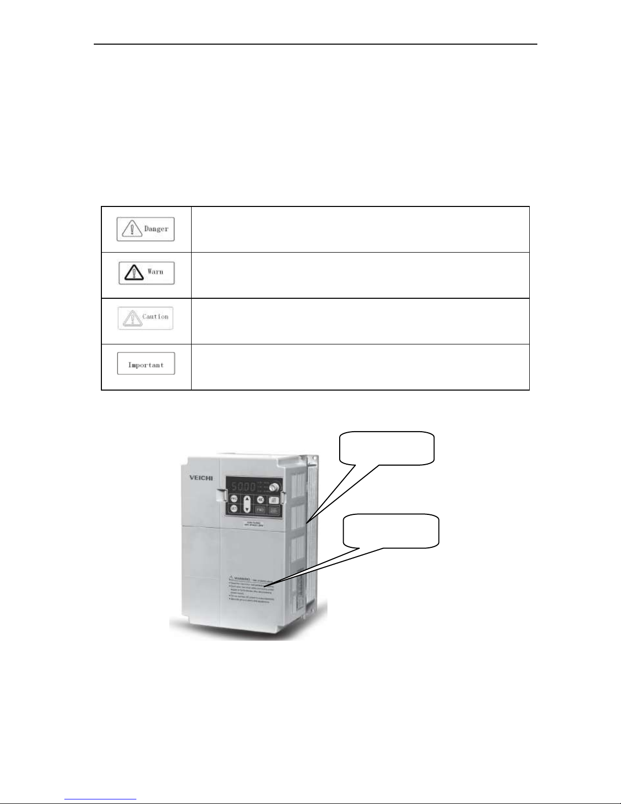
Safety guidance
Safety regulations and warning signs come for your security. They are measures to prevent the operator and machine
system from damage. Pls carefylly read this manual before using and strictly observe the refulations and warning signs
while operating. Safety regulations and warning signs are classified into: routine regulation, transport and store
regulation, installation and wiring regulation, running regulation, maintenance regulation, dismantlement and disposal
regulation.
●Routine regulation
●This product carries dangerous voltage and controls driver machine with potential danger. If
you don’t abide by the regulations or requirements in this manual, there is danger of body
injury even death and machine system damage.
●Only qualified personnels are allowed to operate the equipment.this product. Before using, the
operator must be familiar with all safety specifications and operation regulatons in this manual.
Safe and stable work of the product is based on right operation and maintenance.
●Do not wire while the power is conneted. Otherwise, there is danger of death for electric
shock. Before wiring, inspection, maintenance, please cut power supply of all related
equipments and ensure mains DC voltage in safe range. And please operate it after 5 mins.
●Away from children and public.
● Only used in application fields as maker stated. No use in equipments related to special fields
such as emergency, succor, ship, medical treatment, avigation, nuclear and etc.
●Unauthorized alteration or use of accessories which are not sold or recommended by the
maker may cause faults.
●Please make sure this manual is in the final user’hand before using.
●Before installation and debugging pls carefully read and totally understand these safety
regulation and warning signs.
●Transport and store regulation
●Correct transport, store, installation and careful operation an maintenance are important for
inverter safe operation.
● In transport and store process, make sure the inverter is free from impact and vibration. It
must be stored where is dry without corrosive air and conductive dust, and the temperature
must be lower than 60℃.
● Installation and wiring regulation
● Only professional trained person can operate it.
● Power wire, motor wire and control wire should be all connected firmly. Earth must be reliable
and earth resistance must be lower than 10Ω.
● Before opening the inverter, please disconnect all related equipment power supply and make
sure the mains DC voltage is in safe range and operate after 5mins.
● Human body electrostatic will damage inner sensitive components seriously. Before
operation, please follow ESD measures. Otherwise, there is danger of iverter damage.
● Inverter output voltage is pulse wave. If components such as capacitor which improves power
factor and pressure-sensitive resistance for anti-thunder and so on are installed at the output