manuals.online logo
Brands
  1. Home
  2. •
  3. Brands
  4. •
  5. Festo
  6. •
  7. DC Drive
  8. •
  9. Festo DFPD-HD-RD Series Parts list manual

Festo DFPD-HD-RD Series Parts list manual

Translation of the original instructions
1 About this document
This document describes the use of the above-mentioned product. Certain
aspects of use in connection with a hydraulic unit or handwheel control are
described in other documents and must be observed.
1.1 Further applicable documents
User documentation
Name, type Table of contents
Operating instructions for DFPD-HD-...-HW Design, commissioning and operation of the
hydraulic unit
Operating instructions for DFPD-HD-...-MW Design, commissioning and operation of the
handwheel control
Tab. 1
All available documents for the product èwww.festo.com/pk.
2 Safety
2.1 General safety instructions
– Only use the product in original status without unauthorised modifications.
– Only use the product if it is in perfect technical condition.
– Observe the specifications on the product labelling.
– Observe labelling on the product.
– Prior to mounting, installation and maintenance work: Switch off compressed
air supply and secure it from being switched back on.
– Exhaust drive prior to assembly, installation and dismounting.
2.1.1 Operating medium
– Only use compressed air in accordance with the specifications
è 14 Technical data.
– Use only unlubricated compressed air under normal conditions. Once the
product has been used with lubricated compressed air, it must continue to be
operated with lubricated compressed air only.
2.1.2 Return to Festo
Hazardous substances can endanger the health and safety of personnel and
cause damage to the environment. To prevent hazards, the product should only
be returned upon explicit request by Festo.
– Consult your regional Festo contact.
– Complete the declaration of contamination and attach it to the outside of the
packaging.
– Comply with all legal requirements for the handling of hazardous substances
and the transport of dangerous goods.
2.2 Intended use
The semi-rotary drive DFPD-HR is intended to actuate process valves, such as ball
valves and butterfly valves, with a rotation angle from 0° (valve closed) to 90°.
The semi-rotary drive is suitable for control of media-flow process valves in fluid
engineering systems.
NOTICE!
The operating torque of the drive must not be greater than the maximum permiss-
ible torque listed in ISO5211 in relation to the size of the mounting flange and of
the coupling.
2.3 Training of skilled personnel
Installation, commissioning, maintenance and disassembly should only be con-
ducted by qualified personnel.
3 Further information
– Accessoriesèwww.festo.com/catalogue.
– Documents and literatureèwww.festo.com/sp.
4 Service
Contact your regional Festo contact person if you have technical questions
èwww.festo.com.
5 Product overview
5.1 Design
The product labelling is located on the gear unit.
18 mounting threads according to
ISO5211
2Keyway
3Pneumatic cylinder
44 mounting threads – e.g. for
sensor box
5Transmission shaft (internal) –
delivery "Valve open"
6Adjustable stop for end position
adjustment
7Transport lug
8Gear unit
9Mechanical position indication
10 Air connection (4)
11 Air connection (2)
Fig. 1
5.2 Function
Fig. 2
The DFPD-HD-...-RD is a double-acting semi-rotary drive. The piston is moved by
pressurizing and exhausting the pneumatic cylinder.
The linear motion of the piston is transformed using a Scotch yoke system into a
swivel motion of the transmission shaft. The connected process valve records the
reaction torque of the semi-rotary drive.
Fig. 3
6 Transport and storage
WARNING!
Danger of crushing.
Body parts can be crushed if the product falls.
• Use appropriate load handling equipment.
• Lift the semi-rotary drive using the transport lugs.
• Before transporting: detach the semi-rotary drive from the process valve.
NOTICE!
For variants with a hydraulic unit (DFPD-HD-...-HW): environmental damage due to
escaping oil.
• Store the product horizontally and avoid inclines.
8087991
Semi-rotary drive
DFPD-HD-...-RD
8087991
2018-03a
[8087993]
Instructions|Operating
Festo AG & Co. KG
Ruiter Straße 82
73734 Esslingen
Germany
+49 711 347-0
www.festo.com
– When dispatching used products: Comply with all legal requirements for the
handling of hazardous substances and the transport of dangerous goods. For
return to Festo è 2.1 General safety instructions.
– Store the product in a cool, dry, UV-protected and corrosion-protected envir-
onment. Ensure that storage times are kept to a minimum.
– In case of long-term storage: regularly check the function of the semi-rotary
drive.
– Observe environmental and storage conditions è 14 Technical data.
– To prevent contamination, close any pneumatic connections.
– Protect the coupling parts with grease or protective oil.
– To prevent damage to the coupling flange, store the semi-rotary drive on a
level wooden pallet.
7 Assembly and installation
NOTICE!
Semi-rotary drives of the series DFPD-HD are intended for installation parallel to
the line axis.
• If another installation position is necessary, consult your regional Festo con-
tact èwww.festo.com.
NOTICE!
Semi-rotary drives with a hydraulic manual override are designed for a horizontal
installation position only. In this position, the pump and reservoir are mounted
towards the top of the hydraulic cylinder.
7.1 Assembly
1. Clean the coupling flange.
2. Adjust the valve position according to the semi-rotary drive settings.
3. Lubricate the valve stem.
4. Place the semi-rotary drive on the control shaft of the process valve.
5. Mount the semi-rotary drive on the connecting flange of the process valve
using 8 threaded pins.
6. Tighten the nuts of the threaded pin crosswise.
Tightening torque è Tab. 2
Flange type F25 F30 F35
Tightening torque [Nm] 160 320 1100
Tab. 2
7.2 Pneumatic installation
• Observe the operating instructions of the process valve.
• Test the correct function of the pneumatic control.
Connection Effect
2 Air supply; always connected
4 Return stroke
Tab. 3
8 Commissioning
8.1 Requirements
– The drive is fully mounted and connected.
8.2 Commissioning the semi-rotary drive
1. Check operating conditions and limit values è 14 Technical data.
2. Switch on the compressed air supply.
3. Check the semi-rotary drive for leakage.
4. First check the direction of rotation of the semi-rotary drive and reaction of
the process valve at a low travel speed.
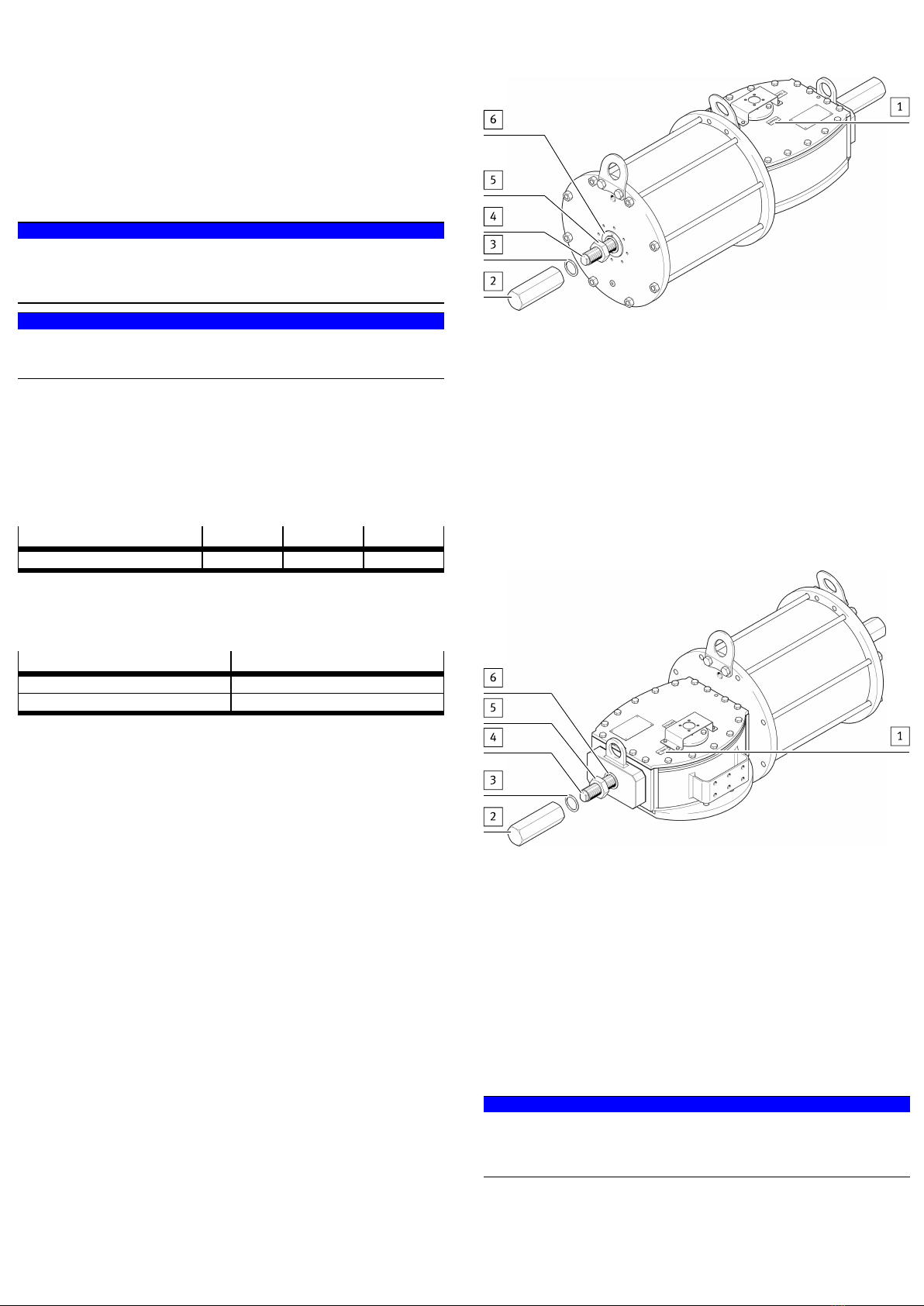
8.3 Adjusting the end position – “Valve closed” position
The “Valve closed” position is set using the adjusting screw on the end flange of
the pneumatic cylinder.
Fig. 4
1. Set the semi-rotary drive to the “Valve closed” position1.
2. Switch off the compressed air supply.
3. Remove the cover of the stop bolt 2and sealing disc3.
4. Loosen the stop nut 5together with the sealing disc6.
5. To reduce the rotation angle, screw in the stop adjusting screw4.
To increase the rotation angle, unscrew the stop adjusting screw4.
6. Tighten the stop nut5. Make sure that the sealing disc6 is centred on the
stop nut and lies in the recess of the flange.
7. Switch on the compressed air supply.
8. To check the adjustment, run through a complete cycle.
9. Put the cover of the stop bolt2 and sealing disc3 into place again.
8.4 Adjusting the end position – “Valve open” position
The “Valve open” position is set using the adjusting screw on the end flange of
the gear unit.
Fig. 5
1. Set the semi-rotary drive to the “Valve open” position1.
2. Switch off the compressed air supply.
3. Remove the cover of the stop bolt 2and sealing disc3.
4. Loosen the stop nut 5together with the sealing disc6.
5. To reduce the rotation angle, screw in the stop adjusting screw4.
To increase the rotation angle, unscrew the stop adjusting screw4.
6. Tighten the stop nut5. Make sure that the sealing disc6 is centred on the
stop nut and lies in the recess of the flange.
7. Switch on the compressed air supply.
8. To check the adjustment, run through a complete cycle.
9. Put the cover of the stop bolt2 and sealing disc3 into place again.
9 Operation
• Comply with operating conditions.
• Observe the permitted limit values.
NOTICE!
For continuous operation under extreme conditions: Use lubricated compressed
air. The oil must be chemically inert and must not carbonise. Once the product has
been used with lubricated compressed air, it must continue to be operated with
lubricated compressed air only.
10 Maintenance
When used as intended, the product is maintenance-free.
Festo recommends the following periodic inspections:
Interval Test
Annually Correct function of the semi-rotary drive by
repeatedly opening and closing the valve fully
(rotation angle = 90°)
Every six months Visual inspection (during operation)
Quarterly Correct function of the semi-rotary drive during
operation
Tab. 4
11 Malfunctions
• In case of malfunctions, consult your regional Festo contact.
12 Dismounting
WARNING!
Danger of crushing.
Body parts can be crushed if the product falls.
• Use appropriate load handling equipment.
• Lift the semi-rotary drive using the transport lugs.
• Before transporting: detach the semi-rotary drive from the process valve.
WARNING!
Risk of injury due to uncontrolled movement.
• Before disassembling the semi-rotary drive: Depressurise the pipeline.
1. Disconnect the semi-rotary drive from the compressed air supply.
2. Loosen the pneumatic connections.
3. Undo the retaining screws on the semi-rotary drive.
4. Lift the semi-rotary drive off the process valve.
13 Disposal
• Observe the local regulations for environmentally friendly disposal.
• Dispose of the product in an environmentally friendly manner. When doing
this, also take residual media into account (recycling of hazardous waste
where appropriate).
14 Technical data
DFPD
Operating medium Compressed air to ISO8573-1:2010 [7:4:4]1)
Note on the operating medi-
um
Lubricated operation possible (in which case lubricated
operation will always be required)
Ambient temperature [°C] –20…+80
Rotation angle [°] 0…90
Installation position Parallel to line axis (DFPD-HD-...-HW horizontal only)
Pneumatic connection G½, G1 (depending on cylinder size)
Standards-based connection
to fitting
ISO5211
CE marking (see declaration of conformity
èwww.festo.com/sp)
To EU Explosion Protection Directive (ATEX)
To EU Machinery Directive
Degree of protection IP66M, IP67M
Operating conditions
Operating pressure [bar] 3…8.5
Nominal operating pressure [bar] 5.0 _ 1
End position adjustment
range 0°
[°] _5
End position adjustment
range 90°
[°] _5
Material
Housing Steel
Cover Steel
Pneumatic cylinder Steel (nickel-plated)
Piston rod Steel (chrome-plated)
Piston Steel
Tie rod Steel
Stop cap Steel
Stop adjusting screw Steel
Seal NBR, polyurethane
Top coat Polyurethane
1) Pressure dew point at least 10°C below the outside temperature
Tab. 5

Other Festo DC Drive manuals

Festo CMMT-ST-SW User manual

Festo

Festo CMMT-ST-SW User manual

Festo DNG Series Setup guide

Festo

Festo DNG Series Setup guide

Festo DGOL-16 PPV-A B Series User manual

Festo

Festo DGOL-16 PPV-A B Series User manual

Festo DGO-xxx-A-B series User manual

Festo

Festo DGO-xxx-A-B series User manual

Festo EMCS-ST User manual

Festo

Festo EMCS-ST User manual

Festo DGC-HD Series User manual

Festo

Festo DGC-HD Series User manual

Festo DGC-K Series Setup guide

Festo

Festo DGC-K Series Setup guide

Festo CMMT-AS-C2-11A-P3 S1 Series User manual

Festo

Festo CMMT-AS-C2-11A-P3 S1 Series User manual

Festo DGC G Series Setup guide

Festo

Festo DGC G Series Setup guide

Festo EMCS-YY-ST Reference guide

Festo

Festo EMCS-YY-ST Reference guide

Festo DRQD Series User manual

Festo

Festo DRQD Series User manual

Festo DFPD-HD S Series User manual

Festo

Festo DFPD-HD S Series User manual

Festo DFPI-***-***-ND2P-E-P-G2 User manual

Festo

Festo DFPI-***-***-ND2P-E-P-G2 User manual

Festo DSM-6 User manual

Festo

Festo DSM-6 User manual

Festo EGC-50-TB Parts list manual

Festo

Festo EGC-50-TB Parts list manual

Festo DRD Series User manual

Festo

Festo DRD Series User manual

Festo EMCS-ST User manual

Festo

Festo EMCS-ST User manual

Festo EMCS ST Series Reference guide

Festo

Festo EMCS ST Series Reference guide

Festo EMCA-EC-67 CO Series Operating and installation instructions

Festo

Festo EMCA-EC-67 CO Series Operating and installation instructions

Festo EMCA-EC-67-CO Series Reference guide

Festo

Festo EMCA-EC-67-CO Series Reference guide

Festo Type SLM-Series-KF-A User manual

Festo

Festo Type SLM-Series-KF-A User manual

Festo EMCA-EC-67-DIO Series Parts list manual

Festo

Festo EMCA-EC-67-DIO Series Parts list manual

Festo DGO A-B Series User manual

Festo

Festo DGO A-B Series User manual

Festo DNCM POT Series User manual

Festo

Festo DNCM POT Series User manual

Popular DC Drive manuals by other brands

National Instruments NI MID-7604 user guide

National Instruments

National Instruments NI MID-7604 user guide

SOMFY Maestria WT Series instructions

SOMFY

SOMFY Maestria WT Series instructions

Danfoss VLT HVAC Design guide

Danfoss

Danfoss VLT HVAC Design guide

Trane TR150 Service manual

Trane

Trane TR150 Service manual

Chamberlain Garog D Series operating manual

Chamberlain Garog

Chamberlain Garog D Series operating manual

Parker PDS Series user guide

Parker

Parker PDS Series user guide

Binks QS-5012-1-CE Service manual

Binks

Binks QS-5012-1-CE Service manual

Danfoss VLT 2800 Series Quick setup

Danfoss

Danfoss VLT 2800 Series Quick setup

YASKAWA CANopen SI-S3 Technical manual

YASKAWA

YASKAWA CANopen SI-S3 Technical manual

GE D20A6 instructions

GE

GE D20A6 instructions

Danfoss VLT AQUA Drive FC 202 operating manual

Danfoss

Danfoss VLT AQUA Drive FC 202 operating manual

Lenze PositionServo 940 user manual

Lenze

Lenze PositionServo 940 user manual

Unex MC-D-250-1000-050W-TW operating manual

Unex

Unex MC-D-250-1000-050W-TW operating manual

Geckodrive G213V manual

Geckodrive

Geckodrive G213V manual

ABB RSYC-01 user manual

ABB

ABB RSYC-01 user manual

Rockwell Automation PowerFlex 700S Programming manual

Rockwell Automation

Rockwell Automation PowerFlex 700S Programming manual

WEG DeviceNet CFW500 user manual

WEG

WEG DeviceNet CFW500 user manual

Siemens SINAMICS G List manual

Siemens

Siemens SINAMICS G List manual

manuals.online logo
manuals.online logoBrands
  • About & Mission
  • Contact us
  • Privacy Policy
  • Terms and Conditions

Copyright 2025 Manuals.Online. All Rights Reserved.