Forcefield S16 Installation instructions

S16 SOLAR SOLAR-POWERED
FENCE ENERGISER
Installation & Operation Instructions
SAVE THESE INSTRUCTIONS
CARRY HANDLE
PULSE & BATTERY
INDICATOR
LIVE FENCE
TERMINAL
GROUND
TERMINAL
FUNCTION SWITCH
CHARGE - OFF - ON

READ BEFORE YOU INSTALL YOUR ELECTRIC FENCE ENERGISER
● Only use this electric fence energiser for the purpose
indicated in this manual.
● RISK OF ELECTRIC SHOCK! To reduce the risk of
electric shock do not open the energiser. Refer to
trained service personnel or service centre.
● Always turn off an energiser before handling.
● Never modify the design of an energiser.
● Avoid contacting electric fence wires especially with
the head, neck or torso.
● Do not climb over, through or under a multi-wire
electric fence. Use a gate or a specially designed
crossing point.
● The appliance is not to be used by persons (including
children of 8 years old and below) with reduced
physical, sensory or mental capabilities, or lack of
experience and knowledge, unless they have been
given supervision or instruction in the use of the
appliance in a safe way and understand the hazards
involved.
● Children shall not play with the appliance.
● Cleaning and user maintenance shall not be made by
children without supervision.
WARNINGS
READ ALL INSTRUCTIONS BEFORE
INSTALLATION AND USE.
Page 1

READ BEFORE YOU INSTALL YOUR ELECTRIC FENCE ENERGISER
● DO NOT install where children, elderly or unhealthy
persons may come in contact with the live portions of
electric fencing. Use electric fence warning signs
where humans may come in contact with the fence.
● Any part of an electric animal fence that is installed
along a public road or pathway shall be identified at
frequent intervals by warning signs securely fastened
to the fence posts or firmly clamped to the fence wires.
~ The size of the warning sign shall be at least
100 mm × 200 mm.
~ The background colour of both sides of the warning
sign shall be yellow.
~ The inscription on the sign shall be black and shall
be either:
– the symbol of Figure 1, or
– the substance of the wording:
“CAUTION: Electric fence”.
~ The inscription shall be indelible, inscribed on both
sides of the warning sign and have a height of at
least 25 mm.
Figure 1
Page 2

READ BEFORE YOU INSTALL YOUR ELECTRIC FENCE ENERGISER
● Barbed wire or razor wire shall not be electrified by an
energiser. A non-electrified fence incorporating barbed
wire or razor wire may be used to support one or more
off-set electrified wires of an electric animal fence.
The supporting devices for the electrified wires shall
be constructed so as to ensure that these wires are
positioned at a minimum distance of 150mm from the
vertical plane of the non-electrified wires. Barbed wire
and razor wire shall be earthed at regular intervals.
● Electric animal fences and their ancillary equipment
shall be installed, operated and maintained in a
manner that minimises danger to persons, animals or
their surroundings.
Ensure that all mains operated, ancillary equipment●
connected to the electric security fence circuit provides
a degree of isolation between the fence circuit and the
supply mains equivalent to that provided by the
energiser.
● Electric animal fence constructions that are likely to
lead to the entanglement of animals or persons shall
be avoided.
Connecting leads that are run inside buildings shall be●
effectively insulated from the earthed structural parts
of the building. This may be achieved by using
insulated high voltage cable.
Protection from the weather shall be provided for the●
ancillary equipment unless this equipment is certified
by the manufacturer as being suitable for use
outdoors, and is of a type with a minimum degree of
protection IPX4.
Page 3

READ BEFORE YOU INSTALL YOUR ELECTRIC FENCE ENERGISER
● DO NOT connect simultaneously to a fence and any other device such as a cattle
trainer or poultry trainer. Otherwise, lightening striking your fence will be conducted
to all other devices.
● An electric animal fence shall not be supplied from two separate energisers or from
independent fence circuits of the same energiser. For any two separate electric
animal fences, each is to be supplied from a separate energiser, independently
timed. The distance between the wires of the two electric animal fences shall be at
least 2.5meters. If this gap is to be closed, this shall be effected by means of
electrically non-conductive material or an isolated metal barrier.
● In areas prone to brush fires, turn off fence energiser on very dry days.
● During lightning storms do not disconnect wires or approach the electric fence.
● Follow the earthing recommendations in this manual. A distance of at least 10m
shall be maintained between the energiser’s ground electrode and any other
ground/earthing system connected parts such as the power supply system
protective earth or the telecommunication system earth.
● Connecting leads that are run underground shall be run in conduit of insulating
material or else insulated high voltage cable shall be used.
● Care must be taken to avoid damage to the connecting leads due to the effects of
animal hooves or tractor tires sinking into the ground.
● Connecting leads shall not be installed in the same conduit as the mains supply
wiring, communication cables or data cables.
● Connecting leads and electric animal fence wires shall not cross above overhead
power or communication lines.
Crossings with overhead power lines shall be avoided wherever possible. If such
a crossing cannot be avoided it shall be made underneath the power line and as
nearly as possible at right angles to it. If connecting leads and electric animal
fence wires are installed near an overhead power line, the clearances shall
not be less than those shown in table below:
Power Line Voltage
V
Clearance Dist.
m
≤ 1000V 3m
>1000 and ≤ 33000V 4m
> 33000V 8m
● If connecting leads and electric animal fence wires are installed near an overhead
power line, their height above the ground shall not exceed 3m. This height
applies to either side of the orthogonal projection of the outermost conductors of
the power line on the ground surface, for a distance of:
• 2 m for power lines operating at a nominal voltage not exceeding 1000 V;
• 15 m for power lines operating at a nominal voltage exceeding 1000 V.
Page 4

● Electric animal fences intended for deterring birds, household pet containment or
training animals such as cows need only be supplied from low output energisers
to obtain satisfactory and safe performance.
● In electric animal fences intended for deterring birds from roosting on buildings,
no electric fence wire shall be connected to the energiser earth electrode.
A warning sign shall be fitted to every point where persons may gain ready
access to the conductors.
● Where an electric animal fence crosses a public pathway, a non-electrified gate
shall be incorporated in the electric animal fence at that point or a crossing by
means of stiles shall be provided. At any such crossing, the adjacent electrified
wires shall carry warning signs.
● DO NOT operate electric fence energisers near any combustible materials
including gasoline, cleaning fluids or kerosene.
● Follow all national, state and local codes and regulations that apply to installation
of an electric fence in your area.
● Electric fences are very effective psychological barriers when properly installed
and when animals are trained to the fence. Electric fences are NOT complete
physical barriers. Erratic animal behavior cannot be predicted and occasional
fence penetration can occur. Therefore, the manufacturer assumes no liability for
animal containment, injury or the consequences for the misuse of the equipment.
Note:
The fence live (hot) terminal is indicated by a red knob and a lightning bolt
symbol ( ). The ground is indicated by a black knob and an arrow symbol ( ).
READ BEFORE YOU INSTALL YOUR ELECTRIC FENCE ENERGISER Page 5

KEYS TO SUCCESSFUL ENERGISER INSTALLATION
Take care of the 5 following recommendations:
1. Grounding - Carefully install a complete ground system. Most electric fence
failures are caused by an improper ground system (see Diagram 1).
2. Connections – Carefully connect lead-out wire, ground wire and fence line splices.
This is the second most common cause of electric fence failure.
Use clamps, split bolts and taps for securing wire connections. Make sure all
connection surfaces are of bare, shiny metal
(see Diagram 4: Wire Splice and Connections).
3. Wire - Use adequately insulated hook-up wire (rated for at least 20,000V) where
the live (hot) wire must travel underground. Never use standard household
insulated wire, which is typically rated for only 600 volts or less.
4. Isolation - Maintain at least 25m from buried and above ground utility company
ground rods, water pipes, metal sidings, telephone wire and stock watering tanks.
5. Training - Finally, it is very important that an animal's first experience with an
electric fence shock is one of respect. Some animals require more than one
shock experience for lasting respect of the fence line. Always train the animal to
the fence prior to unsupervised entry into pastures by insuring that the animal's
first approach to the fence is slow, without stress and that an effective repelling
shock is experienced.
Tools Needed
1. Hammer or Screwdriver – for mounting energiser
2. Wire cutters/strippers – to cut and strip insulation
3. Post driver – to install ground rods and posts
4. Digital kilovolt meter – for electric fence testing and troubleshooting.
Accessories Needed
1. 1 to 3 galvanised ground rods – minimum 1.5 to 1.8m long, >12mm in diameter.
2. 1 to 3 ground rod clamps.
3. Insulated underground hook-up wire – 10m (20,000V rating).
4. Line clamps.
5. Highly Recommended: One lightning choke and a lightning diverter or a
combination choke and diverter. Lightning is the number one cause of failure in
electric fence energisers. Use these to protect the your energiser.
6. Nails or screws for mounting the energiser.
Page 6

ENERGISER INSTALLATION (Steps 1-7)
READ STEPS 1 THROUGH 7 BELOW BEFORE INSTALLING YOUR ENERGISER
Step 1: Charge the Battery
WARNING: Do not remove and charge the battery with a 12V automobile battery
charger as this will damage it. The energiser will automatically charge the internal
battery. The 6V battery comes pre-installed and connected.
Ensure the switch is in the OFF position, and mount the energiser on a post or wall,
facing South for maximum sunlight throughout the day.
Put the energiser switch in the CHARGE position and allow the battery to fully charge
for 3-4 days before you begin to use the energiser. After each day you can test your
battery voltage, and if it is 6V or higher (5 flashes), then your battery is fully charged.
The 6V battery has an average life of 3.5 years.
Easy Battery Check Feature (test your battery while it’s in the energiser)
1. Switch the energiser to the OFF position.
2. Wait for 15 seconds.
3. Switch the energiser to the ON position.
4. Watch the number of long flashes of the light.
5. Refer to the Table 1 or the label on the side
of the energiser.
The number of flashes refers to battery voltage.
Example: 5 flashes = 6.0 to 6.25V.
If there is only 1 or 2 flashes, it is recommended
to charge the battery before using the energiser.
To do this, switch the energiser to CHARGE and
put it in the sun for a day.
The 2 battery voltage extremes:
1). Battery voltages less than 5V, the light will
not flash and the energiser will not turn on.
Charge the battery in the sun for a day.
2). Battery voltages greater than 9V, the light will
stay on constantly.
Prior to connecting the energiser to your fence, you should ensure it works.
Move the energiser switch to the ON position. Watch the light on the front for a red
light with long flashes. The initial flashes directly after power on represent the battery
voltage as mentioned above. After the battery voltage check long flashes, there will
be a 3 second delay before the energiser starts to pulse the high voltage output and
the light with show a short flash for every pulse. You can measure the output kV with
a digital volt-meter placed across the red and black terminals.
Table 1
Step 2: Test Function
Battery Saver Feature (to conserve energy for many dark days)
This is an automatic feature that is not adjustable. If there has been many overcast
days and the battery is low, the energiser senses this and extends the pulse interval.
The usual pulse interval is 1.4 seconds. When in Battery Saver mode it is 2 sec.
Page 7

ENERGISER INSTALLATION continued
Diagram 1: Ground System Installation
1. 12-14 gauge galvanised wire.
2. Ground rods: 1.5 - 1.8m long (1.8m preferred) by 12mm (or more) in diameter
galvanised steel rods.
1.8m top
to bottom
3.0m
Min. 25m from utility ground,
underground wire and pipes,
water tanks and phone lines
Min. 10m from building
foundation and metal siding
To Energiser:
Use 10 to 14 gauge
insulated 20,000V wire
Damp Earth
Thread wire
through hole,
tighten screw
IMPORTANT
Avoid pounding your ground rods
into SANDY, DRY and ROCKY soil
The “ground system” consists of 1 or more highly conductive ground rods driven into
the soil and then connected by wire to the ground terminal of your fence energiser.
The ground system allows current to flow through the soil to complete the circuit
needed for delivering an effective shock.
1. Locate an area of soil for ground rods that contains good conductive earth
(not sandy or rocky). Soil that is moist throughout the year is best. The ground
system should be located within 25m of your fence energiser and at least 10m
away from buildings.
2. Locate a ground system a minimum of 25m away from: Utility company (electric,
gas, water) ground system, underground water pipe, metal water tanks, and
a minimum of 10m from metal siding on buildings.
3. Drive one 1.5 - 1.8m (1.8m preferred) >12mm in diameter galvanised ground
rod into the ground. Leave 10cm above the ground for securing ground clamps.
Mark the area as a hazard.
4. If more than 1 ground rod is used, connect the ground rods in a series, 3m apart,
with one piece of continuous 10 to 14 gauge galvanised wire. Use clamps to
secure the wire to the ground rods. The ground hook-up wire should be equal to
or larger than the diameter of the fence line wire.
Step 3: Ground System set-up:
Page 8
ENERGISER INSTALLATION continued
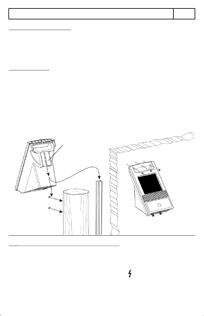
Step 4: Mount the Energiser
Wooden
Post
T-Post
Wall
Mounting
On the back of the energiser is a built-in mounting slot that can be used on a wood
post or steel T-post. See Diagram 2.
Face the solar panel due South (if in the northern hemisphere) out of the way of
trees, buildings and other objects that will cast a shadow. Do not mount the
energiser on the ground.
Mounting Options:
T-Post. Slide the mounting slot on the back of energiser over the top of the post.
Wooden Post: Screw in 2 large pan-headed screws into the wooden post, one
above the other in a line with the heads 1cm proud of the surface. Slide the mounting
slot on the back over these 2 proud screw heads. (screws not provided)
Wall: The carry handle of the energiser has 3 wall-mounting screw holes. Hold the
energiser against the wall and mark the position of the 3 holes (in a horizontal line).
Drill 3 holes (if necessary) then hold the energiser back in position and drive in 3
screws. (screws not provided)
Diagram 2
Mounting
slot
Step 5: Connect to the Fence and Ground System
Note: Ensure the energiser is OFF before connecting up or you may receive a shock.
Fence (Live) Connection
1. If using a set of fence leads, use the red lead wire. The ring terminal on one end
of the lead is to connect to the red (Live) terminal ( ).
2. Remove the red knob and one washer, place on the ring terminal.
3. Replace the washer and red knob and hand tighten. DO NOT use pliers or other
mechanical means to tighten the knobs or they may be damaged.
4. Properly connect the other end of the lead with the red crocodile clip to the fence
wire making sure it has a good electrical connection.
continued....
Page 9

ENERGISER INSTALLATION continued
5. If not using a set of fence leads, and using a piece of hook-up wire, strip the ends
of the wire and make a loop or “J” shape on one end.
6. Remove the red knob and one washer and loop over the end of the hook-up wire
over the terminal bolt.
7. Replace the washer and red knob and hand tighten. DO NOT use pliers or other
mechanical means to tighten the knobs or they may be damaged.
8. Properly connect the other end of the hook-up wire to the fence wire with suitable
wire clamps.
Ground Connection
1. If using a set of fence leads, use the black lead wire. The ring terminals on either
end of the lead is to connect to the black (Ground) terminal ( ).
2. Remove the black knob and one washer, place on one ring terminal.
3. Replace the washer and black knob and hand tighten. DO NOT use pliers or
other mechanical means to tighten the knobs or they may be damaged.
4. Properly connect the other end of the black lead with the ring terminal to the
ground rod making sure it has a good electrical connection.
5. If not using a set of fence leads, and using a piece of hook-up wire, strip the ends
of the wire and make a loop or “J” shape on one end.
6. Remove the black knob and one washer and loop over the end of the hook-up
wire over the terminal bolt.
7. Replace the washer and black knob and hand tighten. DO NOT use pliers or
other mechanical means to tighten the knobs or they may be damaged.
8. Properly connect the other end of the hook-up wire to the ground rod with suitable
wire clamps. Refer to Diagram 3.
Ground rod
Live Fence Wire
Live Fence Wire
Live Fence Wire
Connect the Black terminal
( ) to the Ground rod
using the Black lead.
Connect the Red terminal
( ) to the Fence line using
the Red lead.
Mark the top
of the ground
rods as a hazard
Diagram 3
Note:10 to 14 gauge insulated lead-out
wire (rated 20,000V) is commonly
used for these connections.
Page 10
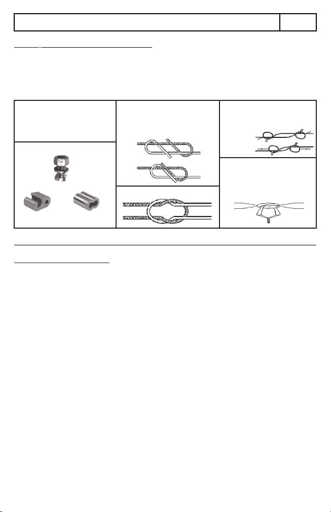
Diagram 4: Wire Splicing and Connections
Wire Tap Wire Splicing
For best results when connecting electric
fence wire, polywire or polytape, only use
the following methods to protect your
fence wire from corrosion and increase
the reliability of full power being distributed
to the rest of your electric fence.
Wire Connections
Split Bolt
When joining fence wire anywhere on the
Sleeve
fence, be sure to use B Figure 8 or Reef Knot.
Wire Joints
See Below.
Figure 8 Knot
Step 1
Reef Knot
Step 2 Knotting Polytape
Knotting Polywire
When knotting polywire, be sure to double
the ends of the connecting fence wire.
Then tie a Slip Knot, as shown below.
Pull Wire
to Tighten
To connect polytape, first start with a
standard knot. Be sure to leave between
3-4” of extra tape. Peel back around 2.5”
of the tape, exposing the conductive wires.
Twist the two wires together to make the
connection complete.
ENERGISER INSTALLATION continued
Properly connect the hook-up wire from the energiser to the fence line or ground
system using appropriate connection methods to ensure a good connection.
Joints along the fence line also need to be well made to ensure a good electrical
connection. Some common methods are shown in Diagram 4.
Step 6: Wire Splicing and Connections
Put the switch on the bottom of the energiser to the ON position. Wait for it to go
through its battery voltage check sequence. After 3 seconds of no flashes the red
light should show a short flash once every 1.4 seconds if the battery is fully charged.
If the battery is low it will show a short flash every 2 seconds due to the battery saver
mode.
Note: It is highly recommended that you buy an electric fence digital volt mater.
This is the only way to be confident about the fence voltage.
Step 7: Energise the fence
Page 11

SOLAR PANEL MAINTENANCE
CAUTION
Only use a 6V rechargeable
sealed lead-acid battery.
The battery comes pre-installed and already tested and connected from the factory.
The easiest way to charge this 6V battery is to follow the battery charging
instructions in Step 1.
If you put the energiser in full sun for 5 days straight and the battery voltage is still
under 5.75V (4 light flashes or less), then you may need to replace the battery, but
you should only have to do this after several years of use.
Referring to Diagram 5:
1. Turn the energiser over, face-
down. (make sure the solar panel
is not resting on any hard objects).
2. Remove the single battery case screw
with a Philips screwdriver.
3. Slide the battery case down first to
release, then pull it out.
4. The battery is connected by 2 wires.
Disconnect the wires from the top of
the battery.
5. Pull the battery out of the battery case.
Installation of a new battery is the
reverse of the 5 steps above.
Make sure the red wire is connected to
the positive terminal of the battery (+)
and the black wire is connected to the
negative terminal of the battery (-).
BATTERY REPLACEMENT
● Every few months use a damp cloth (with water only) and a dry cloth to clean the
solar panel of dust or dirt. This will help maximise solar panel efficiency.
● If snow gets on the solar panel simply wipe it off.
STORING THE ENERGISER
● When storing the energiser for long periods (for example; over the winter), take
out the energiser and place it strong, direct sunlight for 2 days, every 4 months
with the switch in the “CHARGE” position. This is to make sure the battery is
topped up and will not be discharged below 11V which will damage the battery.
● Put the switch back into the “OFF” position before putting back into storage.
Battery Specifications
6V 4.5Ah Rechargeable Sealed Lead-Acid type
F1 terminals (187 series / 4.8mm male)
Size: 70mm x 47mm x 107mm high
Diagram 5
Page 12

Product Specifications:
● Solar-powered fence energiser, 6V internal battery, incorporated solar panel.
● ON / OFF / CHARGE modes – User selectable.
● Battery Voltage check indicator – LED indicator used to show battery voltage.
● 0.16J output energy.
● Secure wall-mounting or post-mounitng.
● IP54 ingress protection.
● ABS enclosure with UV stabilisation.
● Complies with: EN 60335-1 & 60335-2-76
Item No. 31001120 Rev. 23032022
A copy of this manual is available online.
Scan the QR code:
Or visit the Forcefield website:
www.forcefield.ie
SAVE THESE INSTRUCTIONS
Table of contents
Other Forcefield Power Supply manuals


