Foremost VERANDA CLASSICS Harmony User manual

1
Harmony Outdoor Gas Fire Pit with Porcelain Tiles
ITM./ART.#: FIGS545GFPB
ANSI Z21.97/CSA 2.41-2014
Outdoor Decorative Gas Appliances
Installer: Leave these instructions with consumer.
Consumer: Keep these instructions for further reference.
Questions,Problems,Missing Parts? Before
returning to your retailers, contact Foremost Groups
Customer Relations Department toll free number at
1-800-443-1410 (USA), between the hours of 8:30
am and 5:00 pm EST, Monday thru Friday or fax
your request to (973) 428-8026 or email us at

2
1. The installation must conform with local codes or, in the absence of local codes, with the National Fuel Gas
Code, ANSI Z223.1●NFPA 54; National Fuel Gas Code; Natrual Gas and Propane Installation Code, CSA
B149.1; or Propane Storage and Handling Code, CSA B149.2, as applicable.
2. The appliance must be isolated from the gas supply piping system by closing its individual manual shutoff
valve during any pressure testing of the gas supply piping system at test pressures equal to or less than 1/2
psi (3.5 kPa).
3. The maximum inlet gas supply pressure is 250 psi.
4. The appliance area must be kept clear and free from combustible mateirals, gasoline, and other flammable
vapors and liquids.
5. Do not use this appliance if any part has been under water. Immediately call a qualified service technician to
inspect the appliance and to replace any part of the control system and any gas control that has been under
water.
6. Children and adults should be alerted to the hazards of high surface temperatures and should stay
away to avoid burns or clothing ignition.
7. Young children should be carefully supervised when they are in the area of the appliance.
8. Clothing or other flammable materials should not be hung from the appliance or placed on or near the
appliance.
9. Any guard or other protective device removed for servicing the appliance shall be replaced prior to
operating the appliance.
10. Installation and repair should be done by a qualified service person. The appliance should be
inspected before use and at least annually by a qualified service person. More frequent cleaning may
be required as necessary. It is imperative that the control compartment, burners, and circulating air
passageways of the appliance are kept clean.
11. CAUTION: The propane gas pressure regulator provided with this appliance must be used. This regulator is
set for an outlet pressure of 11 inches water column.
12. DO NOT burn solid fuels in this appliance.
13. This outdoor gas appliance is for Outdoor Use ONLY.
14. This outdoor gas appliance is not intended to be installed in or on recreational vehicles and/or boats.
15. This outdoor appliance is not for use on wood decks or other flammable surface.
16. Before each use of this gas appliance, open the door and/or the LP (Liquid Propane) Tank Drawer and
inspect the hose. If there is evidence of excessive abrasion or wear or if the hose is damaged, the hose
assembly must be replaced prior to the appliance being put into operation. Use only the replacement hose
assembly specified in this manual. Make sure to leak test.
17. Before each use of this gas appliance, inspect the burner, the burner must be replaced prior to the appliance
being put into operation if it is evident that the burner is damaged. Use only the replacement burner specified
in this manual.
18. Make sure to properly locate the gas hose including locating the hose out of pathways where people may tip
over it or in areas where the hose may be subject to accidental damage.
19. Keep the fuel supply hose away from any heated surface.
20. Never use this appliance closer than 10 feet from anything flammable, including houses or overhead tree
branches.
21. Never use gasoline, kerosene, or any other liquid fuel to start a fire.
22. Always maintain a safe distance from the fire.
23. Always supervise children around the fire.
24. Never leave a fire unattended.
25. The appliance is hot during and after use, always allow ample cooling time before touching or moving.
IMPORTANT SAFETY INFORMATION

3
1. The LP-gas supply cylinder to be used must be constructed and marked in accordance with the U.S.
Deparment of Transportation (D.O.T.) Specifications for LP-Gas Cylinders, or the Standard for Cylinders,
Spheres and Tubes for Transportation of Dangerous Goods and Commission, CAN/CSA-B339, as
applicable.
2. The LP-gas supply cylinder to be used must have a listed overfilling prevention device (See Figure 1).
3. The LP-gas supply cylinder to be used must have a cylinder connection device compatible with the
connection for the appliance.
4. A self contained LP-gas cylinder for use with this appliance must have a capacity of 20 lbs. cylinder (Height
about 18 in., Tank Body about dia12 in., Base about dia8 in.).
5. The cylinder supply system must be arranged for vapor withdrawl.
6. The cylinder used must include a collar to protect the cylinder valve.
7. This appliance shall be used only outdoors in a well-ventilated space and shall not be used in a building,
garage or any other enclosed space.
8. When this appliance is not in use, the gas must be turned off at the supply cylinder.
9. Storage of this appliance indoors is permissible only if the cylinder is disconnected and removed from the
Appliance.
10. Cylinders must be stored outdoors in a well-ventilated area out of the reach of children, Disconnected
cylinders must have threaded valve plugs tightly installed and must not be stored in a building, garage or any
other enclosed areas.
11. This appliance is certified by CSA (Canadian Standards Association) to ANSI Z21.97/CSA 2.41-2014,
Outdoor Decorative Gas Appliances.
12. The gas hose is routed through two “U” rings to prevent the hose from coming in contact with the burner. DO
NOT remove the hose from the “U” rings (See Figure 2).
IMPORTANT SAFETY INFORMATION ABOUT
PROPANE (LP) GAS
SPECIFICATIONS
Figure 1 Figure 2
“U” ring

4
E
F
G
H
A
B
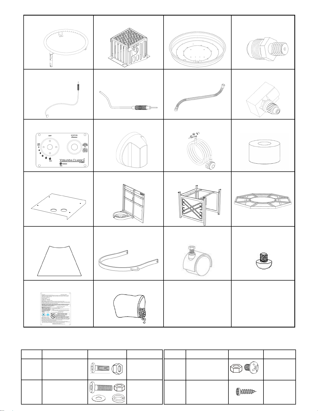
PACKAGE CONTENTS
ASSEMBLY INSTRUCTIONS
1. Carefully unpack all parts from the box, compare parts with package content listed above, make sure all parts
are present before beginning assembly of product. If any part is missing or damaged, do not attempt to
assemble the product. Contact customer service for replacement parts.
2. Fix the Table Top Frame (A) onto the Base Assembly (B) with Stud (E), Washer (F), Spring washer (G) and
Nut (H), screw the Nut (H) tightly by using the Wrench (I), (see Figure 3).
Hardware Used:
E Stud (5/16”*30) x 4
F Washer x 4
G Spring washer x 4
H Nut x 4
PART DESCRIPTION PICTURE QUANTITY
E Stud (5/16”*30) 4
F Washer 4
G Spring wahser 4
H Nut (5/16”) 4
I Wrench 1
Figure 3
A
B
C
E
F
G
H
D
PART DESCRIPTION QUANTITY
A Table top frame 1
B Base assembly 1
C Porcelain tile
10pcs
(8pcs for assembly,
2pcs for replacement)
D Lava rock (15.4 lbs) 1 pkg

5
pilot box
D
B
A
C
“U” ring
knob
black handle
Figure 6
3. Put the Porcelain Tile (C) into Table Top Frame (A), (See Figure 4).
4. Put the Lava Rock (D) around the burner, then remove the label from the pilot box (see Figure 5). A gas fire
pit requires 15.4 lbs lava rock.
WARNING: Keep children away during assembly, as this item contains lava rock, which are small pieces and
can be swallowed by children.
5. Open the door, place the gas cylinder into the cylinder holder, connect the regulator, screw the black handle
clockwise to tighten, turn the black handle counterclockwise to remove. The hose must point down. The knob
on the control panel is turned all the way to the “OFF” position when the fire pit is NOT in use. Make sure the
hose is routed through the two “U” rings to prevent the hose from coming in touch with the burner or the
ground. DO NOT remove the hose from the “U” rings (See Figure 6).
Figure 4
Figure 5

6
Figure 7
6. Secure the cylinder by tightening clockwise the butterfly screw found on the cylinder holder (see Figure 7), so
that the cylinder cannot move from side to side or fall down.
Natural gas conversion must be performed only by natural gas provider or service company.
1. Disconnect the propane hose from the gas valve (see Figure 8).
Figure 8
2. Unscrew and disconnect the propane orifice from the bellows (see Figure 9). Propane orifice (dia2.15mm
size) is painted with red mark.
Figure 9
propane hose
gas valve
propane orifice
bellows
propane orifice
bellows
NATURAL GAS CONVERSION
STOP STOP

7
natural gas hose
gas valve natrual gas supply
piping system
natrual gas fixture
Figure 10
Figure 11
4. Connect the natural gas hose with the gas valve by screwing clockwise tightly (see Figure 11). Plug the
natural gas fixture into the natrual gas supply piping system (see Figure 12).
Figure 12
Figure 13
3. Replace the propane orifice with the natural gas orifice, screw the natural gas orifice with the bellows tightly,
then connect and tighten the natural gas orifice with inlet tube (see Figure 10). Natural gas orifice (dia4.30mm
size) is painted with black mark.
natural gas orifice
inlet tube
bellows
5. Stick the conversion label onto the propane rating plate (see Figure 13).
conversion label propane rating plate
8
BATTERY
LEAK TEST
To prevent fire or explosion hazard when testing for a leak:
1. Always perform the leak test as described below before lighting this appliance or each time the cylinder is
connected for use.
2. Do not smoke or allow other sources of ignition in the area while conducting a leak test.
3. Conduct the leak test outdoors in a well-ventilated area.
4. Do not use matches, lighters or a flame to check for leaks.
5. Do not use this appliance until any and all leaks are corrected. If you are unable to stop a leak, disconnect
the propane supply. Call a gas appliance service shop or your local propane gas supplier.
cylinder-regulator connection (Figure 15) gas valve-bellows connection (Figure 16)
Figure 14
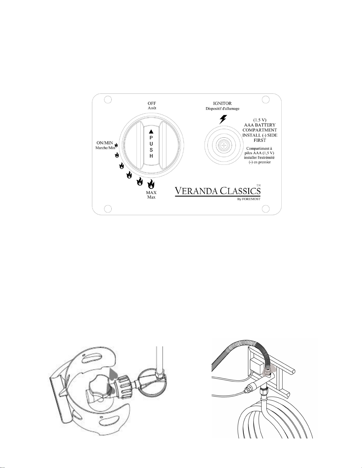
Make sure the control knob is in the “OFF” position. Unscrew the push button cap on the ignitor module located
on the control panel to access the battery compartment. The ignitor module requires one AAA size battery (See
Figure 14).
WARNING:
1. Please observe proper polarity and use the correct battery type when placing or replacing the battery.
Improper installation could result in ignition failure.
2. Please remove the battery if consumed or if product is to be left unused for a long period of time.

9
To perform a leak test:
1. Make 2~3 oz. of leak solution by mixing one part liquid dishwashing detergent and three parts water.
Noted: make sure control knob is “OFF”.
2. Apply several drops of solution where the cylinder attaches to regulator (see Figure 15), inspect the solution
at the connection looking for bubbles. If NO bubbles appear, the connection is secure. If bubbles appear, the
connection has the leak, disconnect the regulator, reconnect, perform another leak check. If you continue to
see bubbles after several attempts, cylinder valve is defective and should be returned to cylinder’s supplier.
3. Apply several drops of solution where gas valve attaches to bellows (see Figure 16), where gas valve
attaches to hose (see Figure 17), and where inlet tube attaches to bellows (see Figure 18). If NO bubbles
appear, the connections are secure. If bubbles appear, the connection has the leak, disconnect, reconnect,
perform another leak check. If you continue to see bubbles after several attempts, the part is defective and
should replace the part.
inlet tube-bellows connection (Figure 18)
gas valve-hose connection (Figure 17)
LIGHTING INSTRUCTIONS
1. Push in gas control knob slightly and turn to “OFF”.
2. Turn gas control knob the “ON/MIN”.
3. Push in gas control knob all the way and hold. Continue to press the ignition button for 15 seconds.
4. If the burner does not light in 15 seconds, release the knob and it will pop back out. Wait 5 minutes before
attempting to light the burner again, repeat step 1 to 3.
1. Push in gas control knob slightly and turn to “OFF”.
WARNING: For your safety, read and follow the Lighting Instructions in this manual and in the Rating Plate on
the appliance. IMPROPER LIGHTING PROCEDURES COULD RESULT IN A FIRE HAZARD OR EXPLOSION
HAZARD OR PROPERTY DAMAGE, INJURY OR LOSS OF LIFE.
TO TURN OFF GAS
Figure 19
ignition button
gas control knob
10
CARE AND MAINTENANCE
To enjoy the outstanding performance from your fire pit, make sure you perform the following activities on a
regular basis:
1. Use warm soapy water for cleaning. Never use flammable or corrosive cleaning agents.
2. While cleaning the fire pit, make sure to keep the area around the burner dry at all times. DO NOT submerge
the control valve assembly. If the gas control is submerge in water, DO NOT use it. It must be replaced.
3. Air flow must be unobstructed. Keep controls, burner, and circulating air passageways clean. Signs of
possible blockage include:
(1). Gas odor with extreme yellow tipping of flame.
(2). Fire pit does NOT reach the desired temperature.
(3). Fire pit flame is excessively uneven.
(4). Fire pit makes popping noises.
(5). Spiders and insects can nest in burner or orifice. This dangerous condition can damage fire pit and
render it unsage for use. Clean burner holes by using a heavy-duty pipe clearer. Compressed air may
help clear away small particles.
4. Carbon deposits may create a fire hazard. Clean burner with warm soapy water if any carbon deposits
develop.
NOTE: Always allow fire pit to cool COMPLETELY before attempting service or maintenance.
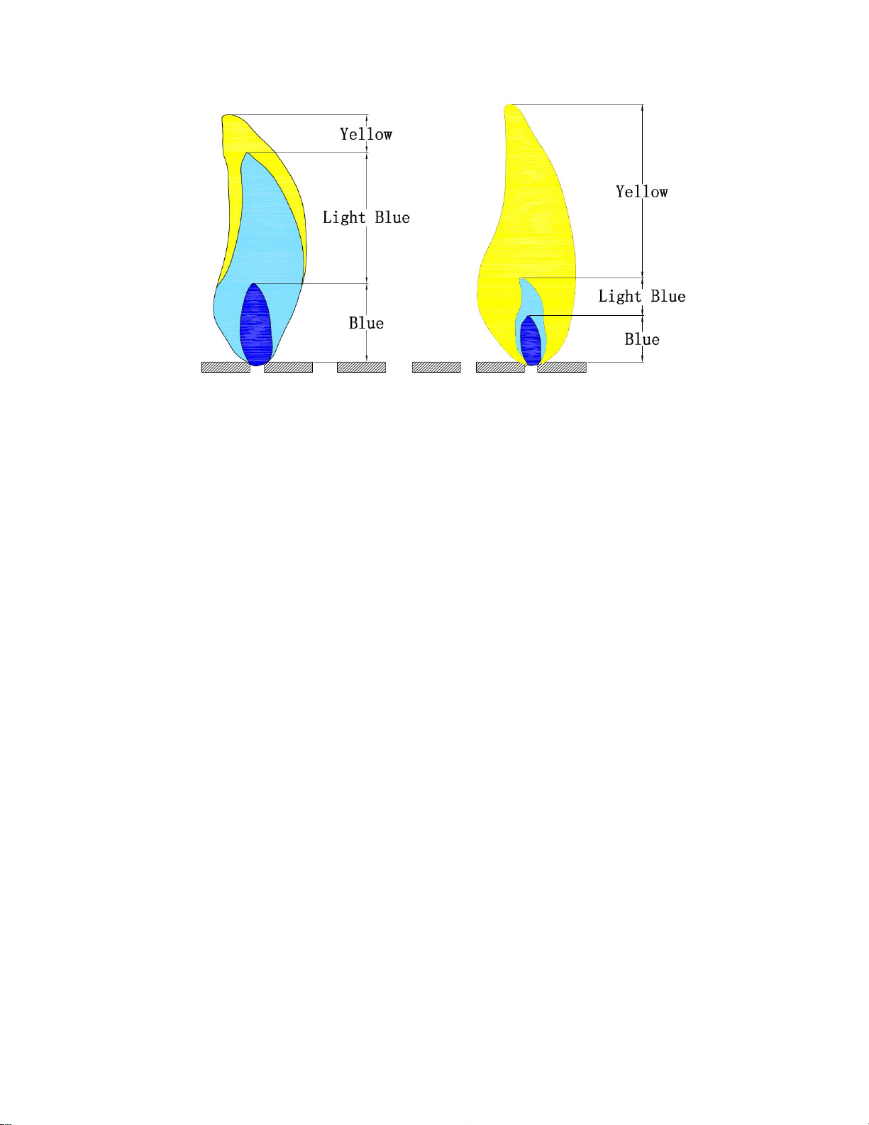
Observe Flame Height When Lit: Flame should be a blue / yellow color between 1~2 in. height (see Figure 20).
Good Bad
Figure 20

11
PARTS LIST
PART DESCRIPTION QUANTITY
01 Burner 1
02 Pilot box 1
03 Fire bowl 1
04 Orifice 1
05 Thermocouple 1
06 Electrode tip 1
07 Bellows 1
08 Pulse ignition system 1
09 Control panel 1
10 Gas control knob 1
11 Hose assembly 1
PART DESCRIPTION QUANTITY
12 Bakelite 4
13 Heat shield 1
14 Door 1
15 Base 1
16 Table top frame 1
17 Porcelain tile
10pcs (8pcs for
assembly, 2pcs for
replacement)
18 Gas cylinder protective ring 1
19 Wheel assembly 1
20 Foot glider (M8) 4
21 Rating plate 1
22 R
21
14
01
06
10
08
11
04
05
07
15
09
02
03
12
13
17
18
19
20
16
12
Lava rock
ILLUSTRATED PARTS LIST
HARDWARE CONTENTS
PART DESCRIPTION IMAGE QUANTITY
AA Bolt (1/4”x25),
Nut (1/4”) 4 sets
BB
Bolt (1/4”x55),
Nut(1/4”),Washer
Spring Washer
4 sets
PART DESCRIPTION IMAGE QUANTITY
CC Bolt (M4*10),
Nut (M4) 8 sets
DD Screw (T5*15) 4
22
04
Burner
01 Pilot box
02 03 Fire bowl
Electrode tip
Thermocouple
Orifice
Bellows Pulse ignition system
Control panel Bakelite
Hose assemblyGas control knob
Heat shield Door Base
05 06 07 08
09 10 11 12
13 14 15 16
17 18 Gas cylinder
protective ring
19 20
21
Table top frame
Porcelain tile
Wheel assembly Foot glider (M8)
Rating plate
13
PART DESCRIPTION IMAGE QUANTITY
GG
Bolt (1/4”x25),
Washer, Spring
washer
3 sets
HH Wrench 1
II Hex screw driver 1
REPLACEMENT PARTS LIST
22 SR-GFP-163E-LP Rating plate (for Liquid Propane use)
23 SR-GFP-164E-NG Rating plate (for Natural Gas use)
24 H-LVRK Lava rock
25 SR-GFP-545 Hardware pack
NO. Part# Description
01 H-GFP-001 Burner
02 H-GFP-002 Pilot box
03 H-GFP-003 Fire bowl
04 H-GFP-004-LP Orifice (for Liquid Propane use)
05 H-GFP-004-NG Orifice (for Natural Gas use)
06 H-GFP-005 Thermocouple
07 H-GFP-006 Electrode tip
08 H-GFP-007 Bellows
09 H-GFP-008 Pulse ignition system
10 H-GFP-009 Control panel
11 H-GFP-010 Gas control knob
12 H-GFP-011 Hose assembly
13 H-GFP-012B Bakelite
14 SR-GFP-110B Heat shield
15 SR-GFP-160 Table top frame
16 SR-GFP-161 Base
17 SR-GFP-162 Door
18 X-GFP-PCTL Porcelain tile
19 SR-GFP-144 Gas cylinder protective ring
20 SR-GFP-145 Wheel assembly
21 SR-GFP-146 Foot glider
HARDWARE CONTENTS
PART DESCRIPTION IMAGE QUANTITY
EE
Stud (5/16”*30)
Washer,
Spring washer
Nut (5/16”)
4 sets
FF
Bolt (1/4”x50),
Washer, Spring
washer
1 set

14
Firepits
Burner, cast aluminum & steel fire pit bowls, all mechanical parts and fittings to control panel and burner assembly, and all aluminum fire pit
tops that are not cast aluminum are warranted for a period of one (1) year from original date of purchase, against defects in material and
or workmanship. Rust is not covered.
Frames
Frames are warranted to be free from defects in materials and workmanship for a period of two (2) years. Damage to frames or welds due to
improper assembly or exposure to water and sub-freezing temperatures, is not covered. Breakage that is a result of product being dropped,
acts of God, acts of war, etc. are not covered.
Finish
The finish is warranted against peeling, cracking, or blistering for a period of one (1) years provided the product has not been scratched or
abraded. Scratches and chips resulting from normal wear and tear are not covered. Fading resulting from exposure to elements is not
covered. Stains as a result of chemical spills and certain food items are not covered.
Table Tops
All table tops are warranted for a period of one (1) year from original date of purchase, against defects in material and or workmanship.
Breakage, discoloration, staining, and or any other weather related issues are not covered.
Wicker Weave and/or Straps (if applicable)
Wicker weave and/or Straps are warranted for a period of one (1) year against separation or tearing. Fading or discoloration resulting from
exposure to the elements, chemicals, or from spills is not covered.
Warranty Exclusions
Failure caused by unreasonable or abusive use. Firepits that were clearance items, display models or items purchased in an "as is" condition,
freight damage, firepit damaged by acts of nature, vandalism, fire, abuse, lack of proper care and maintenance, or improper assembly; straps
and normal fading or discoloration from exposure to elements, oils, spills, fluids or chemicals; Table top against breakage; hardware against
corrosion or rusting; buckling or splitting of tubing resulting from exposure to water and freezing temperatures; glass table tops, purchased or
replacement parts; plastics. Also excluded: loss of use of time and or inconvenience, money, travel, packaging or any other consequential or
incidental damages. In no event shall Foremost Groups Inc. responsibility exceed the value of the replacement product. Warranty is to the
original purchaser when items are purchased from one of our authorized retailers and is not transferable. All warranty claims must be
submitted with a dated register receipt within the warranty period. Should replacement of the warranted item be unavailable, Foremost Groups
Inc. reserves the right to substitute items of our choice similar in style, color and quality. For quality control purposes and verification, we
reserve the right to request photographs of the damage item(s). The terms of this warranty are subject to change without notice.
To obtain warranty service please contact Foremost Groups Customer Relations Department toll free number at 1-800-443-1410 (USA),
between the hours of 8:30 am and 5:00 pm EST, Monday thru Friday or fax your request to (973) 428-8026 or email us at
customerservice@foremostgroups.com or visit our website at www.foremostgroups.com.
DISTRIBUTED BY:
Foremost Groups, Inc.
906 Murray Road,
East Hanover, NJ 07936
Web: www.foremostgroups.com
Email: customerservice@foremostgroups.com
Toll Free: 1-800-443-1410 (US)
2 YEAR LIMITED WARRANTY
This manual suits for next models
1
Table of contents
Other Foremost Outdoor Fireplace manuals


Popular Outdoor Fireplace manuals by other brands

Forno Bravo
Forno Bravo Calore2G75 Assembly and operation manual

Endless Summer
Endless Summer WAD15129MT owner's manual

Bond
Bond Castle Rock HYFP50095-84 manual

pleasant hearth
pleasant hearth HARMONY manual

Landmann
Landmann CITY LIGHTS Montcello Assembly instructions

Nordpeis
Nordpeis Napoli Garden FP-NAPGR-100 Assembly instructions


Blumfeldt
Blumfeldt 10031003 manual

Outdoor GreatRoom Company
Outdoor GreatRoom Company COR-1264 installation instructions

Montigo
Montigo CFPO-2 Installation & maintenance manual

Lava Heat Italia
Lava Heat Italia Lorenzo owner's manual

Kenwood
Kenwood AT550 instructions

Woodbridge
Woodbridge SS-36 OWNER'S OPERATION AND INSTALLATION MANUAL