1.
This appliance is only for use with the type of
gas indicated on the rating plate. This appliance
is not convertible for use with other gases.
2. Do not place propane/LP supply tank(s) in-
side any structure. Locate propane/LP supply
tank(s) outdoors (propane/LP units only).
3. If you smell gas
• shut off gas supply
• do not try to light any appliance
• do not touch any electrical switch; do not use
any phone in your building
• immediately call your gas supplier from a
neighborʼs phone. Follow the gas supplierʼs
instructions
• if you cannot reach your gas supplier, call
the fire department
6. To prevent the creation of soot, follow the
instructions in Cleaning and Maintenance
section.
7.Before using furniture polish, wax, carpet
cleaner or similar products, turn heater off. If
heated, the vapors from these products may
create a white powder residue within burner
box or on adjacent walls or furniture.
8.This fireplace needs fresh air ventilation to run
properly. This fireplace has an Oxygen Deple-
tion Sensing (ODS) safety shutoff system. The
ODS shuts down the fireplace if enough fresh
air is not available. See Air for Combustion
and Ventilation, page 6. If fireplace keeps
shutting off, see Troubleshooting, page 21.
9. Do not run fireplace
• where flammable liquids or vapors are used
or stored
• under dusty conditions
10. Do not use this fireplace to cook food or burn
paper or other objects.
SAFETY INFORMATION
Continued
11.Do not use fireplace if any part has been
exposed to or under water. Immediately call
a qualified service technician to inspect the
fireplace and to replace any part of the control
system and any gas control which has been
under water.
12.Turn fireplace off and let cool before servicing.
Only a qualified service person should service
and repair fireplace.
13. Operating fireplace above elevations of 4,500
feet could cause pilot outage.
14.
To prevent performance problems in propane/LP
units, do not use propane/LP fuel tanks of less
than 100 lbs. capacity (propane/LP units only).
15.
Provide adequate clearances around air
openings.
LOCAL CODES
*Available from:
American National Standards Institute, Inc.
1430 Broadway
New York, NY 10018
National Fire Protection Association, Inc.
Batterymarch Park
Quincy, MA 02269
State of Massachusetts: The installa-
tion must be made by a licensed plumber
or gas fitter in the Commonwealth of
Massachusetts.
Sellers of unvented propane or natural
gas-fired supplemental room heaters shall
provide to each purchaser a copy of 527
CMR 30 upon sale of the unit.
Vent-free gas products are prohibited for
bedroom and bathroom installation in the
Commonwealth of Massachusetts.
Install and use fireplace with care. When an
appliance is for connection to a fixed piping
system, the installation must conform with local
codes, or in the absence of local codes, with The
National Fuel Gas Code ANSI Z223.1/NFPA 54*,
International Fuel Gas Code, Natural Gas and
Propane Installation Code, CSA B149.1, or Propane
Storage and Handling Code, B149.2, as applicable.
4. This fireplace shall not be installed in a bed-
room or bathroom. Do not use this fireplace
as a wood-burning fireplace.
5. Children and adults should be alerted to the
hazards of high surface temperatures and
should stay away to avoid burns or clothing
ignition.
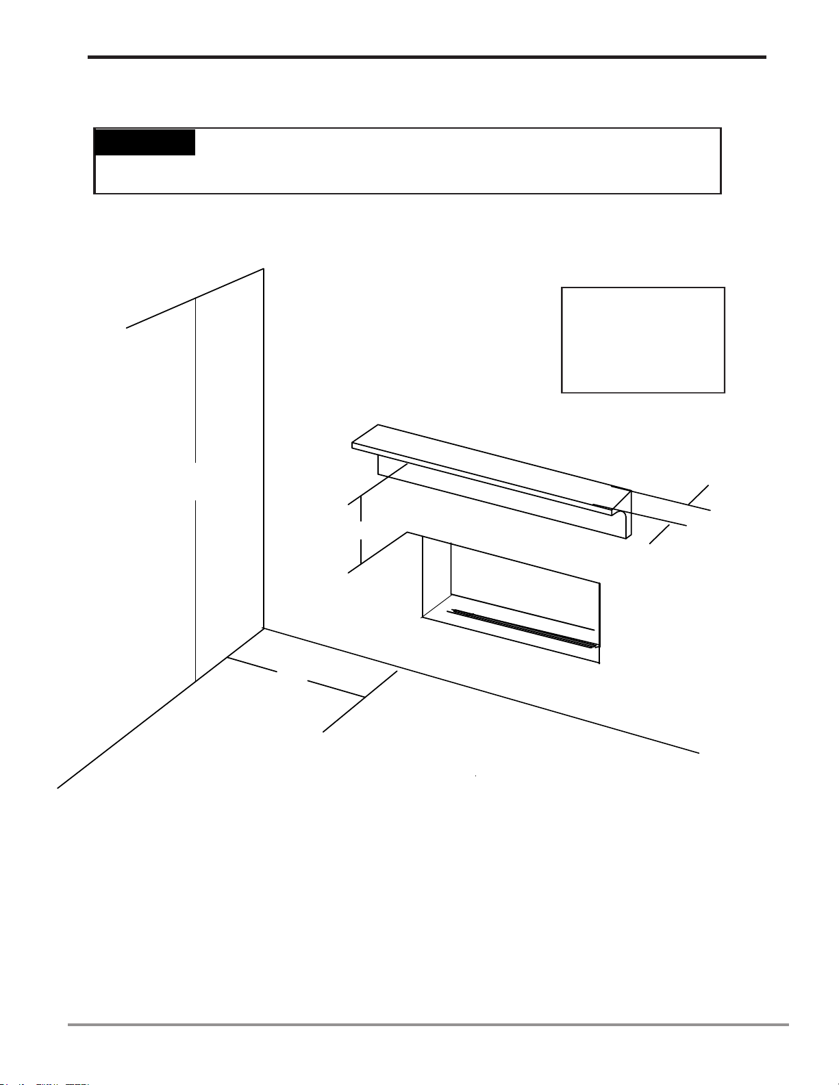
Keep the appliance area clear
and free from combustible
materials, gasoline and other
flammable vapors and liquids.