Forenex FR-E2S Series User manual
www.forenex.com.tw -1-
FR-E2Sxy
Ethernet to Serial interface
Reference Manual (Preliminary)
Version: 0.4.2
benson Lon Yu
Approved By Checked By Prepared By
***The content of this document is subject to be change without notice.***

www.forenex.com.tw -2-
Record of revision:
Version Revise Date Page Description
0.1
0.3.5
0.4.0
0.4.1
0.4.2
2014/11/28
2014/12/24
2014/12/31
2015/1/8
2015/05/18
First issue
For PCB revision 2.0
Added description about “ETH to SPI”
Modified E.g.1 and E.g.2 of A-1

www.forenex.com.tw -3-
Contents:
1. Introduction --------------------------------------------------------------------------- 4
1.1) General Description
1.2) System Architecture
1.3) Ordering Information
2. Features --------------------------------------------------------------------------------- 5
2.1) Ethernet Interface
2.2) Serial Interface
3. Electrical Characteristics ---------------------------------------------------------- 6
3.1) Recommended Operating Condition
4. Overview & Dimension ------------------------------------------------------------- 7
4.1) Dimension
4.2) Connector Overview
4.3) LED Status
5. Pin assignment of Connector ---------------------------------------------------- 9
5.1) W1: DC power wafer /Side entry
5.2) H1 : Serial communications Box-Header / Straight entry
5.3) Connect to RS-232/UART-TTL device
5.4) Connect to RS-232/UART-TTL device with flow control
5.5) Connect to RS-485 device
5.6) Connect to SPI slave device
6. Remote Configuration over Web Page------------------------------------------ 12
6.1) The first time to configure E2S board
6.2) Detail of Web Page
7. Ethernet Application Examples --------------------------------------------------- 17
7.1) Connect to the Host via Ethernet cable directly.
7.2) Connect to the Host via LAN.
7.3) Implement existing serial communications via Ethernet cable directly.
7.4) Implement existing serial communications via LAN.
7.5) Connect to Remote Server via INTERNET.
Appendix A. Flow Control Packet over Ethernet ---------------------------------- 21
Appendix B. Communication with SPI device over Ethernet ------------------25

www.forenex.com.tw -4-
1. Introduction
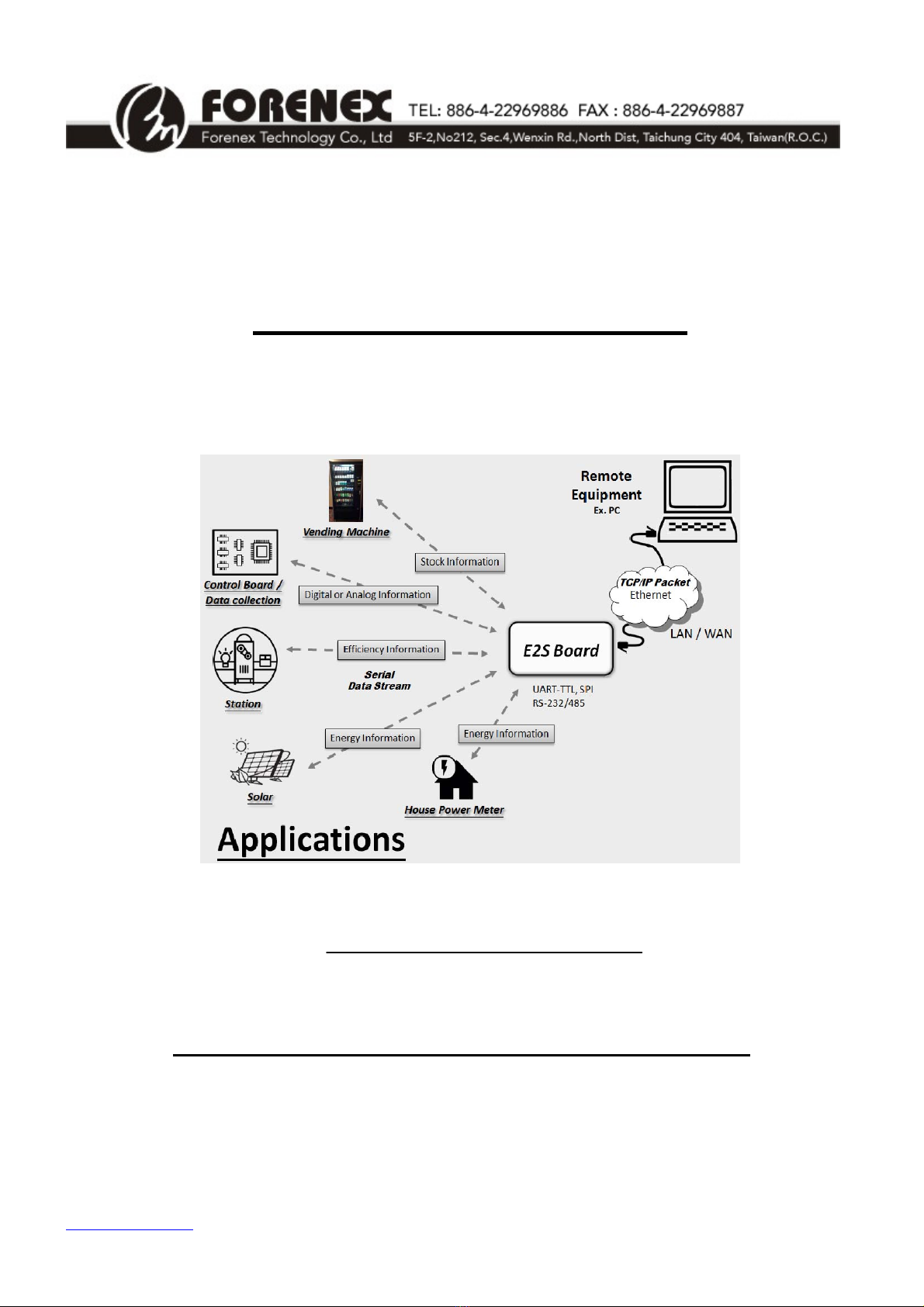
1.1) General Description
The E2S enables the serial target device to have an Ethernet function. Therefore, the
serial target device is able to connect a LAN/ WAN immediately without any hardware change.
The E2S is able to translate the protocol from TCP/IP packet to a kind of serial data
stream just likes RS-232, RS-485, UART-TTL or SPI depends on the different E2S model.
On the other hand, E2S is also to translate the data stream from a serial to TCP/IP packet.
It provides an easier way to connect Ethernet by DHCP client or DNS client. Besides, a
customized web page can configure E2S for an adaptive setting.
1.2) System Architecture
Figure 1. System Architecture.
1.3) Ordering Information
Part number : FR-E2S-xy
Serial interface:
• x =〝U〞- interface Uart-TTL.
=〝R〞- interface RS232.
=〝S〞- interface RS485.
=〝P〞- interface SPI.
• y =〝F〞- Commercial version.
=〝I〞- Industrial version.

www.forenex.com.tw -5-
2. Features
2.1) Ethernet Interface
Features Description
Ethernet Connector RJ45
Ethernet Speed/Duplex Auto-negotiation 10/100Mbps,
Full/Half duplex
Auto-MDIX Yes
Network Services DHCP client , DNS client ,
Web Server, Telnet server
Protocols Supported IP, UDP, TCP
2.2) Serial Interface
About the detail setting of Serial Interface refer to
Section 6) “Remote Configuration over Web Page”
zE2S-UF/ UI model, E2S-RF/RI model
1. UART TTL/ RS-232 signals: 5-wire (TX, RX, CTS, RTS, GND) or
3-wire(TX,RX,GND)
2. Flow control functions: None/ Hardware (CTS, RTS)/ Software (Xon, Xoff).
3. Baud Rate: UART_TTL Support up to 921600 bps.
RS232 Support up to 115200 bps.
zE2S-SF/SI model
1. RS-485 signals: 2-wire (A/Y+, B/Z-)
2. Automatically enable control for the transmitter/ receiver of RS-485.
3. Baud Rate: Support up to 115200 bps.
zE2S-PF/PI model
1. SPI signals: 5-wire (nSS, SCLK, MOSI, MISO, GND)
2. SPI working in the Master mode, support up to 1MHz clock.

www.forenex.com.tw -6-
3. Electrical Characteristics
3.1) Recommended operating condition:
GND = 0V, DC-IN = 5V, Ta = 25 ºC .
Parameter Symbol Min Typ. Max Unit Remark
DC IN 4.5 5 5.5 V
Power supply Current 250 300 mA
Power consumption Watt 1.25 1.5 W
In/out 3.3 V 5V tolerant
UART TTL
(E2S-UF/ UI model) Baudrate 1200 921600 bps
In ±15 V
out ±5 ±5.5 V
RS-232 signal level
(E2S-RF/RI model) Baudrate 1200 115200 bps
Note.1
In ±15 V
out 5V V
RS-485 signal level
(E2S-SF/SI model) Baudrate 1200 115200 bps
Note.2
In/out 3.3 V 5V tolerant
SPI Interface
(E2S-PF/PI model) Frequency 200K 1M Hz
0
80 ºC Commercial
Operation Temperature -25
80 ºC Industrial
Storage Temperature -40 130 ºC
Note.1 Detail refers to SP3232EET.
Note.2 Detail refers to ISL4485E.

www.forenex.com.tw -7-
4. Overview & Dimension
4.1) Dimension : 67mm(L) × 40mm(W) × Max. 19.5mm(H)
Unit:mm
Figure 2. Dimension Diagram.
www.forenex.com.tw -8-
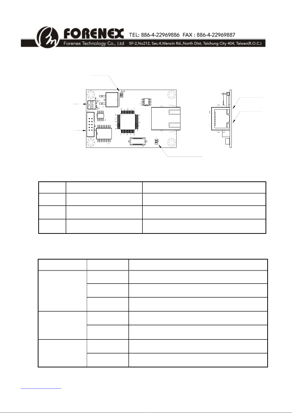
4.2) Connector Overview
J1RJ45
Ethernet
H12.0mmBoxheader
SerialSingal
W12.0mm2pin
DC5VInput
PowerLED
LinkLED
FullduplexLED
SpeedLED
Figure 3. Connector Overview
Name Description Remarks
W1 DC Power in Wafer 2 pin, 2.0mm.
H1 Serial signals connector Box Header 2x5 pin, 2.0mm, DIP Straight.
J1 Ethernet connector RJ-45
4.3) LED Status
Name Status Description
Light Ethernet was already linked.
Dark Ethernet is not connected
Link LED
Blinking When Ethernet is in receiving or transmitting state.
Light Ethernet work in 100BASE-TX mode.
Speed LED Dark Ethernet work in 10BASE-T mode.
Light Ethernet work in Full-duplex mode
Full duplex LED Dark Ethernet work in Half-duplex mode

www.forenex.com.tw -9-
5. Pin assignment of Connector
5.1) W1 : DC -in Wafer, 1x2 pin, 2.0mm, Side entry
SideView
Pin1
DC‐in
Pin2
GND
Pin No. Signal I/O Description
1 DC-IN I External DC 5V input
2 GND P Ground
5.2) H1: Serial communications Box-Header, 2x5 pin, 2.0mm, Straight entry
TopView
Pin
1
3
5
7
9
Pin
2
4
6
8
10
H1
ForE2S-UF/UI (UART TTL) and E2S-RF/RI (RS-232)
Pin No. Signal I/O Description
1 GND P Ground
2 RX I Receive Data form external Device
3 TX O Transmitte Data to external Device
4 - - -
5 GND P Ground
6 - - -
7 RTS O Request To Send
8 CTS I Clear to send
9 DC-IN P External DC input (as same as W1)
10 DC-IN P External DC input (as same as W1)

www.forenex.com.tw -10-
ForE2S-SF/SI (RS-485)
Pin No. Signal I/O Description
1 GND P Ground
2 - - -
3 - - -
4 A/Y+ IO Non-inverting driver in/out
5 GND P Ground
6 B/Z- IO Inverting driver in/output
7 - - -
8 - - -
9 DC-IN P External DC input (as same as W1)
10 DC-IN P External DC input (as same as W1)
ForE2S-PF/PI (SPI)
Pin No. Signal I/O Description
1 GND P Ground
2 MISO I Receive Data form external Device
3 MOSI O Transmitte Data to external Device
4 - - -
5 GND P Ground
6 - - -
7 SCLK O SPI Clock output
8 nSS O Slave Select output (Active low)
9 DC-IN P External DC input (as same as W1)
10 DC-IN P External DC input (as same as W1)

www.forenex.com.tw -11-
5.3) The E2S-RF/RI connects to RS-232 device in 3-wire,
The E2S-UF/UI connects to UART-TTL device in 3-wire.
Figure 4. Connect to 3-wire RS-232/UART-TTL device
5.4) The E2S-RF/RI connects to RS-232 device with flow control,
The E2S-UF/UI connects to UART-TTL device with flow control.
Figure 5. Connect to 5-wire RS-232/UART-TTL device
5.5) The E2S-SF/SI connects to RS-485 device.
Figure 6. Connect to RS-485 device
5.6) The E2S-PF/PI connects to SPI slave device.
Figure 7. Connect to SPI slave device

www.forenex.com.tw -12-
6. Remote Configuration over Web page
6.1) The first time to configure E2S board
There are two methods to connect between E2S board and Host PC for first time setting.
Due to the static IP of E2S board has default at 192.168.0.3, therefore, make sure the IP
address of host PC sets as same segment as 192.168.0.xxx.
(xxx is between 1 and 254, except 3).
a. PC connects to E2S board directly.
b. The E2S board connects to LAN.
6.2) Authentication page.
Open a web browser and enter http://192.168.0.3. When the login window appears,
set the user name to admin and set the password to admin.Click Login to continue.
Figure 8. Authentication page.

www.forenex.com.tw -13-
6.3) Basic Page:
This page can change Serial settings and Ethernet settings for E2S.
Figure 9. Basic settings page.

www.forenex.com.tw -14-
6.3.1) Serial Settings
Features Option Description
UART/RS-232/RS-485 E2S-UF/UI, E2S-RF/RI,
E2S-SF/SI
Serial Interface SPI E2S-PF/PI
For UART-TTL/RS-232/RS-485 Settings:
Features Default All option
Data Baud Rate 115200 921600, 115200, 57600, 38400,
19200, 9600, 4800, 2400, 1200
Data Bits 8 5, 6, 7, 8
Data Parity None Odd, Even, None
Stop Bits 1 1, 1.5, 2
Flow Control None Xon/Xoff, Hardware, None
For SPI Settings:
Features Default All option
Data Baud Rate 250KHz 1MHz, 750KHz, 500KHz,
400KHz, 250KHz, 200KHz
SPI Mode 0 0, 1, 2, 3
Differences between the SPI Mode 0~3:
MSB D6 D5 D4 D3 D2 D1 LSB
MOSI
CPOL = 0, CPHA = 0
Capture SCLK = Rising Edge
SCLK Inactive = Low Level
CPOL = 1, CPHA = 1
Capture SCLK = Rising Edge
SCLK Inactive = High Level
CPOL = 0, CPHA = 1
Capture SCLK = Falling Edge
SCLK Inactive = Low Level
CPOL = 1, CPHA = 0
Capture SCLK = Falling Edge
SCLK Inactive = High Level
nSS
Mode 0
Mode 1
Mode 2
Mode 3
SCLK

www.forenex.com.tw -15-
6.3.2) Network Settings
Features Option Description
Disable Default setting. (Note.1)
DHCP Client Enable
Static IP Address The default value is 192.168.0.3
Static Subnet Mask The default value is 255.255.255.0
Static Default Gateway The default value is 192.168.0.1
Static DNS Server The default value is 8.8.8.8
TCP Default.
Connection Type UDP
Transmit Timer (ms) The default value is 100
Please enter an integer between 10~65535.
Server Default setting.
Server/Client Mode Client
Listening Port
(under Server mode) The default value is 5000
Please enter an integer between 1024~65535
Destination Host Name/IP
(under Client mode)
The default value is 192.168.0.2 (Note.2)
Can accept either host name or IP address format;
e.q. you can enter “forenex.com.tw” or
“192.168.0.2”in this field.
Destination Port
(under Client mode) The default value is 5000 (Note.2)
Please enter an integer between 1024~65535
Disable Default setting.
Flow Control Packet Enable (Note.3)
Note.1 If “DHCP Client“ was disabled, E2S will use the default settings of static IP
Address and subnet mask.
Note.2 When E2S works under “Server Mode”, these settings are invalid.
Note.3 More detail please refers to “Appendix A. Flow Control Packet over Ethernet”.

www.forenex.com.tw -16-
6.4) Security Page
This page can change login account for Web server and Telnet server.
Figure 10. Security page.
Attentions:
**The Accessible IP Setting group must be used carefully. Once set these four IP list and
be enabled, E2S board can only be configured by these four IP address over Web page.
**When you change the accessible IP successful, you must reboot device to take it effect.
Please confirm settings before reboot device.
www.forenex.com.tw -17-
7. Ethernet Application Examples
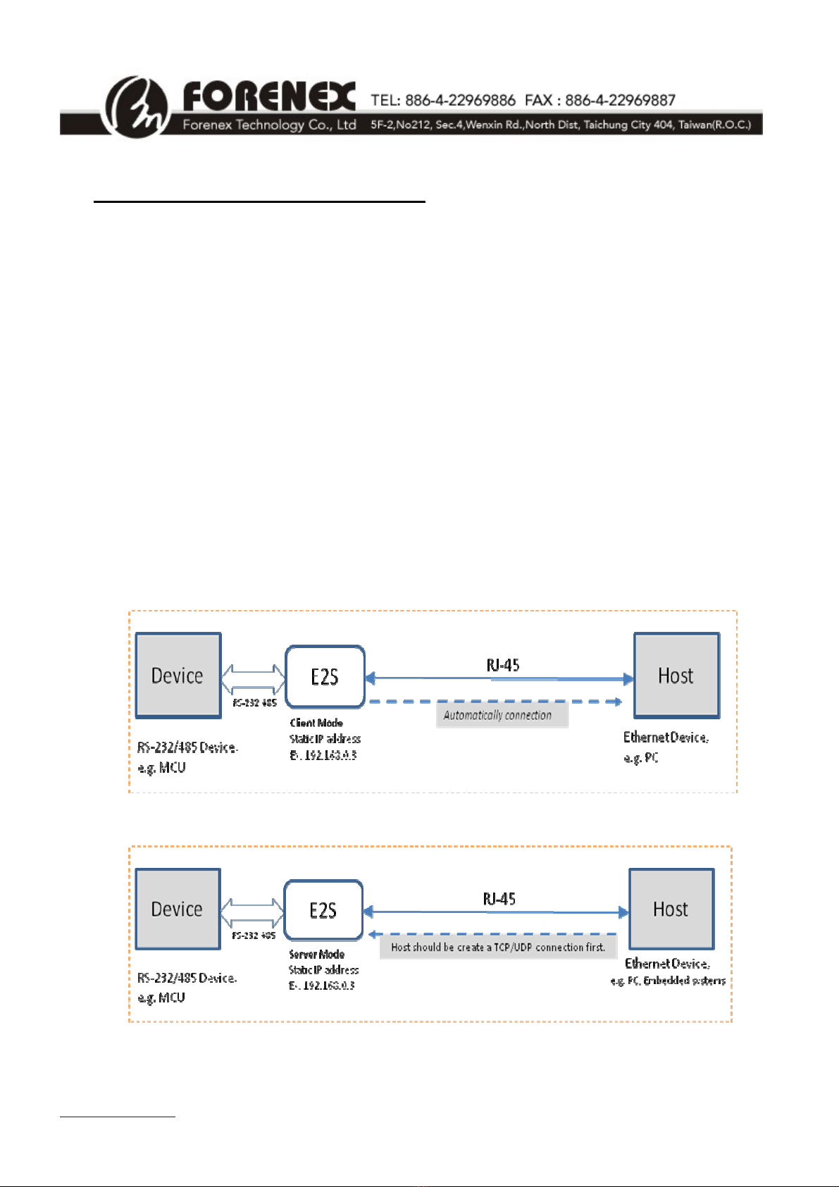
7.1) Connect to the Host via Ethernet cable directly.
a. In this case, The “DHCP client” on Web page of E2S does not recommend to be
enabled.
b. Keeping the default IP (192.168.0.3) or setting a new static IP over Web page.
c. The IP of Host and E2S should be different, but in the same IP segment.
For example: If E2S be set to 192.168.0.3, Then Host can be set to 192.168.0.xxx
(xxx is between 1 and 254, except 3).
d. When E2S is working in Client mode, the setting of “Destination Host Name/IP”
must as same as Host IP and the setting of “Destination Host Port” must as same
as listen port of Host. Then Host need to wait for the E2S to establish a TCP/UDP
connection.
e. When E2S is working in Server mode, the setting of “Listening Port” is the port
provide for Host to establish a TCP/UDP connection.
Figure 11. Working in Client Mode to connect the Host via Ethernet cable directly
Figure 12. Working in Server Mode to connect the Host via Ethernet cable directly

www.forenex.com.tw -18-
7.2) Connect to the Host via LAN.
a. Keeping the default IP (192.168.0.3) or set “DHCP client” to enable for a valid IP
asking.
b. If E2S works in Server mode and “DHCP client” is enabled, Host has to check the
IP of E2S before establish a TCP/UDP connection.
c. Following up the 7.1) c, d and e section.
Figure 13. Working in Client mode to connect the Host via LAN
Figure 14. Working in Server mode to connect the Host via LAN.
www.forenex.com.tw -19-
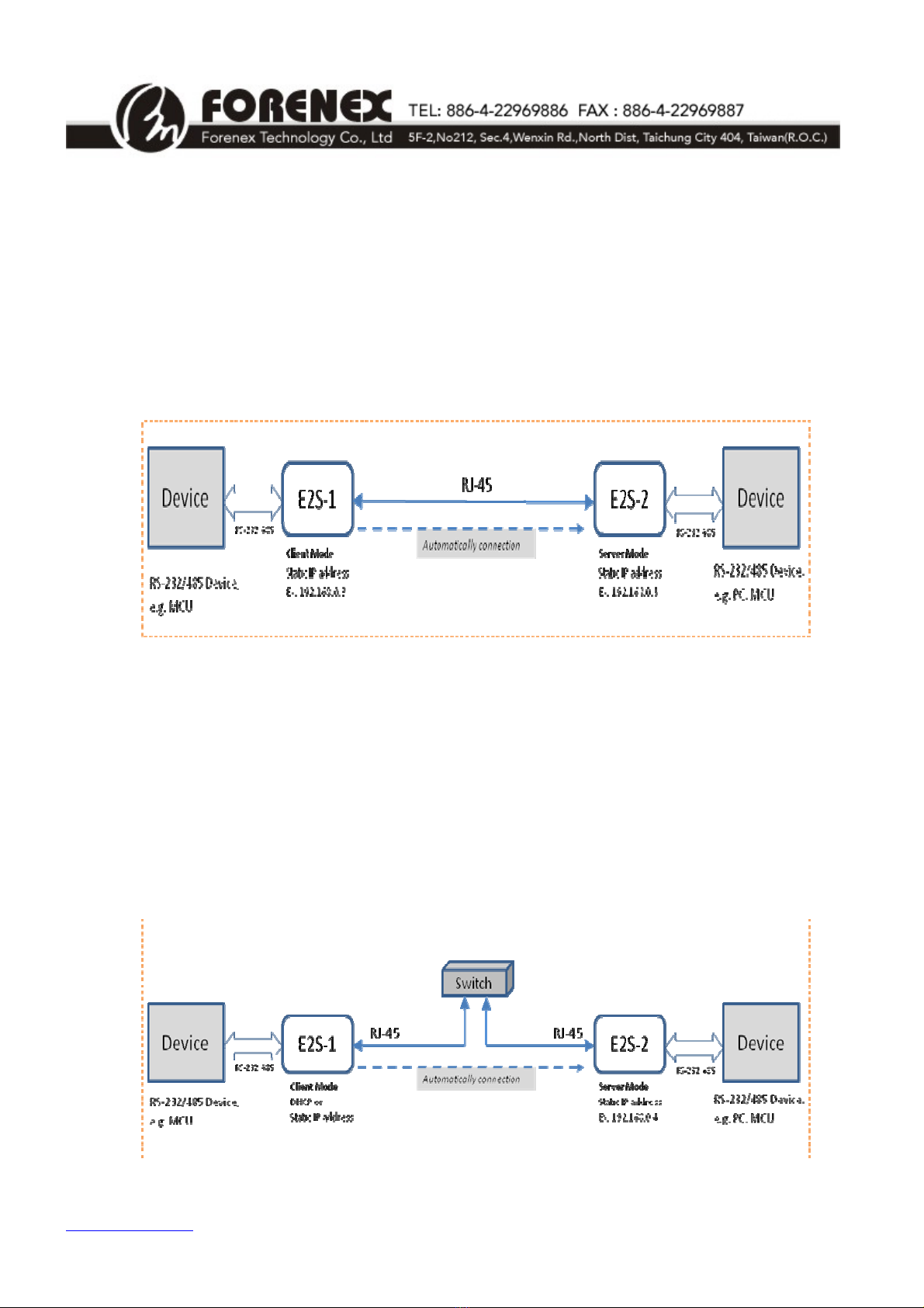
7.3) Implement existing serial communications via Ethernet cable
directly.
a. Both IP of E2S-1 and E2S-2 should be different, but in the same IP segment.
b. As shown in figure11, E2S-1 set to client mode and E2S-2 set to server mode.
c. The setting of “Listening Port” on E2S-2 and “Destination Port” on E2S-1 must be
the same.
Figure 15. Implement existing serial communications via Ethernet cable directly.
7.4) Implement existing serial communications via LAN.
a. Both IP of E2S-1 and E2S-2 should be different, but in the same IP segment.
b. As shown in figure11, E2S-1 set to client mode and E2S-2 set to server mode.
c. The setting of “Listening Port” on E2S-2 and “Destination Port” on E2S-1 must be
the same.
Figure 16. Implement existing serial communications via LAN
www.forenex.com.tw -20-
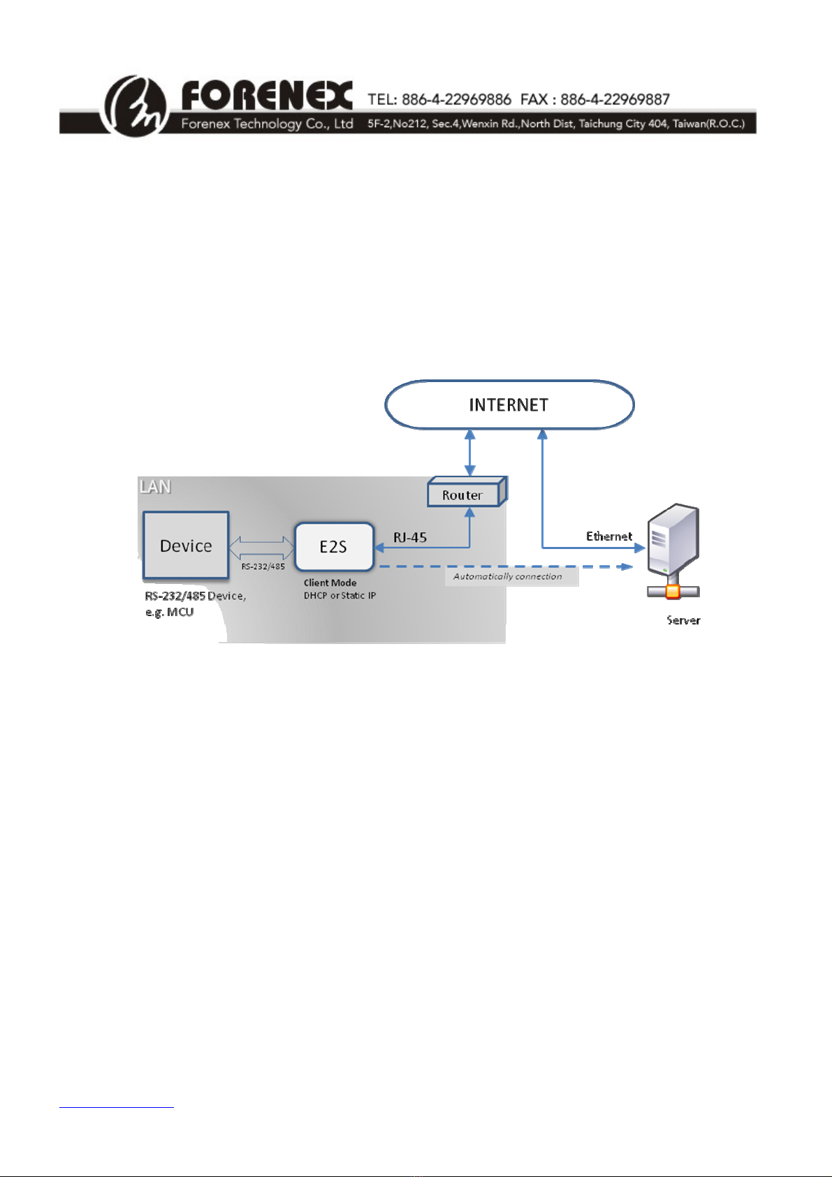
7.5) Connect to Remote Server via INTERNET.
a. In this case, the E2S can only be worked under Client mode.
b. This setting of “Destination Host Name/IP” must as same as the remote server IP
or server name.
c. Remote server need to listen the listen port of E2S for wait a TCP/UDP
connection.
Figure 17. Connect to Remote Server via INTERNET.
This manual suits for next models
2
Table of contents
Popular Adapter manuals by other brands

Maximum
Maximum 21030 user manual

Balluff
Balluff BIC 1B0-IT1A7-Q40KFU-SM4A4A installation guide

Jandy
Jandy SMARTSYNC60W Installation and operation manual

ATTO Technology
ATTO Technology Express SAS R348 specification

ZyXEL Communications
ZyXEL Communications PLA4215 quick start guide

Dormakaba
Dormakaba SLAN-DR Mounting instructions


