FORESIGHT SIM-IN-A-BOX EAGLE PLUS PACKAGE User manual

ASSEMBLY INSTRUCTIONS
Version 1.1EAGLE PLUS / BIRDIE PACKAGE

BEFORE YOU GET STARTED
ASSEMBLY INSTRUCTIONS EAGLE PLUS / BIRDIE PACKAGE VERSION 1.1
PAGE 2
THANK YOU for purchasing our SIM-IN-A-BOX package.
We're sure this package will provide you with years of enjoyment.
Before getting started with assembly, please conrm the following
to ensure your safety and those using your simulator:
Following these simple guidelines will ensure you get the most out
of your purchase, the safest way possible.
Measure and conrm you have enough space to safely install
and play. The nal setup size of your simulator will be
approximately 10 feet tall x 14 feet deep x 13 feet wide. Make
sure you have extra space for the assembly process.
Make sure you have an assistant during the assembly process.
The frame assembly requires TWO PEOPLE to safely complete.
Make sure you have all required and recommended tools to
ensure a safe assembly and setup process.

CONTENTS INSIDE THE BOX
ASSEMBLY INSTRUCTIONS EAGLE PLUS / BIRDIE PACKAGE VERSION 1.1
PAGE 3
COMPONENTS
∙(1) Frame Assembly System
∙(1) Front (Hitting) Screen
∙(1) Back Screen
∙(2) Inner Walls
∙(2) Outer Wall Covers
∙(1) Lid Panel
∙(1) Above Screen Panel
∙(1) Blackout Panel
∙(1) Rolling Computer Cart
∙(2) Rolls of Turf
∙(1) Hitting Mat and Tray System
∙ (1) Simulation Optimized PC
∙(1) Wireless Keyboard/Trackpad
∙(1) Projector with Power and HDMI Cables
∙(1) GCQuad or GC2 Launch Monitor
TOOLS
∙(1) Ratchet with 3/4” Socket
∙(1) 15 Ft Steel Fish Tape (Roll)
∙(1) Zip Ties (Bundle)
∙(1) 15’ Ratcheting Rope
∙(1) Shock Cord
REQUIRED TOOLS & ITEMS
ASSEMBLY INSTRUCTIONS EAGLE PLUS / BIRDIE PACKAGE VERSION 1.1
PAGE 4
REQUIRED TOOLS (NOT INCLUDED)
∙(2) 6-8' Ladders
RECOMMENDED TOOLS (NOT INCLUDED)
∙Impact Drill with 3/8" Impact Adapter
∙Snips for cutting Zip Ties
∙Work Gloves
∙Eye Protection Glasses

TABLE OF CONTENTS
ASSEMBLY INSTRUCTIONS EAGLE PLUS / BIRDIE PACKAGE VERSION 1.1
PAGE 5
STEP 1: FRAME ASSEMBLY
STEP 2: TURF & SCREEN
STEP 3: EXTERIOR PANELS
STEP 4: COMPONENT SETUP
STEP 5: SOFTWARE SETUP
. . . . . . . . . . . . . . . . . Page 6
. . . . . . . . . . . . . . . . . Page 20
. . . . . . . . . . . . . . . . . Page 29
. . . . . . . . . . . . . . . . Page 37
. . . . . . . . . . . . . . . . . Page 46
STEP 1: FRAME ASSEMBLY
ASSEMBLY INSTRUCTIONS EAGLE PLUS / BIRDIE PACKAGE VERSION 1.1
PAGE 6
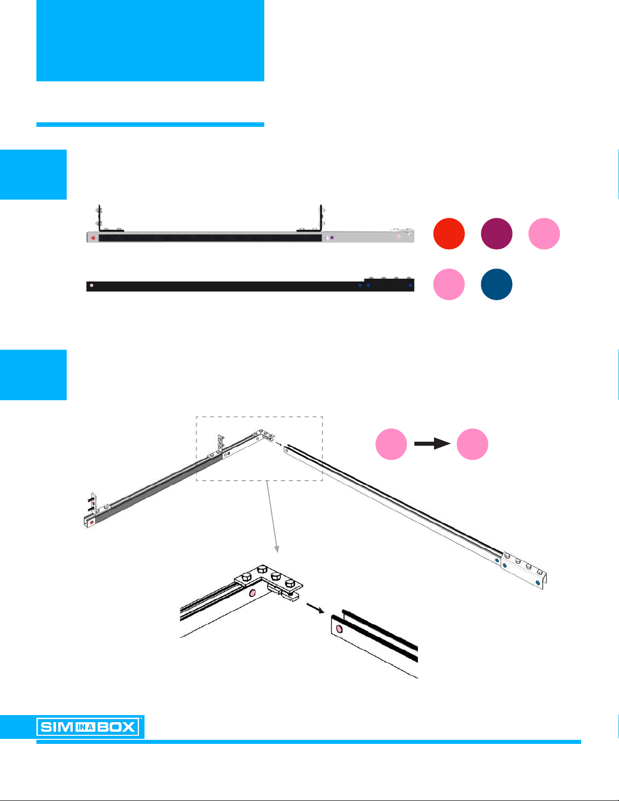
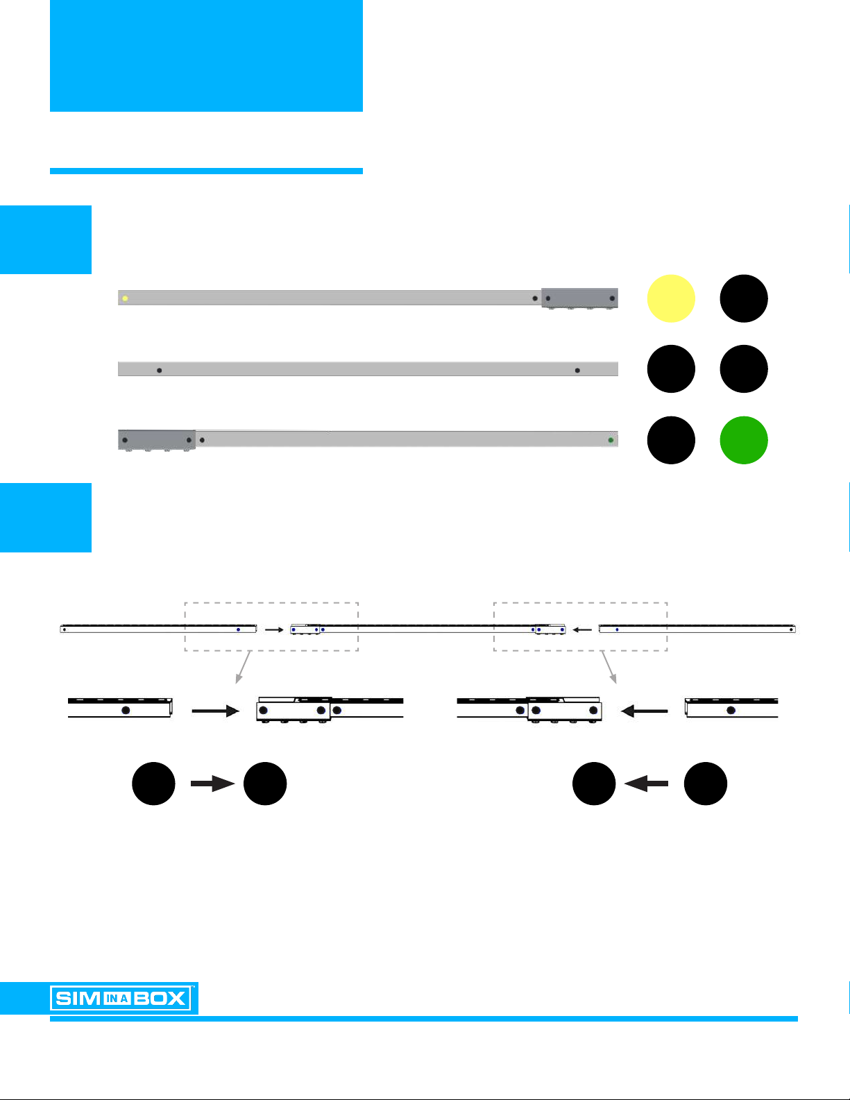
Locate the ONE (1) Left Base (Grey Fiberglass) and the ONE (1) Rear Base
Left Corner Support (Black Steel).
Connect the components at the corners marked with the PINK color code
using the bolts and nuts pre-attached to the left base.
Sim-in-a-Box Installation Guide
Step One:
Find the Red/Purple/Light Pink Left Base (Grey Fiberglass) (Horizontal) and connect to
the Light Pink/Dark Blue Rear Base Left Corner Support (Black Steel) (Horizontal).
1A
1B
Left Base
Rear Base Left Corner Support
Sim-in-a-Box Installation Guide
Step One:
Find the Red/Purple/Light Pink Left Base (Grey Fiberglass) (Horizontal) and connect to
the Light Pink/Dark Blue Rear Base Left Corner Support (Black Steel) (Horizontal).
Sim-in-a-Box Installation Guide
Step One:
Find the Red/Purple/Light Pink Left Base (Grey Fiberglass) (Horizontal) and connect to
the Light Pink/Dark Blue Rear Base Left Corner Support (Black Steel) (Horizontal).
x 1

Step Two:
Connect the Light Pink/Dark Blue Rear Base Left Corner Support (Black Steel - No
Velcro) (Horizontal) to the Dark Blue/Dark Blue Rear Base Middle Support (Black Steel -
No Velcro) (Horizontal).
STEP 1: FRAME ASSEMBLY
ASSEMBLY INSTRUCTIONS EAGLE PLUS / BIRDIE PACKAGE VERSION 1.1
PAGE 7
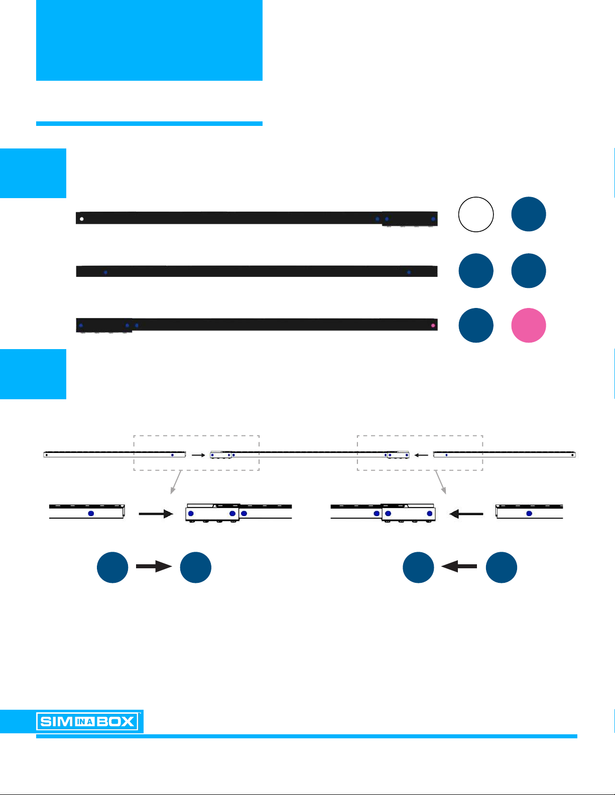
Locate the ONE (1) Rear Base Middle Support (Black Steel / No Velcro)
Connect to the step 1 assembly at the corners marked with the DARK BLUE color code
using the bolts and nuts pre-attached to the Rear Base Left Corner Support.
2A
2B
Rear Base Middle Suppprt
Step Two:
Connect the Light Pink/Dark Blue Rear Base Left Corner Support (Black Steel - No
Velcro) (Horizontal) to the Dark Blue/Dark Blue Rear Base Middle Support (Black Steel -
No Velcro) (Horizontal).
Step Two:
Connect the Light Pink/Dark Blue Rear Base Left Corner Support (Black Steel - No
Velcro) (Horizontal) to the Dark Blue/Dark Blue Rear Base Middle Support (Black Steel -
No Velcro) (Horizontal).
x 1

Step Three:
Connect the Dark Blue/Dark Blue Rear Base Middle Support (Black Steel - No Velcro)
(Horizontal) to the Dark Blue/Tan Rear Base Right Corner Support (Black Steel - No
Velcro) (Horizontal).
STEP 1: FRAME ASSEMBLY
ASSEMBLY INSTRUCTIONS EAGLE PLUS / BIRDIE PACKAGE VERSION 1.1
PAGE 8
Locate the ONE (1) Rear Base Right Corner Support (Black Steel / No Velcro)
Connect to the step 2 assembly at the corners marked with the DARK BLUE color code
using the bolts and nuts pre-attached to the Base Right Corner Support.
3A
3B
Rear Base Right Corner Support
Step Two:
Connect the Light Pink/Dark Blue Rear Base Left Corner Support (Black Steel - No
Velcro) (Horizontal) to the Dark Blue/Dark Blue Rear Base Middle Support (Black Steel -
No Velcro) (Horizontal).
Step Two:
Connect the Light Pink/Dark Blue Rear Base Left Corner Support (Black Steel - No
Velcro) (Horizontal) to the Dark Blue/Dark Blue Rear Base Middle Support (Black Steel -
No Velcro) (Horizontal).
x 1

Step Four:
Connect the Dark Blue/Tan Rear Base Right Corner Support (Black Steel - No Velcro)
(Horizontal) to the Red/Purple/Tan Right Base (Grey Fiberglass) (Horizontal).
STEP 1: FRAME ASSEMBLY
ASSEMBLY INSTRUCTIONS EAGLE PLUS / BIRDIE PACKAGE VERSION 1.1
PAGE 9
Locate the ONE (1) Right Base (Grey Fiberglass).
Connect to the step 3 assembly at the corners marked with the TAN color code
using the bolts and nuts pre-attached to the Right Base.
4A
4B
Right Base
Step Four:
Connect the Dark Blue/Tan Rear Base Right Corner Support (Black Steel - No Velcro)
(Horizontal) to the Red/Purple/Tan Right Base (Grey Fiberglass) (Horizontal).
Step Four:
Connect the Dark Blue/Tan Rear Base Right Corner Support (Black Steel - No Velcro)
(Horizontal) to the Red/Purple/Tan Right Base (Grey Fiberglass) (Horizontal).
x 1

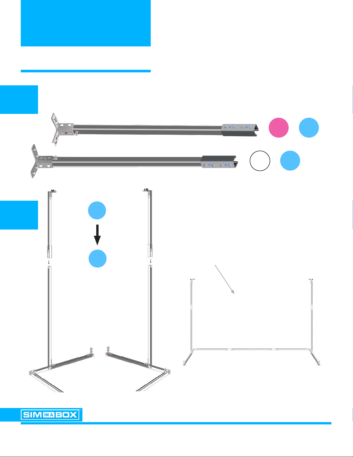
Step Five:
Connect One Purple/Light Blue Rear Right Side Wall Bottom Support (Grey Fiberglass)
(Vertical) to the Red/Purple/Tan Right Base (Grey Fiberglass) (Horizontal).
Then, connect One Purple/Light Blue Rear Left Side Wall Bottom Support (Grey
Fiberglass) (Vertical) to the Red/Purple/Light Pink Left Base (Grey Fiberglass)
(Horizontal).
STEP 1: FRAME ASSEMBLY
ASSEMBLY INSTRUCTIONS EAGLE PLUS / BIRDIE PACKAGE VERSION 1.1
PAGE 10
Locate the TWO (2) Rear Side Wall Bottom Supports (Grey Fiberglass).
Note: Velcro LOOP on the outside edge, velcro HOOK on the back edge.
Connect to the step 4 assembly
at the corners marked with the
PURPLE color code
using the bolts and nuts
pre-attached to the Left Base
and Right Base.
5A
5B
Rear Side Wall Bottom Supports (x2)
Step Five:
Connect One Purple/Light Blue Rear Right Side Wall Bottom Support (Grey Fiberglass)
(Vertical) to the Red/Purple/Tan Right Base (Grey Fiberglass) (Horizontal).
Then, connect One Purple/Light Blue Rear Left Side Wall Bottom Support (Grey
Fiberglass) (Vertical) to the Red/Purple/Light Pink Left Base (Grey Fiberglass)
(Horizontal).
x 2

STEP 1: FRAME ASSEMBLY
ASSEMBLY INSTRUCTIONS EAGLE PLUS / BIRDIE PACKAGE VERSION 1.1
PAGE 11
The frame assembly should now look like this:
Step Five:
Connect One Purple/Light Blue Rear Right Side Wall Bottom Support (Grey Fiberglass)
(Vertical) to the Red/Purple/Tan Right Base (Grey Fiberglass) (Horizontal).
Then, connect One Purple/Light Blue Rear Left Side Wall Bottom Support (Grey
Fiberglass) (Vertical) to the Red/Purple/Light Pink Left Base (Grey Fiberglass)
(Horizontal).
STEP 1: FRAME ASSEMBLY
ASSEMBLY INSTRUCTIONS EAGLE PLUS / BIRDIE PACKAGE VERSION 1.1
PAGE 12
Locate the TWO (2) Rear Side Wall Top Supports (Grey Fiberglass).
6A
6B
Step Six:
Connect the Pink/Light Blue Rear Right Side Wall Top Support (Grey Fiberglass)
(Vertical) to the Purple/Light Blue Rear Right Side Wall Bottom Support (Grey
Fiberglass) (Vertical).
Then, connect the White/Light Blue Rear Left Side Wall Top Support (Grey Fiberglass)
(Vertical) to the Purple/Light Blue Rear Left Side Wall Bottom Support (Grey Fiberglass)
(Vertical).
Rear RIGHT SIDE Wall Top Supports
Rear LEFT SIDE Wall Top Supports
Connect to the step 5 assembly at the Rear
Side Wall Bottom Supports marked with the
LIGHT BLUE color code using the bolts and
nuts pre-attached to the Wall Top Supports
When nished, the assembly should
look like this
Step Five:
Connect One Purple/Light Blue Rear Right Side Wall Bottom Support (Grey Fiberglass)
(Vertical) to the Red/Purple/Tan Right Base (Grey Fiberglass) (Horizontal).
Then, connect One Purple/Light Blue Rear Left Side Wall Bottom Support (Grey
Fiberglass) (Vertical) to the Red/Purple/Light Pink Left Base (Grey Fiberglass)
(Horizontal).
x 2
Step Seven:
Connect the White/Dark Blue Rear Top Frame Left Corner Support (Black Steel - With
Velcro) (Horizontal) to the Dark Blue/Dark Blue Rear Top Frame Middle Support (Black
Steel - With Velcro) (Horizontal).
Then, connect the Dark Blue/Dark Blue Rear Top Frame Middle Support (Black Steel -
With Velcro) (Horizontal) to the Dark Blue/Pink Rear Top Frame Right Corner Support
(Black Steel - With Velcro) (Horizontal).
STEP 1: FRAME ASSEMBLY
ASSEMBLY INSTRUCTIONS EAGLE PLUS / BIRDIE PACKAGE VERSION 1.1
PAGE 13
Locate the THREE (3) Rear Top Frame Support components (Black Steel with Velcro).
Connect the Rear Top Frame Support components as illustrated
using the pre-attached bolts and nuts.
7A
7B
Rear Top Frame LEFT CORNER Support
Rear Top Frame MIDDLE Support
Rear Top Frame RIGHT CORNER Support
Step Two:
Connect the Light Pink/Dark Blue Rear Base Left Corner Support (Black Steel - No
Velcro) (Horizontal) to the Dark Blue/Dark Blue Rear Base Middle Support (Black Steel -
No Velcro) (Horizontal).
Step Two:
Connect the Light Pink/Dark Blue Rear Base Left Corner Support (Black Steel - No
Velcro) (Horizontal) to the Dark Blue/Dark Blue Rear Base Middle Support (Black Steel -
No Velcro) (Horizontal).
Step Two:
Connect the Light Pink/Dark Blue Rear Base Left Corner Support (Black Steel - No
Velcro) (Horizontal) to the Dark Blue/Dark Blue Rear Base Middle Support (Black Steel -
No Velcro) (Horizontal).
Step Two:
Connect the Light Pink/Dark Blue Rear Base Left Corner Support (Black Steel - No
Velcro) (Horizontal) to the Dark Blue/Dark Blue Rear Base Middle Support (Black Steel -
No Velcro) (Horizontal).

STEP 1: FRAME ASSEMBLY
ASSEMBLY INSTRUCTIONS EAGLE PLUS / BIRDIE PACKAGE VERSION 1.1
PAGE 14
Attach the assembled Rear Top Frame Support to the main assembly
as illustrated using the pre-attached bolts and nuts.
8
REQUIRED FOR THIS STEP
X2
Sim-in-a-Box Installation Guide
Step One:
Find the Red/Purple/Light Pink Left Base (Grey Fiberglass) (Horizontal) and connect to
the Light Pink/Dark Blue Rear Base Left Corner Support (Black Steel) (Horizontal).
Sim-in-a-Box Installation Guide
Step One:
Find the Red/Purple/Light Pink Left Base (Grey Fiberglass) (Horizontal) and connect to
the Light Pink/Dark Blue Rear Base Left Corner Support (Black Steel) (Horizontal).
Step Seven:
Connect the White/Dark Blue Rear Top Frame Left Corner Support (Black Steel - With
Velcro) (Horizontal) to the Dark Blue/Dark Blue Rear Top Frame Middle Support (Black
Steel - With Velcro) (Horizontal).
Then, connect the Dark Blue/Dark Blue Rear Top Frame Middle Support (Black Steel -
With Velcro) (Horizontal) to the Dark Blue/Pink Rear Top Frame Right Corner Support
(Black Steel - With Velcro) (Horizontal).

Step Nine:
Connect the White/Yellow Left Top Side Frame Support (Grey Fiberglass) (Horizontal) to
the White/Light Blue Rear Left Side Wall Top Support (Grey Fiberglass) (Vertical).
Then, connect the Pink/Green Right Top Side Frame Support (Grey Fiberglass)
(Horizontal) to the Pink/Light Blue Rear Right Side Wall Top Support (Grey Fiberglass)
(Vertical).
STEP 1: FRAME ASSEMBLY
ASSEMBLY INSTRUCTIONS EAGLE PLUS / BIRDIE PACKAGE VERSION 1.1
PAGE 15
Locate the TWO (2) Top Side Frame Supports (Grey Fiberglass).
9A
9B Connect the Top Side Frame Supports as illustrated using the
pre-attached bolts and nuts.
Step Nine:
Connect the White/Yellow Left Top Side Frame Support (Grey Fiberglass) (Horizontal) to
the White/Light Blue Rear Left Side Wall Top Support (Grey Fiberglass) (Vertical).
Then, connect the Pink/Green Right Top Side Frame Support (Grey Fiberglass)
(Horizontal) to the Pink/Light Blue Rear Right Side Wall Top Support (Grey Fiberglass)
(Vertical).
LEFT Top Side Frame Support
RIGHT Top Side Frame Support
REQUIRED FOR THIS STEP
X1
Step Seven:
Connect the White/Dark Blue Rear Top Frame Left Corner Support (Black Steel - With
Velcro) (Horizontal) to the Dark Blue/Dark Blue Rear Top Frame Middle Support (Black
Steel - With Velcro) (Horizontal).
Then, connect the Dark Blue/Dark Blue Rear Top Frame Middle Support (Black Steel -
With Velcro) (Horizontal) to the Dark Blue/Pink Rear Top Frame Right Corner Support
(Black Steel - With Velcro) (Horizontal).
Sim-in-a-Box Installation Guide
Step One:
Find the Red/Purple/Light Pink Left Base (Grey Fiberglass) (Horizontal) and connect to
the Light Pink/Dark Blue Rear Base Left Corner Support (Black Steel) (Horizontal).
Sim-in-a-Box Installation Guide
Step One:
Find the Red/Purple/Light Pink Left Base (Grey Fiberglass) (Horizontal) and connect to
the Light Pink/Dark Blue Rear Base Left Corner Support (Black Steel) (Horizontal).

STEP 1: FRAME ASSEMBLY
ASSEMBLY INSTRUCTIONS EAGLE PLUS / BIRDIE PACKAGE VERSION 1.1
PAGE 16
Locate the TWO (2) Side Wall Bottom Supports (Grey Fiberglass).
Note: Velcro HOOK on the outside edge.
10A
10B Connect ONE (1) Side Wall Bottom Support to the Left Base and ONE (1) Side Wall
Bottom Support to the Right Base as illustrated using the pre-attached bolts and nuts.
REQUIRED FOR THIS STEP
X1
Step Ten:
Connect One Red/Light Blue Front Right Side Wall Bottom Support (Grey Fiberglass)
(Vertical) to the Red/Purple/Tan Right Base (Grey Fiberglass) (Horizontal).
Then, connect One Red/Light Blue Front Left Side Wall Bottom Support (Grey
Fiberglass) (Vertical) to the Red/Purple/Light Pink Left Base (Grey Fiberglass)
(Horizontal).

STEP 1: FRAME ASSEMBLY
ASSEMBLY INSTRUCTIONS EAGLE PLUS / BIRDIE PACKAGE VERSION 1.1
PAGE 17
Locate the TWO (2) Side Wall Top Supports (Grey Fiberglass).
11A
11B Connect the Top Side Wall Supports as illustrated in the noted order using
the pre-attached bolts and nuts.
REQUIRED FOR THIS STEP
X1
Step Eleven:
Connect the Yellow/Light Blue Front Left Side Wall Top Support (Grey Fiberglass)
(Vertical) to the Red/Light Blue Front Left Side Wall Bottom Support (Grey Fiberglass)
(Vertical).
Then, connect the White/Yellow Left Top Side Frame Support (Grey Fiberglass)
(Horizontal) to the Yellow/Light Blue Front Left Side Wall Top Support (Grey Fiberglass)
(Vertical).
Connect the Green/Light Blue Front Right Side Wall Top Support (Grey Fiberglass)
(Vertical) to the Red/Light Blue Front Right Side Wall Bottom Support (Grey Fiberglass)
(Vertical).
Then, connect the Pink/Green Right Top Side Frame Support (Grey Fiberglass)
(Horizontal) to the Green/Light Blue Front Right Side Wall Top Support (Grey Fiberglass)
(Vertical).
Step Six:
Connect the Pink/Light Blue Rear Right Side Wall Top Support (Grey Fiberglass)
(Vertical) to the Purple/Light Blue Rear Right Side Wall Bottom Support (Grey
Fiberglass) (Vertical).
Then, connect the White/Light Blue Rear Left Side Wall Top Support (Grey Fiberglass)
(Vertical) to the Purple/Light Blue Rear Left Side Wall Bottom Support (Grey Fiberglass)
(Vertical).
Front LEFT SIDE Wall Top Supports
Front RIGHT SIDE Wall Top Supports
Step Five:
Connect One Purple/Light Blue Rear Right Side Wall Bottom Support (Grey Fiberglass)
(Vertical) to the Red/Purple/Tan Right Base (Grey Fiberglass) (Horizontal).
Then, connect One Purple/Light Blue Rear Left Side Wall Bottom Support (Grey
Fiberglass) (Vertical) to the Red/Purple/Light Pink Left Base (Grey Fiberglass)
(Horizontal).
CONNECT
FIRST
CONNECT
FIRST
CONNECT
SECOND
CONNECT
SECOND
Step Twelve:
Connect the Yellow/Black Front Top Frame Left Corner Support (Grey Fiberglass)
(Horizontal) to the Black/Black Front Top Frame Middle Support (Grey Fiberglass)
(Horizontal).
Then, connect the Black/Black Front Top Frame Middle Support (Grey Fiberglass)
(Horizontal) to the Black/Green Front Top Frame Right Corner Support (Grey Fiberglass)
(Horizontal).
STEP 1: FRAME ASSEMBLY
ASSEMBLY INSTRUCTIONS EAGLE PLUS / BIRDIE PACKAGE VERSION 1.1
PAGE 18
Locate the THREE (3) Front Top Frame Support components (Black Steel with Velcro).
Connect the Front Top Frame Support components as illustrated
using the pre-attached bolts and nuts.
12A
12B
Front Top Frame LEFT CORNER Support
Front Top Frame MIDDLE Support
Front Top Frame RIGHT CORNER Support
Step Twelve:
Connect the Yellow/Black Front Top Frame Left Corner Support (Grey Fiberglass)
(Horizontal) to the Black/Black Front Top Frame Middle Support (Grey Fiberglass)
(Horizontal).
Then, connect the Black/Black Front Top Frame Middle Support (Grey Fiberglass)
(Horizontal) to the Black/Green Front Top Frame Right Corner Support (Grey Fiberglass)
(Horizontal).

STEP 1: FRAME ASSEMBLY
ASSEMBLY INSTRUCTIONS EAGLE PLUS / BIRDIE PACKAGE VERSION 1.1
PAGE 19
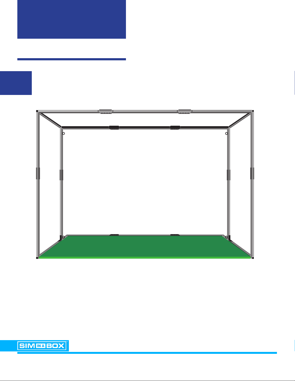
Attach the assembled Front Top Frame Support to the main assembly
as illustrated using the pre-attached bolts and nuts.
13
REQUIRED FOR THIS STEP
DOUBLE-CHECK!
With the frame now assembled, please re-check that
all assembly bolts are tight and the frame is stable and rigid.
X2
Step Eleven:
Connect the Yellow/Light Blue Front Left Side Wall Top Support (Grey Fiberglass)
(Vertical) to the Red/Light Blue Front Left Side Wall Bottom Support (Grey Fiberglass)
(Vertical).
Then, connect the White/Yellow Left Top Side Frame Support (Grey Fiberglass)
(Horizontal) to the Yellow/Light Blue Front Left Side Wall Top Support (Grey Fiberglass)
(Vertical).
Connect the Green/Light Blue Front Right Side Wall Top Support (Grey Fiberglass)
(Vertical) to the Red/Light Blue Front Right Side Wall Bottom Support (Grey Fiberglass)
(Vertical).
Then, connect the Pink/Green Right Top Side Frame Support (Grey Fiberglass)
(Horizontal) to the Green/Light Blue Front Right Side Wall Top Support (Grey Fiberglass)
(Vertical).
STEP 2: TURF & SCREEN
ASSEMBLY INSTRUCTIONS EAGLE PLUS / BIRDIE PACKAGE VERSION 1.1
PAGE 20
Locate the Interior Turf Roll and place it inside the assembled frame.
NOTE: Make sure the assembled frame and interior turf are in their nal playing position.
1
This manual suits for next models
1
Table of contents
Other FORESIGHT Video Gaming Accessories manuals


Popular Video Gaming Accessories manuals by other brands


Conspit
Conspit GT-lite quick guide

Mightymast Leisure
Mightymast Leisure PARTY Assembly instructions

Elgato
Elgato Game Capture HD60 Pro Manual and user guide

Radica Games
Radica Games Play TV Huntin' 3 instruction manual

JT
JT ER2 Operator's manual

Granite Devices
Granite Devices Simucube 2 Accessory port Application guide

UNEEKOR
UNEEKOR EYE XO2 installation guide

DreamGEAR
DreamGEAR Gold Edition Quick Shot PLUS DGWII-1284 user guide

Sveaverken
Sveaverken F100 Software user manual

Costco
Costco Arlington Assembly And Instructions

Textron
Textron Saitek Pro Flight Cessna Yoke System manual

5DT
5DT Data Glove Ultra Series user manual