Formica Intentek Quick start guide

1INTENTEK™WIRELESS CHARGING SURFACES BY FORMICA GROUP
TECHNICAL GUIDE, USE & CARE, WARRANTY, AND INSTALLATION GUIDE
TABLE OF CONTENTS
Use and Care / Safety .......................................................................................................................... 2
Introduction: ............................................................................................................................................ 2
Intentek™System Componentry Provided by Formica Group:.................................................................. 2
What is Wireless Charging:...................................................................................................................... 3
WPC, Qi and Qi Certication:................................................................................................................... 4
Incorporation of Intentek™Wireless Charging Surfaces into Furniture Design: Tips & Best Practices ....... 4
To Order: ................................................................................................................................................. 5
General Safety:........................................................................................................................................ 5
Customer Safety:..................................................................................................................................... 5
Customer Use & Care after Installation:.................................................................................................... 5
Scratch and Impact Protection of the Decorative Surface: ....................................................................... 5
Hot Objects: ............................................................................................................................................ 5
Ordinary Cleaning of the Decorative Surface:........................................................................................... 6
Ordinary Cleaning of Underside of Table/Counter:.................................................................................... 6
Fabrication & Installation..................................................................................................................... 7
Fabrication & Installation Related Safety:.................................................................................................. 7
Inspection:............................................................................................................................................... 7
Storage Conditions:................................................................................................................................. 7
Acclimation Conditions: ........................................................................................................................... 7
Fabrication Conditions:............................................................................................................................ 7
Intentek™ Wireless Charging Surfaces May Be Applied To: ..................................................................... 7
Tools & Materials Sold by Formica Group:................................................................................................ 8
Additional Tools & Materials Needed:....................................................................................................... 8
Approved Adhesives:............................................................................................................................... 8
Important Installation Tips & Reminders:.................................................................................................. 9
Basic Installation Steps for Panel Lay-up and CNC Fabrication:............................................................. 10
1. PANEL LAYUP............................................................................................................................. 10
2. PRE-PRODUCTION – Engineering and CNC Operations ............................................................. 11
3. PRODUCTION - CNC Operations (Typical steps) ......................................................................... 12
4. PRODUCTION............................................................................................................................. 15
5. ELECTRONICS INSTALLATION ................................................................................................... 15
6. FINISH ASSEMBLY...................................................................................................................... 21
Connecting Multiple Electronics Modules to a Single AC Adapter: ......................................................... 17
Quality Check - Conrmation of Successful Installation: ......................................................................... 22
Troubleshooting:.................................................................................................................................... 22
Electronics Module Unit Replacement:................................................................................................... 22

INTENTEK™WIRELESS CHARGING SURFACES BY FORMICA GROUP
TECHNICAL GUIDE, USE & CARE, WARRANTY, AND INSTALLATION GUIDE
2
Physical Properties Backer .............................................................................................................. 22
Physical Properties Laminate............................................................................................................ 23
Electronics Specications and Compliance ................................................................................... 24
Lifetime Expectancy Testing: ............................................................................................................ 25
FCC Compliance Statement:............................................................................................................. 25
UL Standards: ..................................................................................................................................... 26
LEGAL TERMS AND CONDITIONS OF USE ..................................................................................... 26
Warranty .............................................................................................................................................. 26
Intentek™Wireless Charging Surfaces Limited Warranty: ....................................................................... 26
Other Information: .............................................................................................................................. 29
Manufacturer: ........................................................................................................................................ 29
Electronics Disposal: ............................................................................................................................. 29
Technical Services: ................................................................................................................................ 29
Trademarks: .......................................................................................................................................... 29
Charging Surface
Smartphone
Receiver in Smartphone
Magnetic field
Electronics
Module
Decorative Laminate
Electrical Coil Array
Substrate
Substrate
Backer
Backer
Transmitter in
Intentek™Laminate
Use Care & Safety
Introduction
Intentek™Wireless Charging Surfaces feature integrated phone charging technology within the decorative
laminate surface for a beautiful, seamless, clutter-free design and superior user experience.
• Embedded technology for an uninterrupted surface
• Fast charge times that rival cord charging
• Large 2”x2” charging zone for a simple drop and charge user experience
• Qi Certied for safe, reliable wireless power transfer and device protection
• Works with all Qi certied devices
• Durable laminate surface
• Easy to clean and maintain
• Full range of Formica®Brand Laminate designs
Intentek™ System Componentry Provided by Formica Group:
• Intentek™ Laminate
• Intentek™ Laminate backer
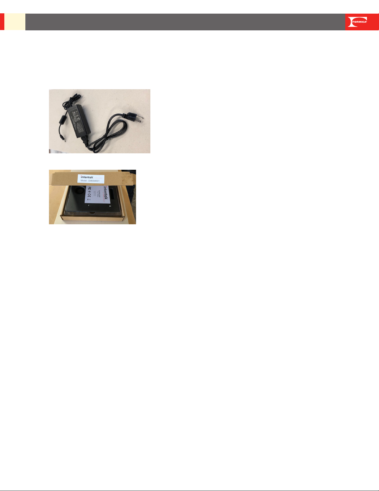
• Intentek™ Electronics universal AC power adapter
• Intentek™ Electronics Module
3INTENTEK™WIRELESS CHARGING SURFACES BY FORMICA GROUP
TECHNICAL GUIDE, USE & CARE, WARRANTY, AND INSTALLATION GUIDE
What is Wireless Charging:
Wireless charging, also known as wireless power transfer, provides the ability to charge a device without
charging cables. The Intentek™ System uses the Qi wireless charging standard which provides safe and
reliable wireless power transfer. The power is transferred from the Qi wireless transmitter to the Qi wireless
receiver via magnetic resonant induction.
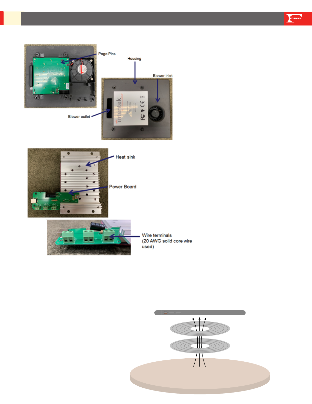
The magnetic eld is generated in the transmitter
coils by a time-varying electric current.
This time-varying magnetic eld generates an
alternating electric current in the receiver coil
which is rectied and used to charge the battery.
The diagram below demonstrates this concept.
Charging Surface
Smartphone
Receiver in Smartphone
Magnetic field
Electronics
Module
Decorative Laminate Electrical Coil Array
Substrate
Substrate
Backer
Backer
Transmitter in
Intentek™Laminate
Electronics Module Parts:

INTENTEK™WIRELESS CHARGING SURFACES BY FORMICA GROUP
TECHNICAL GUIDE, USE & CARE, WARRANTY, AND INSTALLATION GUIDE
4
WPC, Qi and Qi Certication:
Qi (pronounced “chee”) is the predominant standard for wireless charging. The standard is governed
by the Wireless Power Consortium (WPC) which has more than 575 member companies. To date,
more than 500 million Qi enabled receivers have been shipped.
Qi Certied products have passed rigorous, independent laboratory tests for safety, interoperability,
energy eciency and quality. To be certied, they must work with all Qi wireless products regardless
of brand or manufacturer. Qi certication ensures that devices (the power receivers) and chargers
(the power transmitters) always work together for simple and easy charging.
Incorporation of Intentek™Wireless Charging Surfaces into Furniture Design:
Tips & Best Practices
Location of the charging zones will vary from project to project. The following points represent tips
and best practices that should be considered for placement of the charging zones only. Formica
Group is not responsible and assumes no liability for the design, engineering, installation, assembly
or structural integrity of the fabricated piece.
• Cavity for electronics module must be at least 1” from all edges of table/top.
• Blower direction can point up, down, left, or right (at 90, 180, 270, 360 degrees).
• Blower inlet and outlet cannot be covered by pedestal, leg, or other obstruction.
• When placing charging zones near each other, we recommend at least 11” is left between
center points of the charging icons. The electronic module casing must be at least 1” apart.
• When placing two electronics modules near each other, a blower inlet must be at least 8”
from another blower’s outlet. This rule is to be followed only if blower inlet and outlet are
designed to be near each other.
• If Intentek™System is going to be used in an enclosed counter (i.e. on top of a cabinet or
drawer), the enclosed space must be properly vented. Vent determination is the responsibility
of the furniture designer. Venting must be sucient to support the blower at 2CFM.
• Electronics module cannot be in direct contact with obstructions: edges, screws, pedestals/
legs.
4
This is the outlet.
This is the inlet.

5INTENTEK™WIRELESS CHARGING SURFACES BY FORMICA GROUP
TECHNICAL GUIDE, USE & CARE, WARRANTY, AND INSTALLATION GUIDE
To Order:
Call 1-800-FORMICA™ or visit here: https://www.formica.com/en-us/campaigns/intentek/intentek-inquiry-form
General Safety:
Please read this Technical Guide, Use & Care, Warranty, and Installation Guide and all warnings
contained herein prior to handling the Intentek™System.
Customer Safety:
1. For indoor use only.
2. Do not overload electrical outlets.
3. AC Adapter must be plugged into a compatible mains supply to operate.
4. Intentek™ Electronics AC Adapter or equivalent must be used.
5. Never use the AC Adapter if damaged in any way.
6. When using the AC Adapter or extension cord, conrm safety precautions have been made so
there are no tripping hazards.
7. Keep any wiring used to connect Electronics Modules covered.
Customer Use & Care after Installation:
1. Do not unscrew the electronics module housing without professional support.
If internal parts are ever exposed, avoid contact with sharp objects and moisture.
2. May not be housed outside of recommended temperature range.
3. May not be stored outdoors.
4. At all times, keep electronics module and AC adapter away from liquids.
5. Do not place foreign or sharp objects in the electronics module or blower inlet / outlet.
6. Follow all cleaning instructions for decorative surface. Do not attempt to clean inside of
electronics module.
Scratch and Impact Protection of the Decorative Surface:
The decorative surface is resistant to scratches and impacts under normal use and cleaning conditions.
However:
• Heavy blows may crack or gouge the surface.
• Sharp or abrasive objects and unglazed ceramics materials may slice, scratch or cause premature wear
on the surface.
• Abrasive pads, scouring powders or cleaners may permanently dull and scratch the decorative surface.
Hot Objects:
Hot objects, such as cookware, irons, hot appliances, cigarettes, etc. should not be placed directly on dec-
orative surfaces. Use a trivet, insulated hot pad or other protective device beneath all hot cookware, heat
generated appliances or other heated objects.
Prolonged exposure to temperatures of 140 degrees F (60C) or higher may cause the laminate to
separate from the core material. Intentek™Laminate surfacing material can withstand heat up to
275 degrees F (135C) for short periods of time.

INTENTEK™WIRELESS CHARGING SURFACES BY FORMICA GROUP
TECHNICAL GUIDE, USE & CARE, WARRANTY, AND INSTALLATION GUIDE
6
Ordinary Cleaning of the Decorative Surface:
Decorative surface may be cleaned with a damp cloth and mild detergent. Use of abrasive cleaners,
powders, scouring pads, steel wool, or sandpaper can damage the nish of the decorative surface.
Acid, sodium hypochlorite or alkaline-based cleaners and/or compounds will mar, etch, corrode, and
permanently discolor the melamine decorative surface.
Do not use these cleaning materials on decorative laminate, nor allow bottles and/or rags contaminat-
ed with acid or alkaline–based cleaners/compounds to contact the surface. Accidental spills or splat-
ters from these harsh materials should be wiped o immediately, and the area cleaned with a damp
cloth.
Examples of cleaners containing acid, alkali, or sodium hypochlorite include, but are not limited to:
• ceramic cooktop cleaners
• oven cleaners
• chlorine bleach
• rust removers
• coeepot cleaners
• some countertop cleaners, Clorox® Clean-Up® Cleaner + Bleach
• drain cleaners
• some disinfectants, such as Clorox® Germicidal Bleach
• lime scale removers
• toilet bowl cleaners
• metal cleaners
• tub and tile cleaners
If in doubt about the suitability of a particular cleaner or detergent, check with its manufacturer.
Additional Special Cleaning information can be found in the Formica®Brand Laminate Use and
Care Guide available https://www.formica.com/en-us/-/media/formica/north-america/docu-
ment-library/warranty/laminate_colorecore2_compact-use-and-care-guide.pdf?la=en-us&rev=ab-
da37e54d894b25921393cdb8691cc1
Ordinary Cleaning of Underside of Table/Counter:
Should cleaning on the underside of the counter/table be needed, avoid exposing the electronics
to any liquids.

7INTENTEK™WIRELESS CHARGING SURFACES BY FORMICA GROUP
TECHNICAL GUIDE, USE & CARE, WARRANTY, AND INSTALLATION GUIDE
Fabrication & Installation
Fabrication & Installation Related Safety:
1. All points in Customer Safety above also pertain to fabrication and installation safety.
2. Fabricators and installers must follow all OSHA/ National Electric Code /UL Standards as
required by installation location or customer.
3. Do not power the electronics until fully assembled into a table or top. Make all connections to
the Intentek™Electronics Module before applying power.
8. Intentek™ Electronics AC Adapter or equivalent must be used. Formica Group does not
recommend or warranty hardwiring.
4. Do not install nished table or top while electronics are powered.
5. Always use recommended wire to connect electronics modules.
6. Always cover wiring underneath table/counter.
Inspection:
Inspect all materials at the time they are received to ensure all components are free of damage
and/or visible defects. Do not assemble materials with known defects. It is the responsibility of the
customer/fabricator/installer to inspect materials before installation. Before fabrication, conrm that
Computer-Aided Design (CAD) les are available.
Storage Conditions:
The optimal conditions for storage are 50 – 90 degrees F (10 – 32 degrees C) and 30% – 65%
humidity. Keep materials free from moisture, dust, and impact. The material should never be stored
in contact with the oor or an outside wall.
Laminate sheets and backers have been shipped in a way to protect both materials. Formica
Group recommends that they are stored in the way they are shipped in order to continue to protect
until installation.
Due to delicate nature of the coils embedded in the underside of the decorative laminate, do not
slide the back of the laminate against another surface. Keep coils covered with the provided
covering until cavity has been cut with CNC.
Acclimation Conditions:
Prior to fabrication, allow laminate sheet, backer, and substrate to acclimate for at least 48 hours at
the same ambient conditions. The optimal conditions for acclimation are 50 – 90 degrees F (10 –
32 degrees C) and 30% – 65% humidity.
Fabrication Conditions:
Laminate sheets, backers, substrate surfaces, and electronic components must be dry, clean and
free of all grease, dust, and foreign matter. The optimal conditions for fabrication are
50 – 90 degrees F (10 – 32 degrees C) and 30% – 65% humidity.
Intentek™Wireless Charging Surfaces May Be Applied To:
1. Medium Density Fiberboard (MDF)
2. Particleboard
3. Hardwood Faced Veneer Core Plywood, also known as Grade A Faced Plywood
INTENTEK™WIRELESS CHARGING SURFACES BY FORMICA GROUP
TECHNICAL GUIDE, USE & CARE, WARRANTY, AND INSTALLATION GUIDE
8
Tools & Materials Sold by Formica Group:
• Intentek™ Laminate in the specied quantity
• Intentek™ Laminate backer in the specied quantity
• Intentek™ Electronics Universal AC power adapter in the specied quantity
• Intentek™ Electronics module in the specied quantity
• Test Receiver {Provided to Fabricator Partners Only}
• Test Receiver manual {Provided to Fabricator Partners Only}
Additional Tools & Materials Needed:
• Personal Protective Equipment (PPE), examples:
• Eye protection
• Dust mask
• Gloves
• Hearing protection as needed
• Approved substrate that is at least ¾” thick
• Panel layup equipment
• Approved adhesives - Polyvinyl acetate (PVA), Polyurethane (PUR), Contact Adhesives
• CNC machine
• CAD program for CNC machine
• Phillips head screwdriver
• A table or work surface
• Depth gauge
• Cleaning cloths
• Cleaner (as recommended by adhesive manufacturer to remove any dried adhesive)
Approved Adhesives:
Polyvinyl acetate (PVA), Polyurethane (PUR), Contact Adhesive

9INTENTEK™WIRELESS CHARGING SURFACES BY FORMICA GROUP
TECHNICAL GUIDE, USE & CARE, WARRANTY, AND INSTALLATION GUIDE
If multiple electronics modules are to be connected, additional tools:
• Wire cutter
• Wire stripper
• Small slotted screwdriver
• Two colors of 20 AWG solid core wire or thicker
• Sheathing coverage for wire channels
• 3” alignment screws as needed
• Cradle for AC/DC converter box with screws as needed (to hold adapter under top)
• Alternative length AC Adapter or extension cord as needed
• Edge bander or other method to nish table/counter edging as needed
• Table/counter base as needed
Important Installation Tips & Reminders:
• For fabrication techniques specic to working with High Pressure Laminate, refer to the
Formica®Technical and Installation Guide for High Pressure Laminate.
https://www.formica.com/en-us/-/media/formica/north-america/document-library/techni
cal-briefs/grade-10-12-20-tech-brief.pdf?rev=6a121c34369340c09aa8fb4332173c03
• Material, equipment, and workmanship should conform to the Formica Group recommended
standard practices, conditions, procedures, and recommendations as specied by
ANSI/NEMA LD3-2005, Architectural Woodwork Quality Standards and ANSI
A161.2-1998 Standards.
• Fabricating with peel coat on surface is recommended.
• Router base should be clean and free of burrs and debris. All work surfaces should be clean,
at, and free of burrs. Conrm laminate, backer, and substrate are dry, clean and free of all
grease, dust, and foreign matter.
• Before beginning, conrm storage, acclimation and fabrication conditions outlined above have
been met.
Corded/stranded wire is not recommended

INTENTEK™WIRELESS CHARGING SURFACES BY FORMICA GROUP
TECHNICAL GUIDE, USE & CARE, WARRANTY, AND INSTALLATION GUIDE
10
Basic Installation Steps for Panel Lay-up and CNC Fabrication:
1. PANEL LAYUP
a) SUBSTRATE: Use industrial substrate suitable for HPL (high pressure laminate) bonding.
b) CLEAN: all surfaces of all materials including substrate, Intentek™Laminate sheet and backing
sheet to remove any debris which would cause telegraphing. Do not remove the 5”x5” masking
from charging zones on the back of the Intentek™ Laminate face sheet. If 5”x5” masking has been
removed accidently, add masking tape, that does not have too much tack, over contact pads be-
fore proceeding.
c) ADHESIVE: Apply adhesive to the substrate per adhesive manufacturer instructions for bonding
HPL (high pressure laminate). It is advised that a test is done to assure bond.
d) INTENTEK™LAMINATE FACE SHEET INDEXING: Using the marked reference edge, position
face sheet with a consistent ¼” (0.25”) overhang on the substrate length and consistent ¼” (0.25”)
overhang on the substrate width. Note: Face sheet must extend beyond the substrate and backer
edge to maintain the reference edge for the CNC operation.
e) INTENTEK™LAMINATE BACKER SHEET INDEXING: Position backer sheet aligned to the
substrate board edge. Backer must be aligned to the substrate edge and not overhang.
f) PROCESS OF BONDING: A heat tunnel with heated or cold nip rollers can be used or a con-
ventional hot or cold press. Regardless of the process, the face sheet indexing above must be
maintained as specied.
Backer should be ush with the substrate
Decorative Face Sheet overhangs substrate.
Keep 6’x6’ Masking in Place
Decorative sheet of Intentek™laminate
is overhanging the substrate.
Substrate
Do Not Layup Panel without Masking
Example of marked reference edge.
Reference edge also marked on
decorative side with label.
11 INTENTEK™WIRELESS CHARGING SURFACES BY FORMICA GROUP
TECHNICAL GUIDE, USE & CARE, WARRANTY, AND INSTALLATION GUIDE
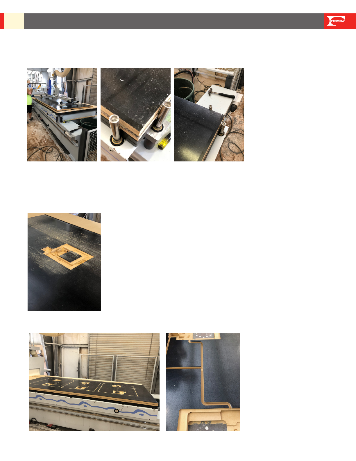
PRE-PRODUCTION – Engineering and CNC Operations
a) ENGINEERING: Load cut le for the job into the CNC for cutting. Set machine to remove entire
cavity for checking depth measurement.
b) TEST MACHINING: It is recommended that a test piece of core is run, measured and dry tted
to ensure proper machining and t before processing.
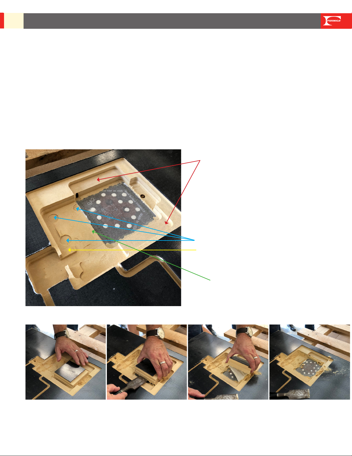
c) IMPORTANT PARTS OF CAVITY:
a. Flange for heat sink
b. Blower screws recess area
c. Power board support ange
d. Structural support of area with exception of area cut out for contact pads
d) CAVITY PERIMETER CUT:
a. Formica Group requires using a perimeter cut for the contact pad area. MDF/Particleboard/
Plywood will be removed after CNC cut is complete. For this perimeter cut, we recommend to
use 1/4” or 3/8” bit.
B. Screw Recess
A. Flange (measured from top of ange to
bottom of cavity where contract pads are,
which is 13.31mm or .524 inch)
C. Powerboard Support
D. Structural Support
INTENTEK™WIRELESS CHARGING SURFACES BY FORMICA GROUP
TECHNICAL GUIDE, USE & CARE, WARRANTY, AND INSTALLATION GUIDE
12
e) BOTTOM/UP CNC PROGRAMMING:
Formica Group understands that CNC programs dier. Formica Group will supply
CAD les that will have bottom/up measurements of the cavity. Our recommendation is to
cut cavity using a bottom/up measurement from the vacuum table. By doing this, CNC
machine will reference and cut to the deepest measurement of cavity, which is 2.3mm
(which will cut to the very back of the Intentek™ decorative face sheet). If CNC programming
requires Top/Down measurements, fabricator will need to adjust CNC Cut le.
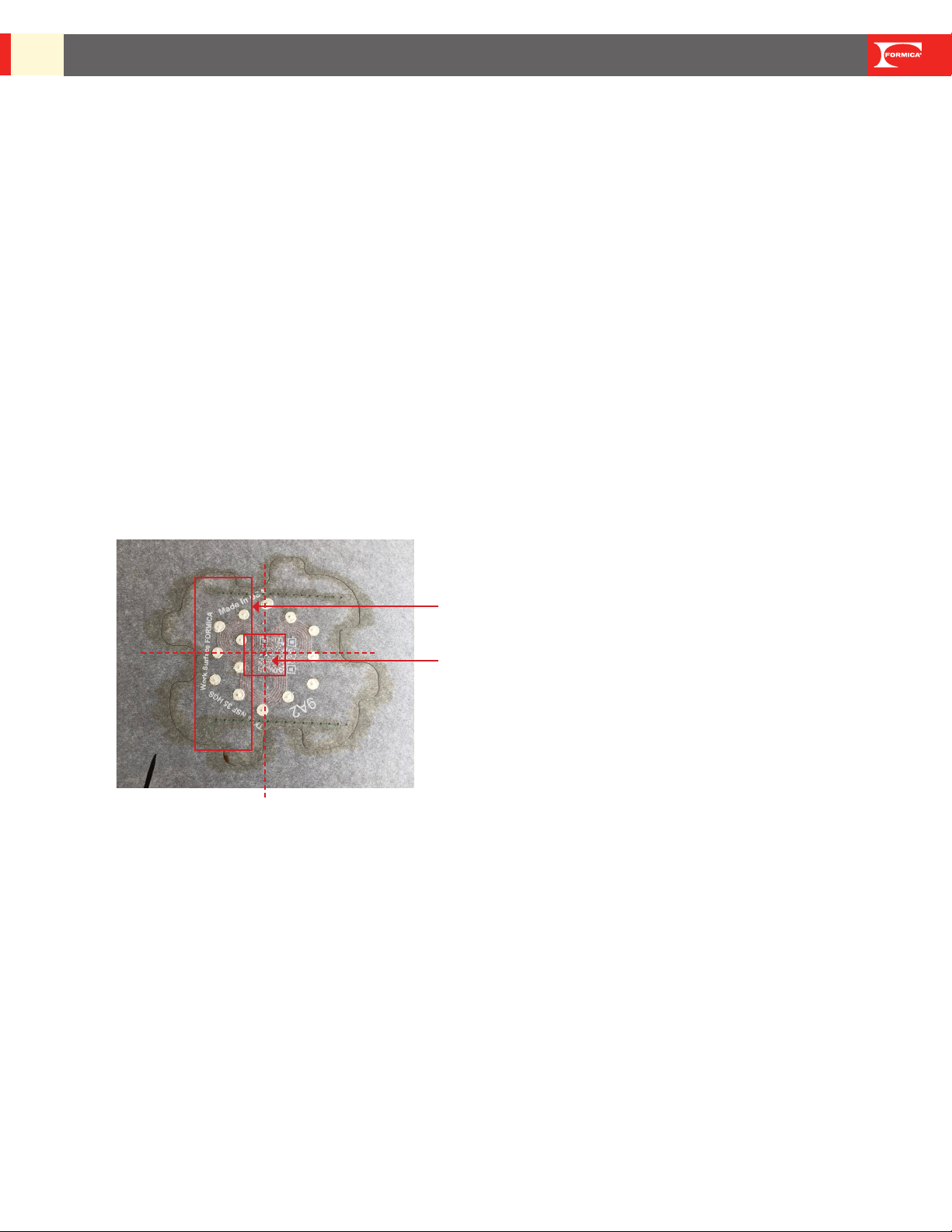
f) OPTIONAL CONFIRMATOIN OF MEASURMENTS:
Prior to fabrication, should fabricator want to conrm that laminate measurements match
the CNC Cut le, do not measure from the decorative side where the charging icon is placed.
Center point measurements can be made from backside of laminate as shown below.
CAUTION: when measuring, do not use any tools that could damage the contact pad.
Note, the end with the double layer of contact pads is where the electronics blower oulet will be.
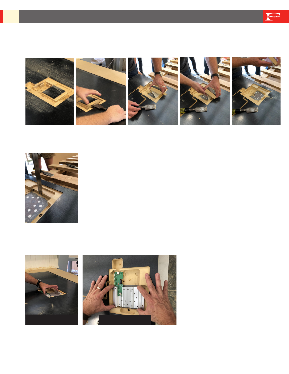
3. PRODUCTION - CNC Operations (Typical steps)
a) RESET CNC: Reset CNC program for cutting to do a perimeter cut of the deepest part of cavity
(the part where the contact pads are exposed). We do not recommend removal of material within this
area until after CNC operation is complete.
b) POSITION BOARD: Position the decorative laminate side of panel face down on the CNC table.
This end is where blower outlet will
be orientented
This is where the center point
is measured
13 INTENTEK™WIRELESS CHARGING SURFACES BY FORMICA GROUP
TECHNICAL GUIDE, USE & CARE, WARRANTY, AND INSTALLATION GUIDE
c) ALIGN BOARD: Align reference edge of panel decorative laminate sheet to the CNC alignment
pins on the vacuum table prior to initiating the cutting operation.
d) WARNING: Machining must not contact the charging zone area contact pads which will im-
pact/defeat the performance of the end product.
e) RUN CNC: Run CNC program to make all cuts into the substrate, which may include:
a. the electronics cavity or cavities into the substrate
b. wire or adapter tracks
c. attachment holes for table legs
INTENTEK™WIRELESS CHARGING SURFACES BY FORMICA GROUP
TECHNICAL GUIDE, USE & CARE, WARRANTY, AND INSTALLATION GUIDE
14
f) REMOVE CAVITY PIECE: When job is complete, remove cavity substrate piece (that was
created with the perimeter cut) from the cavity to reveal the contact pads. At this time, the 5”x5”
masking should also be removed.
g) CONFIRM CAVITY MEASUREMENT: Check to conrm the distance from the ange where
the heat sink will eventually be screwed in to the bottom of the cavity where the contact pads
are. This measurement should be 13.31 mm. (.524 inch)
h) CONFIRM FIT: Test t of heat sink to the cavity by placing into the cavity. Heat sink should not
rock side-to-side, but sit evenly in the cavity. Check to conrm the silver contact pads are visible
through the holes in the heat sink.
Heat shink should not
rock from side-to-side
Make sure all contact
pads are visbile

15 INTENTEK™WIRELESS CHARGING SURFACES BY FORMICA GROUP
TECHNICAL GUIDE, USE & CARE, WARRANTY, AND INSTALLATION GUIDE
4. PRODUCTION
a) COMPLETE EDGING AS NEEDED: Table or counter should be edged as specied.
5. ELECTRONICS INSTALLATION
a) UNSCREW MODULE: Unscrew electronic module from heat sink cover. Retain screws for nal
assembly.
b) PEEL BLUE COAT: Peel o blue peel coat from the gap pad. Take care not to pull o the gray
gap pad.
c) ALIGN HEAT SINK: Align the heat sink in the cavity by visually centering the heat sink holes on
all of the silver contact pads.

INTENTEK™WIRELESS CHARGING SURFACES BY FORMICA GROUP
TECHNICAL GUIDE, USE & CARE, WARRANTY, AND INSTALLATION GUIDE
16
d) PLACE 1ST SCREW IN HEAT SINK: Press the heat sink down and place initial screw - check
to conrm all contact pads are still visible through the holes in the heat sink.
e) SCREW IN HEAT SINK: Place the remaining three screws into heat sink and tighten.
Caution: Do not overtighten screws in the substrate.
f) CONNECT MULTIPLE CHARGING ZONES AS NEEDED: If design calls for multiple electron-
ics zones to be connected, follow instructions now that are found in the box on the next page.
If you are only installing one charge zone, skip to step g.
Wiring should be done before electronics module housing is attached in next step.
17 INTENTEK™WIRELESS CHARGING SURFACES BY FORMICA GROUP
TECHNICAL GUIDE, USE & CARE, WARRANTY, AND INSTALLATION GUIDE
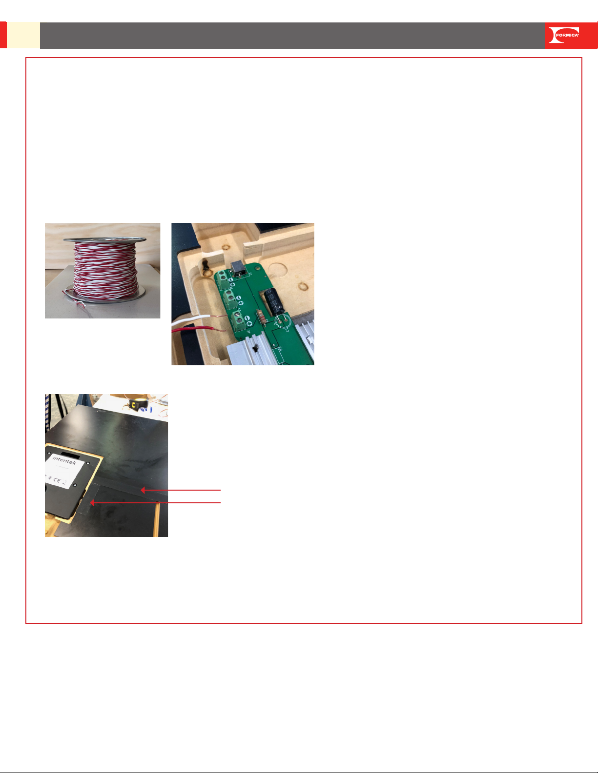
Connecting Multiple Electronics Modules to a Single AC Adapter:
REMINDERS
• Up to four electronics modules can be connected with a single power source. Use this step if the
design requires multiple electronics modules to be connected.
• 20 AWG corded wire is the minimum gauge required.
• When connecting multiple electronics units together, it is critical that instructions are followed.
The correct polarity is important, or the electronics will not operate.
• Always use two cord colors. Formica Group recommends using a red wire for positive and a
white wire for negative.
• Always cover wire when top is nished.
• Never work with electrical wiring while powered.
Sheathing coverage for
wire channels

INTENTEK™WIRELESS CHARGING SURFACES BY FORMICA GROUP
TECHNICAL GUIDE, USE & CARE, WARRANTY, AND INSTALLATION GUIDE
18
Instructions for Connecting Multiple Charging Zones Together:
a) Conrm electronics are not plugged into a power source.
b) Locate the parent electronics module (the parent is the one that will be plugged into the AC
Adapter).
c) Using a wire stripper, strip 3/16” o one end of the red and white wires to expose the wire
underneath.
d) Using a small slotted screwdriver, tighten the exposed wire of the positive (red) wire into the pos-
itive port in the parent’s power distribution board.
AC Adapter goes here.

19 INTENTEK™WIRELESS CHARGING SURFACES BY FORMICA GROUP
TECHNICAL GUIDE, USE & CARE, WARRANTY, AND INSTALLATION GUIDE
e) Using a small slotted screwdriver, tighten the exposed wire of the negative (white) wire into the
negative port in the parent’s power distribution board.
f) Measure the length of wire needed to reach the next electronics module and cut. Strip this end
to expose 3/16” of both red and white cords.
g) Using a small slotted screwdriver, tighten the exposed wire of the positive (red) wire into the pos-
itive port in the second power distribution board.
h) Using a small slotted screwdriver, tighten the exposed wire of the negative (white) wire into the
negative port in the second power distribution board.
i) Repeat until all of electronics modules have been connected.
j) Check to be certain all wires are tight in terminal strips.

INTENTEK™WIRELESS CHARGING SURFACES BY FORMICA GROUP
TECHNICAL GUIDE, USE & CARE, WARRANTY, AND INSTALLATION GUIDE
20
g) ALIGN ELECTRONICS HOUSING: Visually align the screw holes in the electronics housing
over the holes in the heat sink and use as a guide when dropping in the housing. Be careful not to
stress pogo pins
3” screws can be used to help with alignment. Thread 3” alignment screws into housing
system in opposite corners to use as guides to drop housing system in. This will help protect
pogo pins. Remove alignment screws before proceeding to next step.
h) ATTACH ELECTRONICS HOUSING: Press and attach electronics module housing to heat sink
i) SCREW IN HOUSING: Use four screws to secure housing to heat sink
Other manuals for Intentek
1
Table of contents
Other Formica Batteries Charger manuals

Popular Batteries Charger manuals by other brands


Ozito
Ozito PXBC-007U Original instructions

ULTIMATE SPEED
ULTIMATE SPEED ULG 3.8 A1 BATTERY CHARGER Operation and safety notes

VTOMAN
VTOMAN Jump 1500X user manual

Olympus
Olympus E-1 - Digital Camera SLR instructions

Samsung
Samsung EP-N5105 user manual

Adrenaline Technologies
Adrenaline Technologies iTurbo Charge IP1 user guide