Hawker PTO MOD3 User manual

PTO™MOD3
Owner’s Manual
AM-HPTOM3-OM
Rev AB February 2020
1
Battery Charger
Owner’s Manual
PTO™
MOD3
Models: PTOM1 / PTOM3 / PTOM3C (Standard
and Flex)
For parts sales, call toll-free 1-800-409-8895 and for charger technical support,
troubleshooting, and service call 1-800-251-6560.
AM-HPTOM3-OM
Rev AB February 2020
Model:
S/N:
AC Input Voltage
Installed by
Date
IMPORTANT
Read and understand your user’s manual before installing, operating, or servicing this product.
DO NOT DESTROY THIS BOOK

PTO™MOD3
Owner’s Manual
AM-HPTOM3-OM
Rev AB February 2020
2
TABLE OF CONTENTS
Important Safety Instructions .....................................3
Technical Information..................................................4
Part Number..........................................................4
Cabinet Size/Gauge Letter Codes..................4
AC Line Voltage Letter Codes........................5
Specialty Charger Options List.......................5
Serial No................................................................5
Battery Type..........................................................5
Max AH..................................................................5
No. Cells................................................................5
Max Modules .........................................................5
Config Modules......................................................5
Hertz......................................................................6
Phase....................................................................6
AC Volts.................................................................6
Config AC Amps....................................................6
Max AC Amps........................................................6
Max DC Amps........................................................6
DC Volts ................................................................6
Config DC Amps....................................................6
CEC.......................................................................6
cULus....................................................................6
Installation....................................................................7
Location.................................................................7
Wall/Floor Mount Cabinet Chargers.......................7
Electrical Connections ...........................................7
Connecting Input Power.........................................7
AC Circuit Protection..............................................7
Breaker/Fuse Chart …………………………………..7
DC Plug Polarity ....................................................8
Grounding the Charger ..........................................8
Description of Operation.............................................9
General..................................................................9
Auto Start Charge..................................................9
Charging Current ...................................................9
AC Power Fail........................................................9
Series Charging.....................................................9
Glossary.......................................................................10
Charge Blockout....................................................10
Charging Profile……………………………………….10
Cold Profile............................................................10
Thin Plate Pure Lead.............................................10
Flex Bloc Profile.....................................................10
Flex Standard Profile .............................................10
Equalization Charging............................................10
Opportunity Profile.................................................10
Standard Flooded..................................................10
Refresh Charging...................................................10
Abbreviations and Acronyms .....................................11
Operating Instructions ................................................11
Charger Control Panel.................................................12
Setting Up Charger......................................................13
Idle Screen Display................................................13
Start Menu Display.................................................13
Start Menu.............................................................13
Main Menu.............................................................13
System Setup...............................................................13
Date........................................................................13
Time .......................................................................14
DST (Daylight Savings Time)..................................14
Language................................................................14
Units.......................................................................14
Display Contrast......................................................14
Enter Password............................................................14
Change Password........................................................14
USB ..............................................................................15
Memo Data............................................................15
Save Setup Params...............................................15
Load Setup Params...............................................15
Load Control FW ...................................................15
Load Module FW...................................................15
Charger Prof. Config ...................................................15
Battery Cells..........................................................15
Battery Capacity....................................................15
Battery Temperature..............................................16
Profile....................................................................16
Charger Coefficient................................................16
Constant Current Configuration.................................16
Equalization Configuration.........................................16
Equalize Days........................................................16
Delay Time Aft Chg................................................16
Duration.................................................................17
Start Charge Configuration.........................................17
Charge Delay ........................................................17
Charge Blockout....................................................17
Cond Charge %.....................................................17
Daily Chg Countdown............................................17
Post Charge Configuration.........................................17
Cool Down.............................................................17
Refresh On/Off ......................................................17
Charger Config ............................................................18
Cabinet Bay Size...................................................18
Number of Modules ...............................................18
DC Cable Setup.....................................................18
Charger Options....................................................18
Serial Number........................................................18
Asset Number........................................................18
Reset Memos ........................................................18
Charging the Battery...................................................19
Charger Idle Display..............................................19
Starting a Charge Cycle.........................................19
Delayed Start.........................................................19
Count Down ..........................................................19
Charge Display......................................................20
End of Charge Display...........................................21
End of Charge without Equalization.......................21
End of Charge with Equalization............................21
Charger Information....................................................22
Version..................................................................22
Serial Number........................................................22
Asset Number........................................................22
Status....................................................................23
Modules.................................................................23
Modules LED Status..............................................23
Memos..........................................................................24
Memorization Access.............................................24
Memorization Display Screen ................................24
Displaying a Charge Cycle.....................................24
Fault Codes..................................................................25
Mounting Dimensions.................................................26
3 Bay Mounting Dimensions ..................................26
6 Bay Mounting Dimensions ..................................26
Maintenance and Service............................................30
Component Locations.................................................31
Technical Specifications 480V, 1ph............................33
Technical Specifications 208/220/240V, 3ph..............34
Technical Specifications 440V, 3ph............................39
Technical Specifications 480V, 3ph............................43
Technical Specifications 600V, 3ph............................47
Maintenance Log.........................................................49

PTO™MOD3
Owner’s Manual
AM-HPTOM3-OM
Rev AB February 2020
3
IMPORTANT SAFETY INSTRUCTIONS
WARNING: THE SHIPPING PALLET MUST BE REMOVED FOR PROPER AND SAFE
OPERATION.
1. This manual contains important safety and operating instructions. Before using the battery charger, read all
instructions, CAUTIONs and WARNINGs on the battery charger, the battery and the product using the battery.
2. This battery charger is designed to charge flooded and sealed lead-acid batteries. Read and understand all setup
and operating instructions before using the battery charger to prevent damage to the battery and to the charger.
3. Do not touch non-insulated parts of the output connector or the battery terminals to prevent electrical shock.
4. During charge, batteries produce hydrogen gas which can explode if ignited. Never smoke, use an open flame, or
create sparks in the vicinity of the battery. Ventilate well when the battery is in an enclosed space.
5. Do not connect or disconnect the battery plug while the battery is charging. Doing so will cause arcing and burning
of the connector resulting in charger damage or battery explosion.
6. Lead-acid batteries contain sulfuric acid which causes burns. Do not get in eyes, on skin, or on clothing. In cases
of contact with eyes, flush immediately with clean water for 15 minutes. Seek medical attention immediately.
7. Only factory qualified personnel can service this equipment. De-energize all AC and DC power connections before
servicing the charger.
8. The charger is not for outdoor use.
9. Do not expose the charger to moisture. Operating conditions should be 32º to 113º F (0º to 45º C); 0 to 70% relative
humidity.
10. Do not operate the charger if it has been dropped, received a sharp hit, or otherwise damaged in any way.
11. For continued protection and to reduce the risk of fire, install chargers on a floor of non-combustible material such
as stone, brick, or grounded metal.

PTO™MOD3
Owner’s Manual
AM-HPTOM3-OM
Rev AB February 2020
4
TECHNICAL INFORMATION
There are two nameplates located on the outside of the charger and should be used to check the
application before installation. The “Main” nameplate includes the UL Model number and the
ratings of the cabinet at its full capacity, while the “Configured Ratings” nameplate includes the
Part number and the ratings of the cabinet as configured. The Configured Ratings nameplate label
must be replaced when adding or removing modules permanently in the field.
Part Number and UL Model Number
The UL Model Number specifies the characteristics of a full cabinet charger, while the Part Number
specifies the characteristics of the cabinet as configured, plus all options. The Part Number is
required in any discussion or correspondence regarding this unit.
PTOM3-48F-240YR
Model type
Phase
(-) for Standard or (C) for CEC
Max DC Volts
Cabinet Size
Max DC Current @ Max DC Volts
Input Voltage Code
Options
Cabinet Size/Gauge Letter Codes
The following table describes the letter codes to be used in charger part numbers to indicate the
DC output voltage(s) of the charger.
Letter
Code
Module
Positions
Standard Cable
Gauge
Comments
C
3
2/0
Three slot, 3.5kW cabinet
F
6
3/0
Six slot, 3.5kW cabinet

PTO™MOD3
Owner’s Manual
AM-HPTOM3-OM
Rev AB February 2020
5
AC Line Voltage Letter Codes
The following table describes the letter codes used in the charger part number to indicate the
nominal AC line voltage(s) and frequency at which the charger is designed to operate.
Letter
Code
Voltage(s)
(volts rms)
Line
Frequency
(Hertz)
Comments
C
600
50/60
600 VAC only
G
208/220/240
50/60
208/220/240 VAC
H
440
50/60
440 VAC only
Y
480
50/60
480 VAC only
Specialty Charger Options List
Suffix
Description
1
15 Ft of DC cable.
2
20 Ft of DC cable.
3
25 Ft of DC cable.
4
30 Ft of DC cable.
E
LAN (Ethernet Compatible)
F
Red/Green Next Battery Capable –used in conjunction with BSI and BSS
R
Remote control capable ( order remote control separately)
V
PLC capable
Serial No.
This is the serial number that indicates complete information about the charger. It must be supplied
with the part number on any correspondence or discussion regarding this charger.
Battery Type
The chemical content of the battery this charger is designed to charge:
L-A = Lead Acid.
Max AH
This number indicates the maximum Amperes-Hours (AH) capacity of this charger. Charging
batteries of AH capacities not specified here will cause the charger to deviate from the specifications.
No. Cells
This is the number of cells this charger is designed to charge.
Max Modules
This is the maximum number of power modules that can be installed into the charger cabinet.
Config Modules
This is the actual number of power modules installed in the charger cabinet.

PTO™MOD3
Owner’s Manual
AM-HPTOM3-OM
Rev AB February 2020
6
Hertz
This is the frequency in cycles per second of the AC input voltage this charger is designed to operate
on. Do not operate charger at a different frequency or from a generator with unstable frequency.
Phase
Number "1" indicates a Single Phase Charger and number “3” indicates a Three Phase Charger.
AC Volts
This is the input voltage accommodated by this charger.
Failure to use the correct voltage will result in damage to the charger and/or the battery.
IMPORTANT: THE CHARGER WILL OPERATE ONLY ON NOMINAL AC LINE VOLTAGES
INDICATED ON THE NAMEPLATE.
Config AC Amps
This is the AC current that this charger will draw with the number of power modules shown in
Config Modules on the nameplate.
Max AC Amps
This is the Maximum AC current this charger will draw from AC power. This charger must be
connected to a branch circuit protection in accordance with the National Electrical Code NFPA70
and local codes. (AC breaker/fuse values can be found on a decal outside the charger.)
Max DC Amps
This is the maximum DC current that this charger cabinet will deliver to a discharged battery when
fully populated with power modules.
DC Volts
This is the rated DC output voltage of the charger.
Config DC Amps
This is the DC current that this charger will deliver to a discharged battery with the originally-furnished
(Config Modules) number of power modules.
CEC
This logo is applied to chargers that are certified with the California Energy Commission in
compliance with Appliance Efficiency Regulations:
cULus
This logo is applied to chargers that have been tested to applicable standards and requirements by
Underwriters Laboratories (UL) and the Canadian Standards Association (CSA):

PTO™MOD3
Owner’s Manual
AM-HPTOM3-OM
Rev AB February 2020
7
INSTALLATION
WARNING: THE SHIPPING PALLET MUST BE REMOVED FOR PROPER AND SAFE
OPERATION
Location
For maximum trouble-free service, choose a location which is free of excess moisture, dust and
corrosive fumes. Also, avoid locations where temperatures are high or where liquids will drip on the
charger. Follow charger warning label when mounting on or over a combustible surface. Do not
obstruct the ventilating openings.
Wall/Floor Mount Cabinet Chargers
The charger must be permanently mounted in a vertical position. The lower part of the charger must
be at least 12 inches from the charger below if installed above another charger, and the upper part
12 inches from the ceiling. The distance between two chargers must be no less than 12 inches. Use
the mounting kit supplied with the charger. See the Mounting Dimensions section at the end of this
manual for proper Wall and Floor mounting.
NOTE: Ambient temperature cannot exceed 113° F (45° C).
Electrical Connections
To prevent failure of the charger, be sure it is connected to the correct line voltage.
WARNING: MAKE SURE THE POWER TO THE CHARGER IS OFF AND THE BATTERY IS
DISCONNECTED BEFORE CONNECTING THE INPUT POWER TO THE TERMINALS OF
THE CHARGER.
Connecting Input Power
Connect the input power to the appropriate terminals, including ground. For screw type terminals,
torque to 15 in-lb. Follow your local and National Electric Code in making these connections.
AC Circuit Protection
The user must provide suitable branch circuit protection and a disconnect method from the AC power
supply to the charger to allow for safe servicing.
Breaker/Fuse Chart
AC Amps
(A)
Breaker/Fuse size
(A)
1 –12
15
12.1 –16
20
16.1 –20
25
20.1 –24
30
PTO™MOD3
Owner’s Manual
AM-HPTOM3-OM
Rev AB February 2020
8
24.1 -28
35
28.1 - 32
40
32.1 - 36
45
36.1 - 40
50
40.1 - 48
60
48.1 - 56
70
56.1 - 64
80
64.1 - 72
90
72.1 - 80
100
80.1 - 88
110
88.1 - 100
125
DC Plug Polarity
The charging cables are connected to the DC output of the charger with the red cable to the positive
bus bar, and the black cable to the negative bus bar. The red cable is terminated into the “+” side of
the battery connector, and the black cable is terminated into the “-“side of the connector. The output
polarity of the charger must be observed when connecting to the battery (read warning above).
Improper connection will open the DC fuses in the power modules.
DANGER: FAILURE TO GROUND THE CHARGER COULD LEAD TO FATAL ELECTRIC
SHOCK. Follow local and National Electric Code for ground wire sizing.
Grounding the Charger
Connect incoming grounding conductor to the ground lug provided on the charger support panel.
Torque the Ground wire to 15 in-lb. This lug is marked as shown:

PTO™MOD3
Owner’s Manual
AM-HPTOM3-OM
Rev AB February 2020
9
DESCRIPTION OF OPERATION
General
The PTO™MOD3 series of chargers are compatible with batteries at 24, 36, 48 volts or 72, 80 volts,
depending on model.
PTO™MOD3 chargers are microprocessor-controlled. The processor calculates the battery’s
capacity so that the charging profile can be automatically adapted to the battery’s actual state over
a wide range of capacities. The charging coefficient is maintained absolutely on all types of batteries.
PTO™MOD3 chargers adapt to the battery’s capacity and its discharge level.
PTO™MOD3 chargers can easily be set to charge flooded batteries used in cold or freezer storage
applications, standard flooded or opportunity profiles. This battery charger is also designed to charge
flooded and sealed lead-acid storage batteries within the range of the cell and amp-hour rating as
marked on the nameplate.
Auto Start Charge
When a battery is connected to the charger, the control board senses the voltage and after a 20
second delay, the charger starts charging the battery automatically.
Charging Current
Charging current is determined by the charger based on battery voltage and its state of charge.
Charging current declines automatically as battery voltage rises during the charge. As the battery
charges, the graphical LCD display will output various charge parameters including the charging
current.
AC Power Fail
If the AC power fails while the battery is connected to the charger during a charge cycle, the charger
will reset and start a new charge cycle when power is restored. All charger settings as well as the
time and date are preserved.
Series Charging
In series charging, the voltages of both batteries add up and must match charger’s nameplate DC
Volts rating. The charger’s amp-hour rating must be equal to each of the batteries’ AH rating. Charge
cycle will not start unless both batteries are connected.

PTO™MOD3
Owner’s Manual
AM-HPTOM3-OM
Rev AB February 2020
10
GLOSSARY
Charge Blockout
This function prevents the charger from charging the battery during the block out time window. If a charge
cycle has started before the block out window it is inhibited during the block out window and will automatically
restart the charge cycle at the end of the block out window.
Charging Profile
The charging profile defines the rate of current charge over time. The charger adapts to the battery’s condition
and level of discharge.
Cold Profile
This is a charging profile that allows the configuration of the charger for use with batteries in cold storage
application. The profile is an IEI (constant current, constant voltage, constant current) type with a number of
user configurable parameters.
Thin Plate Pure Lead (TPPL)
This is an advanced lead acid battery design used in FLEX batteries. TPPL technology provides longer
service life, higher power density, longer shelf life and fast recharge capabilities.
Flex Bloc Profile
This charging profile allows charging of Flex bloc batteries at rates up to 0.7C.
Flex Standard Profile
This charging profile allows charging of FLEX 2v cell batteries at rates up to 0.25C.
Equalization Charging
Equalization charging, performed after normal charging, balances the electrolyte densities in the battery’s
cells.
Opportunity Profile
The OPPOR charge profile is used when opportunity charging is desired. It has a start rate of 25% of the
batteries rated amp hour capacity, requires one complete recharge in every 24 hours of service and must
have an equalize charge done once a week which is programmed to run automatically.
Operation:
During opportunity charging the user can plug the battery in and charge it during breaks, lunch or any
work stoppage time. One time per day the battery must receive a full standard recharge. The complete
charge must be programmed for a delay that’s long enough so that the complete charge will not occur
during normal operation. Sufficient time should be scheduled after the full charge to allow the battery
to completely cool to ambient temperatures before use.
Note: The user must configure the charger for the day of the week that the equalize charge will take
place.
Standard Flooded
The profile is an IEI (constant current, constant voltage, constant current) type with a number of user
configurable parameters.
Refresh Charging
Refresh or maintenance charging enables the battery to be maintained at maximum charge all the time that
it is connected to the charger. Refresh charge is applied at a predetermined intervals after charge is complete
and battery remains connected to charger.

PTO™MOD3
Owner’s Manual
AM-HPTOM3-OM
Rev AB February 2020
11
ABBREVIATIONS AND ACRONYMS
AH Amperes-Hours
AWG American Wire Gauge
AVAIL Available
BBWC™ Battery Boss Wireless Communication
CEC California Energy Commission
DoD Depth of Discharge
GND Ground
kW Kilowatt
L-A Lead Acid
LCD Liquid Crystal Display
LED Light Emitting Diode
TFT Thin Film Transistor
USB Universal Serial Bus
OPERATING INSTRUCTIONS
The PTO™MOD3 series of chargers are compatible with batteries at 24, 36, 48 volts or 72, 80 volts
(depending on the version supplied).
Battery voltage and Amp-hour size must be programmed into the charger for it to charge properly.
Several charging profiles are available (Standard Flooded, Opportunity, Cold) based on the
configuration chosen by the operator. If the charger is loaded with the Flex firmware then the
selectable profiles (Flex Standard and Flex Bloc) are available. Furthermore, Equalization and
Refresh charges are integrated.

PTO™MOD3
Owner’s Manual
AM-HPTOM3-OM
Rev AB February 2020
12
Charger Control Panel
Ref
Function
Description
1.
Graphical LCD Display
Display charger operation info/Menus
2.
USB Port
Log charge data, and update firmware
3.
Navigate UP button
Navigate menus/Change values
4.
ENTER/STOP and START button
Select menu items/Enter values/Stop and
restart battery charge
5.
Navigate RIGHT/EQUALIZE button
Scroll right/Start equalize or desulfation
6.
Navigation DOWN button
Navigate menus/Change values
7.
Navigation LEFT/ESC button
Enter Main Menu/Scroll left/Exit menus
8.
RED fault indicator
OFF = no fault
FLASHING = fault detected
9.
YELLOW charging indicator
OFF = charge paused
FLASHING = countdown
ON = charging in progress
10.
GREEN charge complete indicator
OFF = charger OFF or battery not available
FLASHING = charge complete
ON = charger in idle mode
1
2
10
9
8
7
6
5
4
3

PTO™MOD3
Owner’s Manual
AM-HPTOM3-OM
Rev AB February 2020
13
SETTING UP CHARGER
Idle Screen Display
Start Menu Display
Start Menu
When the charger is idle, the display shows “CONNECT BATTERY”. To enter the Start Menu, press
and hold <ESC>, the Start Menu is then displayed. The current menu is automatically exited after
two minutes of inactivity or can be exited voluntarily by pressing the <ESC> button.
1. Select a menu option using the Up/Down buttons. The selected menu will be highlighted.
2. Display the highlighted menu screen by pressing the Enter button.
3. Return to the main menu by pressing the Esc button.
Main Menu
Navigate to the main menu by selecting Setup under the Start Menu.
SYSTEM SETUP
Date
Sets the date of the charger (MM/DD/YY).

PTO™MOD3
Owner’s Manual
AM-HPTOM3-OM
Rev AB February 2020
14
Time
Sets the time of the charger (24 Hr Clock).
DST (Daylight Saving Time)
Enable or disable automatic clock adjustment for daylight saving time. When enabled, time will
move ahead one hour at 02:00 on the second Sunday in March and will move back one hour at
02:00 on the first Sunday of November. The charger must be powered up at the time of the change
for it to take effect.
Language
Selects the language displayed in the menus.
Units
Selects Metric or English units for temperature, length and cable gauge.
Display Contrast
Adjusts the brightness of the LCD display.
ENTER PASSWORD
This is where the password is entered to gain access to service level menus by authorized Hawker
service personnel.
1. Use the Up/Down buttons to select the correct alphanumeric character.
2. Use the Left/Right buttons to move the cursor either left or right.
3. Once the correct password is entered press the Select.
If the correct password is entered the display will automatically jump to the main menu with the
service level menu displayed.
MAIN MENU
System Setup
•Enter Password
•Change Password
•USB
•Charge Prof. Config
•Constant Current
•Equalize
•Start Charge
•Post Charge
•Charger Config
CHANGE PASSWORD
Enter the current password used to get the above menu. If the password is entered correctly the
display will ask to enter a new password. After a new password is entered press the Enter
button. Don’t forget the new password or you will not be able to get into the charger settings
anymore.

PTO™MOD3
Owner’s Manual
AM-HPTOM3-OM
Rev AB February 2020
15
USB
Memo Data
Enables the storage of charge Memorizations to a USB data storage device (aka memory
stick, thumb drive). To record memos:
1. Insert the data storage device in the USB port on the front of the charger.
2. Go to Start Menu->Enter Password->USB->Record Memo. Select “ON”.
3. Display will show “Memo File: .csv
4. The default file name is the charger serial number. Name the file and press the Enter
button to save.
5. Remove data storage device from USB port. The file, in CSV format (useable with
Memo Report or Excel), will be stored in the data storage device under the name
“MDDDHHMM.CSV” where:
M: is for Memorization data file
DDD: Day of the year
HH: Hour of file creation
MM: Minute of file creation
Save Setup Params
Enables the storage of the charger Setup Parameters to a USB data storage device (aka
memory stick, thumb drive).
Load Setup Paramrs
Enables the uploading of the charger Setup Parameters from a USB data storage device (aka
memory stick, thumb drive).
Load Control FW
Enables the updating of the chargers internal firmware. Firmware updates will be provided by
Hawker.
Load Module FW
Enables the updating of the power modules internal firmware. Firmware updates will be provided
by Hawker.
CHARGE PROF. CONFIG
Battery Cells
This allows the charger to be adjusted for the number of cells in the battery being charged.
Allowable cell settings: 12, 18, 24, 36, 40. Scroll to find correct battery and hit Enter to select.
This is critical it be set to match the battery and match the module types in the charger.
Battery Capacity
This adjusts the battery Ah capacity used by the charger to determine start and finish rates, and
must match the Ah capacity of the battery being charged. Allowable Ah sizes: 100Ah to 2500Ah.
This must match the battery Ah size because this charger does not read a BBWC nor is it
automatic like the LifePlus series chargers.

PTO™MOD3
Owner’s Manual
AM-HPTOM3-OM
Rev AB February 2020
16
Battery Temperature
Defines the average operating battery temperature before the charge. It is recommended the
average electrolyte temperature be entered, especially in cold areas and when Opportunity
charging. If not in Cold profile ranges allowed from 60°F to 149°F. If in Cold range is 5°F to 50°F.
Profile
For selecting the right charging profile for the application. To set the correct profile the charger
will need to have the appropriate firmware loaded. If a Flex battery you will need to have
firmware FLEX-VX.XX or if it’s a flooded battery you need to have PTOM3-VX.XX in the charger.
(verify X.XX is the latest available version if you are updating the charger)
To install firmware follow all steps below. If you have the
appropriate firmware installed already skip to step 8.
1. Insert flash drive in USB port with appropriate firmware
installed.
2. Enter password and go to USB menu.
3. Select Load Control FW.
4. Using the down arrow button, select firmware file from
the list on screen and hit Select button.
5. Firmware will automatically load at this point. Wait until
it finishes and splashes the Hawker startup screen
before removing the flash drive.
6. Reenter password.
7. Scroll down to Charger Prof. Config and select Profile.
8. Select Standard, Opportunity, or Cold. Or if the charger
is loaded with the Flex firmware the selectable profiles
are Flex Bloc and Flex Standard.
Charge Coefficient
Change setting for California Energy Commission compliant
chargers. Allowable range 1% to 9%. Should normally be at
9%.
CONSTANT CURRENT CONFIGURATION
Caution: This mode is for use by trained service technicians only. For instructions on
use see charger service manual.
EQUALIZE CONFIGURATION
Equalize Days
Select day or days of the week to equalize the battery. Any combination of one or more days
may be selected or none may be selected. Hit Enter next to day to be selected.
Delay Time Aft Chg
Sets the delay between the normal charge and the equalization charge from 0 to 24 Hrs.

PTO™MOD3
Owner’s Manual
AM-HPTOM3-OM
Rev AB February 2020
17
Duration
Sets the equalization time from 00:05 to 23:59 (hh:mm).
NOTE:
If duration is set below 5 minutes the charge will default back to the factory setting for that profile. If
not using this charger to equalize the battery, select no days of the week for equalize.
START CHARGE CONFIGURATION
Charge Delay
•Charge Delay Type: OFF or Time After Connect
•Time After Connect: Charge is delayed for the amount of time entered
Charge Blockout
ON/OFF: sets charge block out ON or OFF.
Block out Days: Select day or days of the week to block out charge. Any combination of one or
more days may be selected or none may be selected.
Block out Start –Sets block out start time. Block
out End –Sets block out end time.
Cond Charge %
Sets conditional charge %.
The charger will only commence the charge if the battery has reached the limit of depth of
discharge (DoD) of more than x%. For example if the user wants to charge the battery only if it
is discharged more than 30%, the parameter 30 has to be entered in the conditional charge. The
0 value disables the function. Allowed range 0 to 70%.
Daily Chg Countdown
Set time delay in minutes for charger to perform complete charge when running Opportunityprofile.
This setting is not used with other profiles. Allowed range 0 to 480 minutes.
POST CHARGE CONFIGURATION
Cool Down
•Cool Down On/Off: Sets this function On or Off. If enabled the charger will not show
available after a charge until the time set has expired allowing batteries to cool.
•Cool Down Time: Sets time for Cool Down.
Refresh ON/OFF
Sets refresh mode ON or OFF.
Once charging is complete, as long as the battery remains connected, refresh charging is
automatically initiated to retain the battery’s charge.

PTO™MOD3
Owner’s Manual
AM-HPTOM3-OM
Rev AB February 2020
18
CHARGER CONFIG
Cabinet Bay Size
This can only be accessed by entering the higher level password. Select cabinet size to match the
actual cabinet size.
Number of Modules
This can only be accessed by entering the higher level password. Enter number of modules
installed in charger. Limited by the cabinet selected in Cabinet Bay Size.
DC Cable Setup
•Cable Length: Select the length of DC cables from the charger to the battery terminals.
One foot increments from 2 to 200 Ft (0.6 to 60.9 m).
•Cable Size: Sets the DC cable gauge. Selections #2, #1, 1/0, 2/0, 3/0, 4/0 AWG.
Charger Options
•Select Options: choices are Remote, BSI or Electrovalve. If
using one of these charger options, that option must be
enabled.
•I/O Test is used to test the functionality of each option. Use the up and down
buttons to highlight the correct I/O test. Particular Option Must be enabled first.
oTest Inputs: Push the appropriate button on the external device and observe state
of the test box in the menu.
oTest Outputs: Push the Up button to start the test and the Down button to stop the
test.
Serial Number
The charger Serial Number can be changed. This number must match the number on the
charger nameplate attached to the side of the cabinet.
Asset Number
Each charger may be assigned a unique asset number using any combination of
Alpha/Numeric Characters.
Reset Memos
Resets and clears all memorizations and status history.
WARNING: ONCE THE MEMORIZATIONS AND STATUS HAVE BEEN CLEARED
THEY CANNOT BE RECOVERED.
PTO™MOD3
Owner’s Manual
AM-HPTOM3-OM
Rev AB February 2020
19
CHARGING THE BATTERY
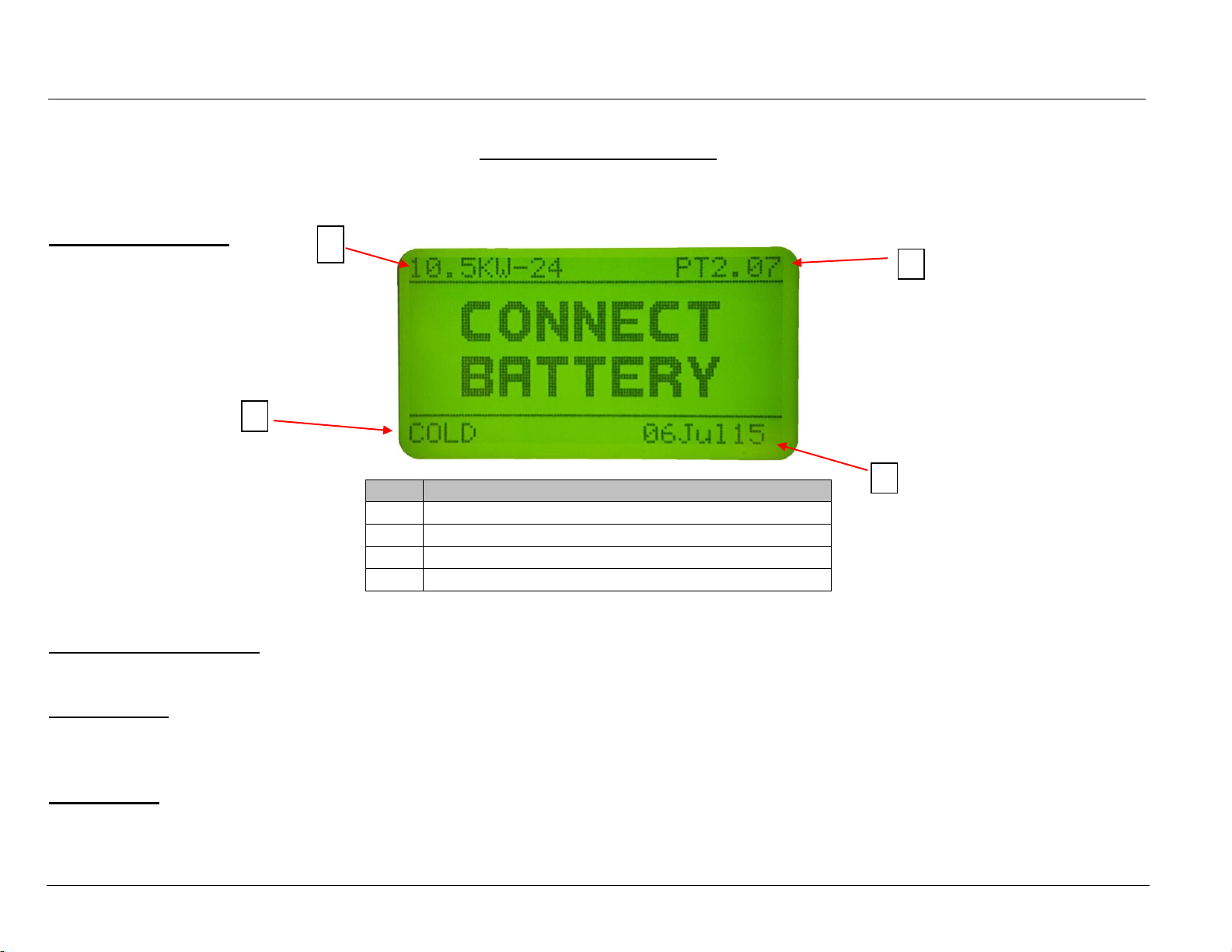
Once the charger is setup by a qualified service person, charging begins when a battery of the proper type, capacity and voltage is
connected to the charger. With the charger in idle mode (No battery connected), the display will show the following information:
Charger Idle Display
S11
-36-48V U
Starting a Charge Cycle
The charger will start automatically when a battery is connected, or by pushing the Stop/Start button if the battery is already connected.
Delayed Start
If the charger is programmed for delayed start, charging will begin following that delay. When the battery is plugged into the charger,
the display shows the time remaining before the programmed charging starts.
Count Down
Effective charging starts after a 20 second countdown. The charger uses Profile, Capacity and Temperature settings programmed in
the Configuration menu.
Ref
Description
1
Charger Type
2
Firmware Version
3
System Time and Date
4
Charge Profile
1
2
4
3
PTO™MOD3
Owner’s Manual
AM-HPTOM3-OM
Rev AB February 2020
20
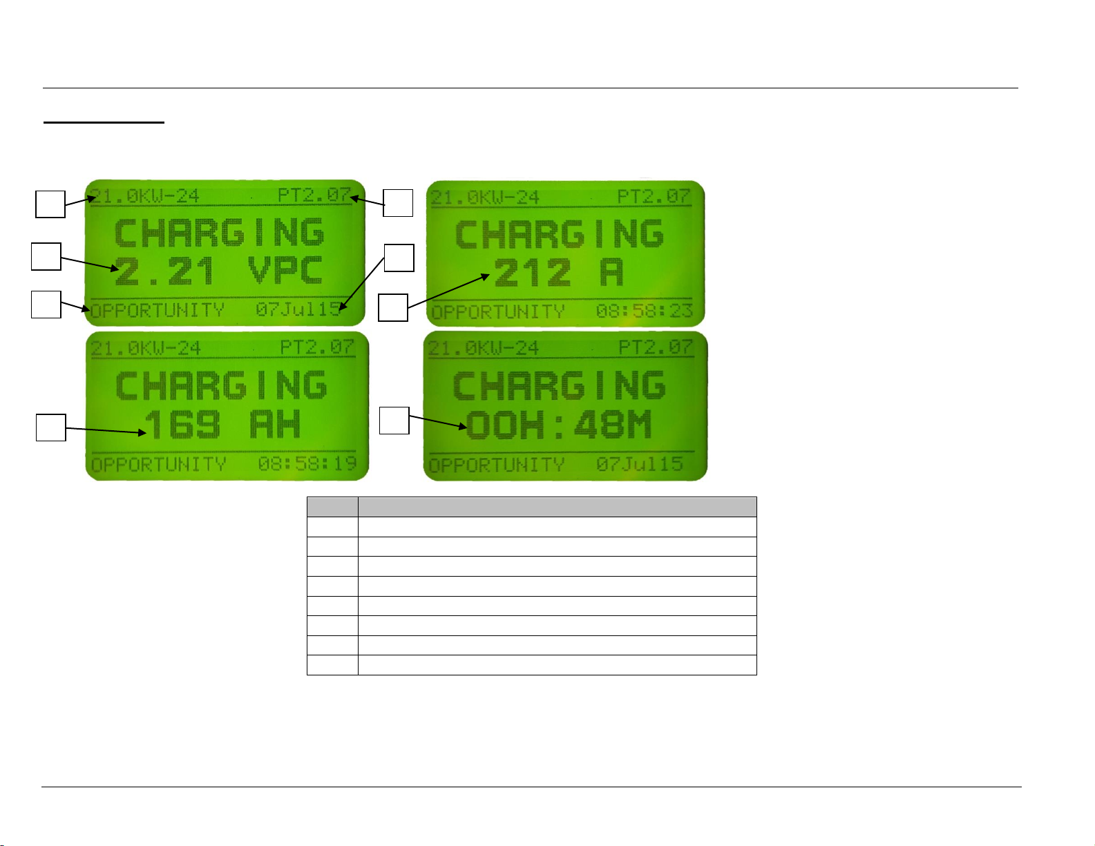
Charge Display
A few moments into the effective charge, the display will begin alternating between the following charging information:
Ref
Description
1
Charger Type
2
Firmware Version
3
Charge Profile
4
System Time and Date
5
Volts Per Cell
6
DC Amps
7
AH Returned to Battery
8
Charge Time
1
4
3
5
2
8
7
6
This manual suits for next models
3
Table of contents
Other Hawker Batteries Charger manuals

Hawker
Hawker MotionLine User manual

Hawker
Hawker MasterLine puls/EU User manual

Hawker
Hawker Life IQ User manual

Hawker
Hawker LIFEPLUS MOD3 Series User manual

Hawker
Hawker MultiLine W0Wa User manual

Hawker
Hawker EnerSys LifeSpeed IQ User manual

Hawker
Hawker Lifetech User manual

Hawker
Hawker LIFESPEED MOD3 User manual


