Formulatrix MANTIS User manual

Original Instructions
Applies to Continuous Flow, LAM, ACC, LC3, RFID models
January 2018
MAG-V40R018
© 2018 FORMULATRIX. All Rights Reserved.
User’s Guide
MANTIS®Liquid Handler

FORMULATRIX Product Information
Formulatrix.com
FORMULATRIX Corporate Headquarters
10 DeAngelo Drive, Bedford, MA 01730 USA Phone: +1 781 788 0228
For information requests, email [email protected]. For sales inquiries, email [email protected]. For support,
email [email protected]. To comment on FORMULATRIX documentation, email publications@formulatrix.com.
FORMULATRIX European Representative
Carl Pedersen
Support, Europe
Phone: +44 7805512001

Table of Contents
Chapter 1: Introduction.....................................................................................................................................................................................................................................1
Symbols and Conventions.................................................................................................................................................................................................................................................2
Chapter 2: Safety Information.......................................................................................................................................................................................................................3
Introduction...................................................................................................................................................................................................................................................................................3
Regulatory Compliance.......................................................................................................................................................................................................................................................3
Equipment Safety Guidelines..........................................................................................................................................................................................................................................4
Mechanical Hazards................................................................................................................................................................................................................................................................4
Electrical Hazards.....................................................................................................................................................................................................................................................................4
Chapter 3: Specifications................................................................................................................................................................................................................................5
Physical Dimensions...............................................................................................................................................................................................................................................................5
Computer Requirements....................................................................................................................................................................................................................................................7
Electrical Requirements.......................................................................................................................................................................................................................................................7
Chapter 4: Overview..........................................................................................................................................................................................................................................8
Key Features................................................................................................................................................................................................................................................................................8
Chapter 5: Hardware Overview..................................................................................................................................................................................................................10
MANTIS Components.........................................................................................................................................................................................................................................................10
Chapter 6: Initial Setup...................................................................................................................................................................................................................................13
Setting Up the MANTIS......................................................................................................................................................................................................................................................13
Adding Plate Types to the Plate Type Library.................................................................................................................................................................................................14
Adding Circular Plates to the Plate Type Library...........................................................................................................................................................................................23
Adding Stock Reagents to the Reagent List.....................................................................................................................................................................................................26
Calibrating the Chip Port Positions...........................................................................................................................................................................................................................27
Calibrating Continuous Flow Chips..........................................................................................................................................................................................................................27
Default Volume and Tubing Length Recommendation...........................................................................................................................................................................28
Chapter 7: Software Overview...................................................................................................................................................................................................................30
Main Software Overview..................................................................................................................................................................................................................................................30
Device Control Panel...........................................................................................................................................................................................................................................................32
Input Control Panel...............................................................................................................................................................................................................................................................35
Dispense List Designer.......................................................................................................................................................................................................................................................41
Well Selection Patterns.....................................................................................................................................................................................................................................................43
Status Bar.....................................................................................................................................................................................................................................................................................43
Chapter 8: Setting Up the Hardware.......................................................................................................................................................................................................44
Chapter 9: Dispensing With the MANTIS...............................................................................................................................................................................................47
Designing a Dispense.........................................................................................................................................................................................................................................................47
Designing a Multi-Plate Dispense.............................................................................................................................................................................................................................49
iii

iv
Viscous Dispensing Tips and Tricks.........................................................................................................................................................................................................................51
Adding a Dispense Delay.................................................................................................................................................................................................................................................53
Using Excel to Edit a Dispense Design..................................................................................................................................................................................................................53
Creating and Using Protocols.......................................................................................................................................................................................................................................54
Creating and Using Reagent Configurations....................................................................................................................................................................................................55
Priming the Chips...................................................................................................................................................................................................................................................................56
Executing a Plate Dispense............................................................................................................................................................................................................................................57
Recovering Excess Reagent Volume.....................................................................................................................................................................................................................58
Importing Dispense Data..................................................................................................................................................................................................................................................59
Reloading Dispense Data................................................................................................................................................................................................................................................68
Normalizing Concentration............................................................................................................................................................................................................................................69
Cleaning the Chips................................................................................................................................................................................................................................................................73
Dispensing ROCK MAKER®Crystallization Software Plate Designs...............................................................................................................................................74
Dispensing FORMULATOR®Screen Builder Plate Designs..................................................................................................................................................................75
Performing a MANTIS Factory Reset......................................................................................................................................................................................................................76
Resolving Dispense List Errors....................................................................................................................................................................................................................................77
Using the Options Menu...................................................................................................................................................................................................................................................78
Using the Security Settings............................................................................................................................................................................................................................................83
Chapter 10: Large Capacity Chip Changer (LC3)...............................................................................................................................................................................88
LC3 Components...................................................................................................................................................................................................................................................................88
Setting Up the LC3 for a Dispense............................................................................................................................................................................................................................91
Tuning the LC3 Carousel..................................................................................................................................................................................................................................................92
Chapter 11: MANTIS Radio-Frequency Identification (RFID)........................................................................................................................................................95
Using the RFID Functionality in MANTIS..............................................................................................................................................................................................................97
Chapter 12: MANTIS Configuration........................................................................................................................................................................................................101
Configuring MANTIS-ROCK MAKER Integration..........................................................................................................................................................................................101
Configuring MANTIS-FORMULATOR Integration.......................................................................................................................................................................................104
Chapter 13: Deck Geometry Correction..............................................................................................................................................................................................106
Chapter 14: System Maintenance...........................................................................................................................................................................................................108
Sterilizing MANTIS Chips ..............................................................................................................................................................................................................................................108
Chapter 15: Troubleshooting and FAQs...............................................................................................................................................................................................110
Troubleshooting....................................................................................................................................................................................................................................................................110
FAQs...............................................................................................................................................................................................................................................................................................114
Accessories........................................................................................................................................................................................................................................................115
Index......................................................................................................................................................................................................................................................................117

1
Introduction
Chapter 1
Thank you for purchasing the MANTIS, a low dead-volume, non-contact liquid dispenser.
The unique design of this small machine minimizes dead volume and accepts pipette tip or
tube inputs.
Your MANTIS must be used in the manner described in this user’s guide. Any other use may
result in damage to your MANTIS or personal injury. FORMULATRIX, Inc. is not responsible
in whole or in part for any damages caused by: improper use, unauthorized alterations,
adjustments or modifications, failure to comply with the procedures outlined in the MANTIS
User’s Guide, or use of the products in violation of applicable laws, rules, or regulations.
Except as otherwise expressly provided in this user guide, any alteration, adjustment, or
modification to the products will void the product warranty.
Read, understand, and observe all safety information and instructions in this manual before
using your MANTIS. Please note specific safety requirements as explained in this user’s guide.
Failure to follow these instructions could result in serious personal injury.
Please save this guide for future reference and have it available to all operating personnel.
The MANTIS is manufactured to the current technical safety-relevant regulations.

2
This icon denotes a caution and advises you of precautions to take.
This icon denotes a prohibited action.
This icon denotes a compulsory action and advises you of actions
you must take.
This icon denotes a caution relating to electric shock and advises you
of precautions to take.
This icon denotes a fire hazard and advises you of precautions to
take.
This icon denotes a warning.
Bold text denotes items you must select or click in the software, such
as menu items and dialog box options. Bold text also denotes
parameter names.
bold
Text in this font denotes text or characters you should type from the
keyboard.
monospace
Symbols and Conventions
MANTIS User's Guide | Chapter 1: Introduction

3
The safety recommendations in this guide are basic guidelines. If the lab where the
MANTIS is to be kept has additional safety guidelines they should be followed as well,
along with all applicable national and international safety codes.
FORMULATRIX products are CE (Conformité Européenne) Machinery, Low Voltage, and
EMC directive compliant. If necessary, request the official Declaration of Conformity
(DOC) from FORMULATRIX.
Safety Information
Chapter 2
Introduction
Only FORMULATRIX personnel are permitted to transport, assemble, or service the
Use only parts supplied or recommended by FORMULATRIX in this document or via
email.
Regulatory Compliance

4
üRead all safety and operating instructions before operating the MANTIS.
üDo not place the MANTIS connections (power, waste lines, and communications
cables) where they could cause a safety hazard.
üDo not place the product in a location where it may be subject to physical damage.
üEnsure that all power connections to the product are properly grounded.
üDo not remove the nameplate, or any warning, hazard, or Equipment Identification
labels.
üTurn OFF power before inserting or removing power cables.
The MANTIS is a complex electromechanical instrument. Only persons with the proper
training should service or operate the product.
All facilities to the product must be disconnected before servicing, or injury may result
from the automatic operation of the equipment.
The proper precautions for operating electrical equipment must be observed.
Equipment Safety Guidelines
Mechanical Hazards
Electrical Hazards
Avoid damage to the power cables. Do not apply unnecessary stress, place heavy objects
on, or crush the cables or fire may occur.
Do not use extension cables unless approved by FORMULATRIX.
Switch off all power sources before removing connectors or electric shock may occur.
Arrange cables in accordance with the Technical Standard for Electric Properties and
Extension Rules or fire may occur.
MANTIS User's Guide | Chapter 2: Safety Information
5
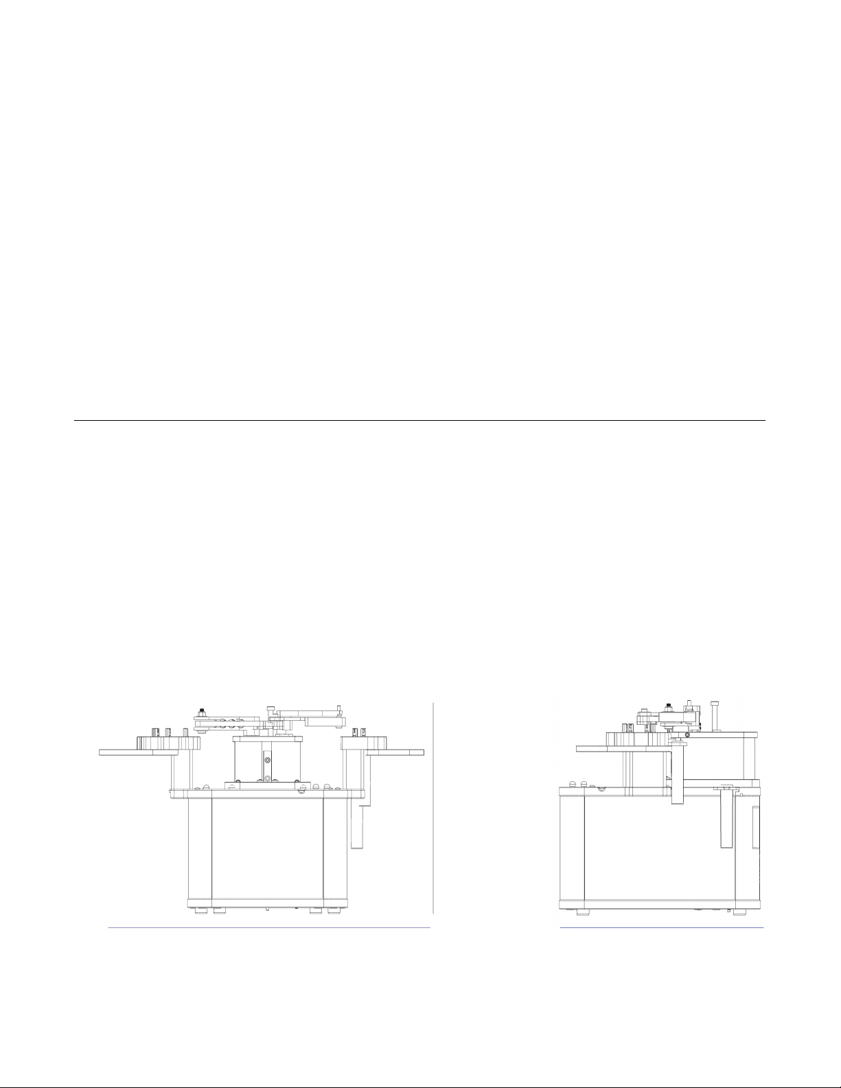
MANTIS
●Width: 354 mm or 13.9” (smaller without ACC or reagent holders)
●Height: Full Extension: 226 mm or 8.9” (not including pipette tip input)
●Height: No Extension: 193 mm or 7.6” (not including pipette tip input)
●Depth: 212 mm or 8.3”
Specifications
Chapter 3
Physical Dimensions
Front Side
226 mm
354 mm 212 mm
6
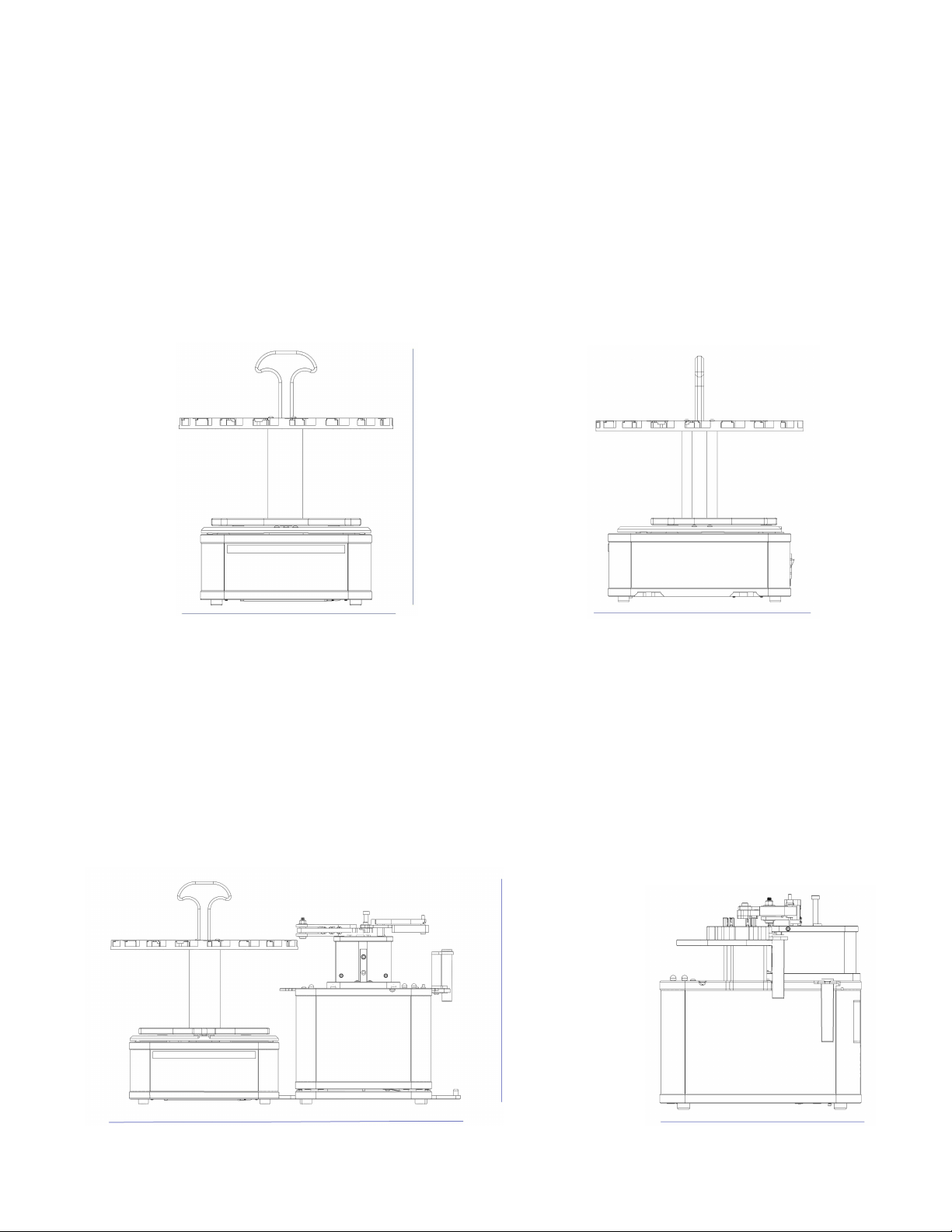
Large Capacity Chip Changer (LC3)
●Width: 240 mm or 9.4”
●Height: Full Extension: 284 mm or 11.2”
●Height: No Carousel: 88 mm or 3.5”
●Depth: 240 mm or 9.4”
Front Side
MANTIS User's Guide | Chapter 3: Specifications
MANTIS with Large Capacity Chip Changer (LC3)
●Width: 449 mm or 17.7” (MANTIS with LC3)
●Height: Full Extension: 284 mm or 11.2” (not including pipette tip input)
●Depth: 240 mm or 9.4”
Front Side
284 mm
240 mm 284 mm
449 mm
284 mm
240 mm

7
MANTIS User's Guide | Chapter 3: Specifications
The power supply for the system must meet or exceed electrical requirements of the
system to avoid damage and risk of fire.
●110 V - 240 V, 50 Hz - 60 Hz, 50 W typical, 150 W max
●Standard or European electrical outlet
Computer Requirements
●Computer OS: Windows XP Home Edition SP3 32-bit/Windows 7 Home Basic
64-bit/Windows Vista 32-bit/Windows 8/Windows 10
●1 open USB Port
●Dual Core 1 GHz processor
●At least 1 GB RAM
●1 GB Hard drive space
●768 pixels vertical minimum screen resolution
●.NET Framework 3.5
●FTDI 2.08.24
Electrical Requirements

8
Extremely Low Dead Volumes
To minimize dead volume, the ingredient plugs directly into the microfluidic chip. Dead
volumes can be reduced to 6 µL by using pipette tips as ingredient reservoirs. This feature
is ideal for dispensing even the most precious samples.
Optional Chip Changer
MANTIS can automatically dispense up to six reagents, allowing you to dispense complex
plates and assay development experiments.
Small Footprint
They say good things come in small packages, and the MANTIS is no different. The
MANTIS is the smallest liquid handling robot made by FORMULATRIX and boasts one of
the smallest footprints on the market.
With a base that fits on a standard mouse pad, the MANTIS can fit in nearly any workspace
while remaining robot accessible for automation.
Continuous Flow Dispensing (optional)
With optional continuous flow, the MANTIS can pressurize an external bottle to dispense
liquids at a constant dispense speed. This dispensing method allows for filling seven times
faster (at a rate of 150 µL/second) than the previous MANTIS. This increased dispensing
speed is suitable for filling deep well blocks.
Overview
Chapter 4
Key Features

9
Dual Wash Stations
The dual wash stations built into the MANTIS allow for easy sterilization during dispenses.
One station can be used for bleach or acceptable sterilization solutions for sterilization,
while the second station contains water for a final rinse.
The 3-step wash option is also available for a more thorough way to sterilize the MANTIS
chips using both water and wash solution. When you select this option, the MANTIS will
always wash its liquid lines with water, then wash solution, then rinse again with water.
Extended Plate Height Clearance for Deep Well Blocks
The dispense head of the MANTIS has clearance of up to 54 mm for dispensing into deep
well blocks.
Patented Microfluidic Dispensing Technology
At the core of the MANTIS is a patented microfluidic valve cluster that can measure and
dispense discrete volumes of liquid. Pressure and vacuum are used to open and close
each valve on the silicone valve cluster. This chip has two micro-diaphragms (100 nL / 500
nL or
1 µL / 5 µL depending on the chip option) that can fill and dispense as fast as 10 times per
second.
Integrated Ingredient Holders (optional)
The MANTIS comes fitted with removable ingredient holders that allow ingredients in 50
mL falcon tubes to sit safely during the dispense with no need for additional racks or risk
of tipping/spilling.
MANTIS User's Guide | Chapter 4: Overview

10
MANTIS FRONT
Hardware Overview
Chapter 5
MANTIS Components
Arms The MANTIS arms control the hand movements when
dispensing, loading and unloading chips.
Hand The hand holds the High Volume (HV), Low Volume (LV), High
Volume PFE, Low Volume PFE, or High Volume Continuous
Flow (CF) chip during general operations.
Chip Changer
Tube Holders
Plate Holder
Plate Clamp
Arm
Hand
MANTIS Front View
11
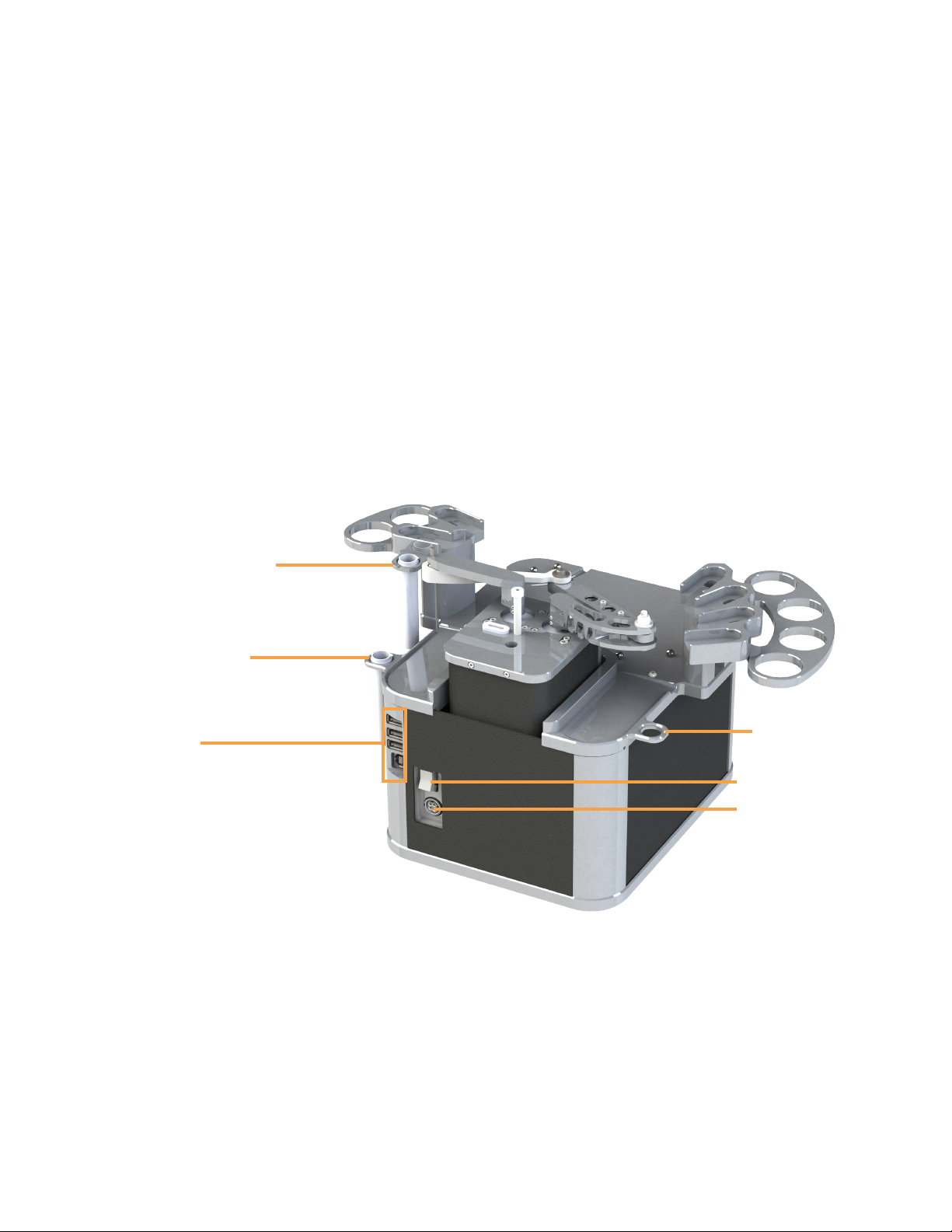
MANTIS BACK
Chip Changers Using the chip changers, the MANTIS can automatically dispense up
to six reagents without user intervention. The chip changers are
compatible with High Volume (HV), Low Volume (LV), High Volume
PFE, Low Volume PFE, or High Volume Continuous Flow (CF) chips.
Plate Clamps
Located on the lower-right of the plate holder, the plate clamps align
and secure the plate during the dispensing process.
Plate Holder The plate holder is compatible with almost all SBS plate types and
deep well blocks.
Tube Holder The tube holders are compatible with 50 mL Falcon tubes that are
ideal for large volume dispenses or frequently used reagents.
Waste Station The waste station is a station for the MANTIS to deposit waste
liquids.
Wash Stations The wash stations are where the MANTIS hold wash solutions and
water, used during the chip washing process. If you are running 3-
step Wash, wash solution should go in Wash Station 2, on the right
side of the MANTIS with the two chip stations. Otherwise, it can go in
Wash Station 1.
MANTIS User's Guide | Chapter 5: Hardware Overview
MANTIS Back View
Waste Station
Wash Station 1
Wash Station 2
USB Ports
Power Switch
Power Port

12
USB Ports The USB ports are where you plug the USB flash drive into the
MANTIS. Two of these ports are included for future expansion. The
last USB port (located at the bottom) is used for connecting the
MANTIS hardware to your computer. The other end of the USB
cable should be plugged into your computer.
Power Switch The power switch turns the MANTIS on and off.
Power Port The power port is the area where you plug the power cable into the
MANTIS.
MANTIS User's Guide | Chapter 5: Hardware Overview

13
Setting up the MANTIS for initial use means connecting all of the cables, setting up the
wash and waste tubes and installing the .NET framework as well as the FTDI drivers to
your computer.
To set up the MANTIS for initial use:
1. Connect the power cable to the MANTIS and plug it into an available outlet.
2. Make sure the power supply adapter is ON. Find the switch at the back of the
power supply adapter.
3. Connect the USB cable to the MANTIS and plug it into your computer.
4. Find the power switch at the back of the MANTIS and turn the MANTIS ON.
5. Once your computer detects the MANTIS, open Windows Explorer and locate
the MANTIS USB drive. Look for MANTIS-XXXX (the X’s represent your serial
number).
6. Double-click the MANTIS USB drive to display its contents.
●Double-click the Prerequisites folder. You will see the dotNET and
CDM20824_Setup.exe (FTDI driver). Install the dotNET driver and the FTDI
driver. You will be asked to restart your computer once you install the FTDI
driver.
●If you would like to have a shortcut for the MANTIS software on your
desktop, open the MANTIS folder, then open the Bin folder. Right-click the
MANTIS software icon , then point to Send to and select Desktop
(create shortcut).
Initial Setup
Chapter 6
Setting Up the MANTIS

14
The shortcut is dependent upon the drive letter dictated by the MANTIS USB
connection. If at any time you disconnect the MANTIS and plug it into a
different USB port, the original desktop shortcut will no longer work.
Plate definitions are the files that define the geometry of the labware to the MANTIS.
Having a correct plate definition can be an important factor influencing the outcome of a
dispense. Four plate definitions (including one for a circular plate) come pre-installed with
the MANTIS software for your convenience, however, depending on the types of plates
you use you may need to add new plate definitions or modify existing plate types. You
must have at least one plate defined in MANTIS software before you can design a
dispense.
If you want to add a new plate to the plate library, please follow the instructions below
under Adding a New Plate Type on page 14.
If you want to modify an existing plate type in the plate library, please follow the
instructions under Modifying an Existing Plate Type on page 20.
If you are defining or modifying the definition of a circular plate, please see Adding
Circular Plates to the Plate Type Library on page 23.
Adding a New Plate Type
Prerequisites
●You have prepared a reagent for the test drop.
●You have attached the tube input adapter on the chip. Ignore this prerequisite if
you are using a pipette tip.
●You have attached a chip to the MANTIS hand.
To add a new microplate to your plate library:
1. On the Tools menu, click Plate Type Editor.
2. Go to the File menu, select New, and then select Rectangular Plate. This will
start the new plate type wizard.
Adding Plate Types to the Plate Type Library
Note: You can use the keyboard keys to control the MANTIS arms
motion when adding or modifying plate types.
W: The key moves the MANTIS arms backward along the Y Axis.
S: The key moves the MANTIS arms forward along the Y Axis.
A: The key moves the MANTIS arms left along the X Axis.
D: The key moves the MANTIS arms right along the X Axis.
R: The key moves the MANTIS arms upward along the Z Axis.
F: The key moves the MANTIS arms downward along the Z Axis.
Note: To add a circular plate, see Adding Circular Plates to the Plate Type
Library on page 23.
MANTIS User's Guide | Chapter 6: Initial Setup
15
MANTIS User's Guide | Chapter 6: Initial Setup
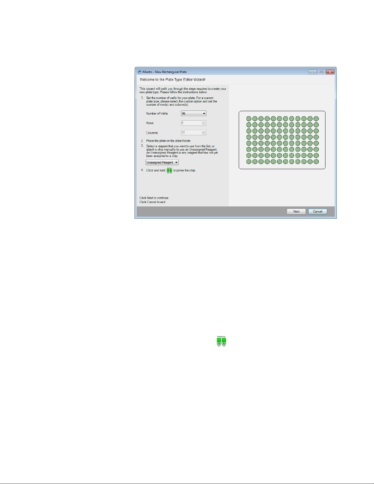
3. On the wizard, select the Number of Wells from the list of typical SBS well
numbers or if you want to add a custom plate, select Custom and set the number
of rows and columns.
4. Place your new plate on the plate holder.
5. MANTIS needs to pick up a chip in order to proceed with the plate tuning
procedure. The reagent assigned to that chip can optionally be used to dispense
test drops while tuning your plate. Choose one of the following options:
●Select a reagent from the Select Reagent list to use that chip for the
plate tuning procedure. MANTIS will automatically attach the assigned
chip to the MANTIS hand.
●Select Unassigned Reagent if you want to use a reagent that has not
been assigned to a particular chip. When you use an unassigned reagent,
you must manually attach the desired chip to the MANTIS hand. Make
sure you have prepared a bottle or pipette tip containing the desired
reagent if you want to dispense test drops during the procedure.
6. Click and hold the prime button to prime the chip and then click Next.
Plate Type Editor Wizard

16
MANTIS User's Guide | Chapter 6: Initial Setup
7. Set the top-left well position by clicking the arrows, or use keyboard keys to
control the MANTIS hand to aim the nozzle tip at the top-left well. Then click the
Dispense button to dispense the test drop. If you are satisfied with the position,
click Next.
8. Set the bottom-left well position by clicking the arrows or use keyboard keys to
control the MANTIS hand to aim the nozzle tip at the bottom-left well. Then click
the Dispense button to dispense the test drop. If you are satisfied with the
position, click Next.
9. Set the top-right well position by clicking the arrows or use the keyboard keys to
control the MANTIS hand to aim the nozzle tip at the top-right well. Then click the
Dispense button to dispense the test drop. If you are satisfied with the position,
click Next.
10. Set the bottom-right well position by clicking the arrows or use the keyboard keys
to control the MANTIS hand to aim the nozzle tip at the bottom-right well. Then
click the Dispense button to dispense the test drop. If you are satisfied with the
position, click Next.
Note: For best results leave approximately 2 mm clearance between the top of
the plate and the chip nozzle.
Top-Left Position Settings
Table of contents
Popular Industrial Equipment manuals by other brands

ABB
ABB HT613210 Operation manual

CHART
CHART Nomad 830G MP product manual

ZKTeco
ZKTeco OP1000 Series user manual

PCB Piezotronics
PCB Piezotronics 352A24/NC Installation and operating manual

OP
OP TUBOMATIC H79 EL Use and maintenance manual

Grundfos
Grundfos IMpress Installation, operation and maintenance manual


