02/13 Rev. 5.08-01 OPERATING INSTRUCTIONS Commissioning & Operation
DPM – PEM
9
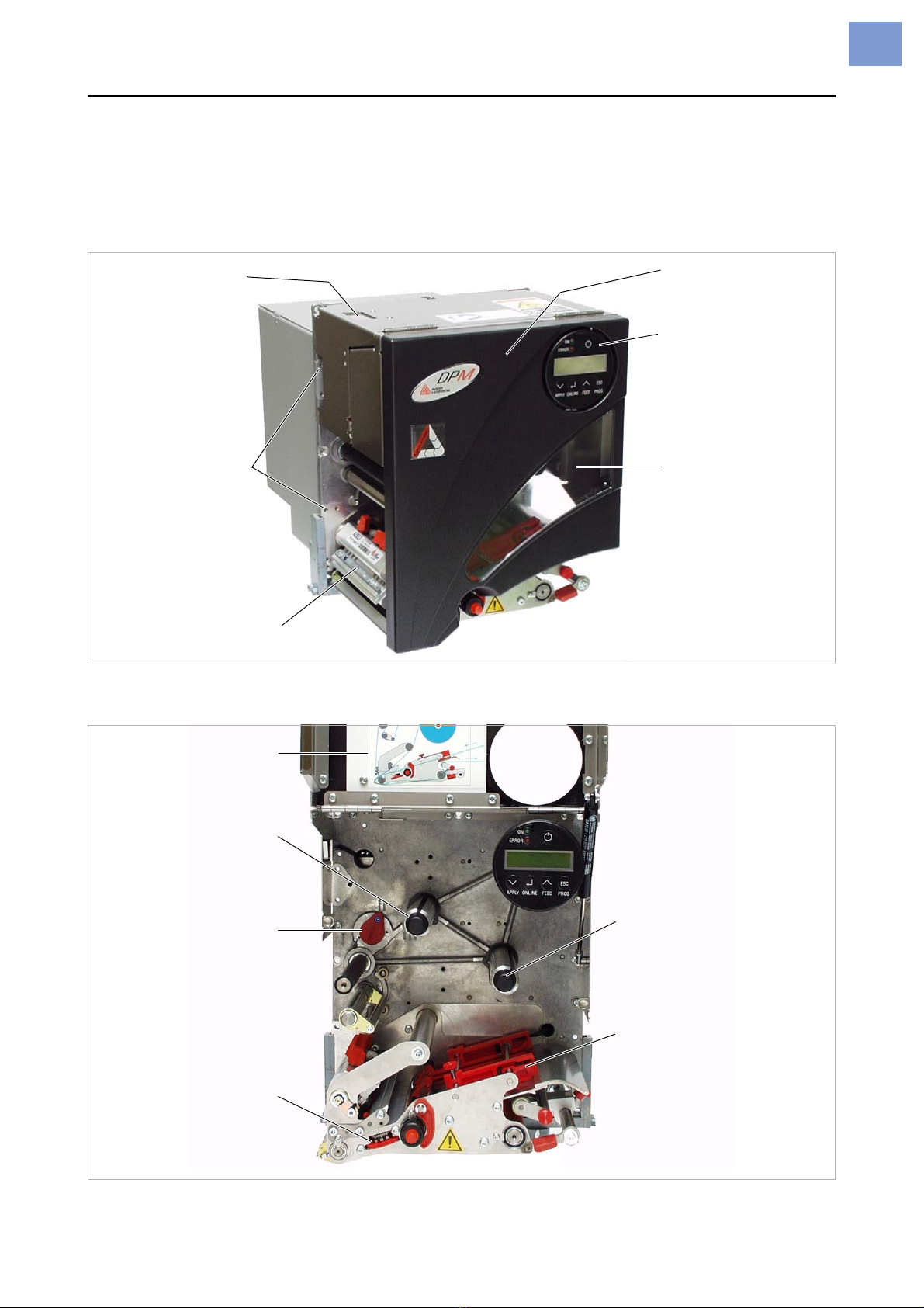
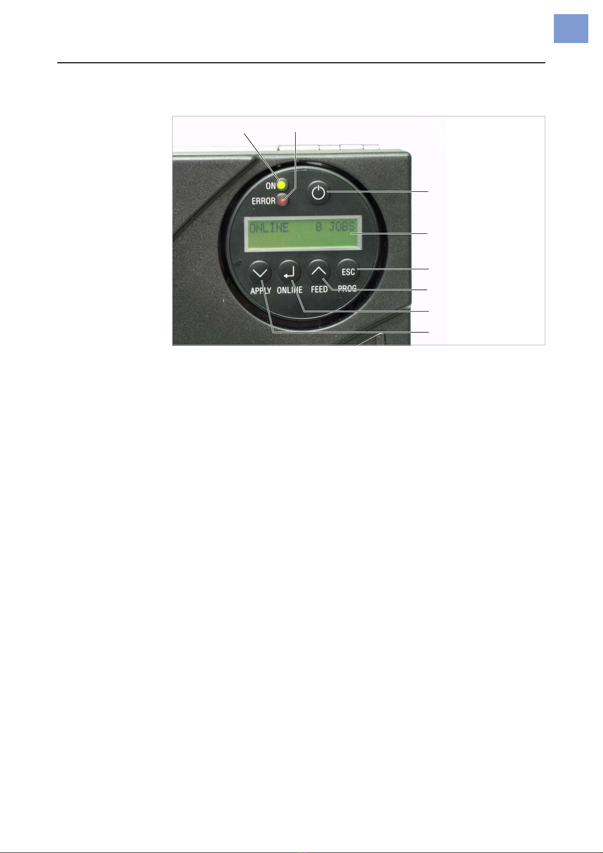
Control panel (display)
[4] DPM/PEM control panel.
Power indicator Lights up green, when the printer is switched on.
Error indicator Lights up red, when the printer is in message mode.
Display With 32 digits and two lines, the display shows the operating conditions (mo-
des) for parameters, values, status and errors. You can select the language
you want to use for the display. Backlighting ensures good legibility.
Button functions The buttons offer a multitude of operating functions. A logical menu structure
is used for operation. The meaning of each button varies according to the
operating mode and the menu item. Additionally, special functions have been
programmed for certain button combinations.
Depending on the modes and menu levels, the following functions apply for
each button:
On/Off button Switches the device on or off. To reach this, hold the button longer than 2
seconds pressed. Precondition: The mains switch must be switched on (po-
sition „I“, see chapter Connections / on page 7).
Online button •For switching between online and offline mode.
•For confirming entries, menu items and messages.
•For selecting print jobs and for entering values in standalone mode.
Apply button •Triggers the application process. Requirements:
– Applicator fitted and activated
– Printer offline.
•Also for accessing deeper levels within the menu structure and selecting
menu items.
•For decrementing values.
Display
Power indicator Error indicator
On-off switch
Prog button
Feed button
Online button
Apply button