HBK C16M User manual

C16M
ENGLISH DEUTSCH ESPAÑOL
Mounting Instructions
Montageanleitung
Instrucciones de montaje

Hottinger Brüel & Kjaer GmbH
Im Tiefen See 45
D-64293 Darmstadt
Tel. +49 6151 803-0
Fax +49 6151 803-9100
www.hbkworld.com
Mat.: 7-2001.0078
DVS: A01268 04 XS0 01
02.2022
EHottinger Brüel & Kjaer GmbH
Subject to modifications.
All product descriptions are for general information
only. They are not to be understood as a guarantee of
quality or durability.
Änderungen vorbehalten.
Alle Angaben beschreiben unsere Produkte in allge
meiner Form. Sie stellen keine Beschaffenheits- oder
Haltbarkeitsgarantie dar.
Reservado el derecho a modificaciones.
Todos los datos describen nuestros productos de
manera general. No representan ninguna garantía de
calidad o de durabilidad.
C16M
ENGLISH DEUTSCH ESPAÑOL
Mounting Instructions

C16M
TABLE OF CONTENTS
2
TABLE OF CONTENTS
1 Safety instructions 3................................................
2 Markings used 5....................................................
2.1 The markings used in this document 5.................................
2.2 Symbols on the product 5............................................
3 General 6..........................................................
4 Mounting instructions 7.............................................
5 Mounting 8........................................................
6 Connection 9.......................................................
6.1 Parallel connection of several weighing modules 9.......................
6.2 Connections using the four‐wire technique 10............................
6.3 Cable extensions 10..................................................
7 Operation 11........................................................
8 Dimensions 12......................................................
8.1 Mounting example for weighing modules with stay rods 15.................
9 Specifications 16....................................................
10 Accessories, to be ordered separately 17...............................
10.1 Scope of delivery 17..................................................

3
C16M
SAFETY INSTRUCTIONS
1 SAFETY INSTRUCTIONS
In cases where a breakage would cause injury to persons or damage to equipment, the
user must take appropriate safety measures (such as fall protection, overload protection,
etc.). For safe and trouble‐free operation, weighing modules must not only be correctly
transported, stored, sited and installed but must also be carefully operated and main
tained.
It is essential to comply with the relevant accident prevention regulations. In particular
you should take into account the limit loads quoted in the specifications.
Use in accordance with the regulations
C16M... type weighing modules are conceived for weighing applications. Use for any
additional purpose shall be deemed to be not in accordance with the regulations.
In the interests of safety, the weighing modules should only be operated as described in
the Mounting Instructions. It is also essential to observe the appropriate legal and safety
regulations for the application concerned during use. The same applies to the use of
accessories.
The weighing modules are not safety elements within the meaning of its use as intended.
Proper and safe operation of this load cell requires proper transportation, correct
storage, assembly and mounting and careful operation and maintenance.
General dangers due to non‐observance of the safety instructions
The weighing modules correspond to the state of the art and are fail‐safe. The weighing
modules can give rise to residual dangers if they are inappropriately installed and
operated by untrained personnel.
Everyone involved with the installation, commissioning, maintenance or repair of a force
transducer must have read and understood the Mounting Instructions and in particular
the technical safety instructions.
Residual dangers
The scope of supply and performance of the weighing modules covers only a small area
of weighing technology. In addition, equipment planners, installers and operators should
plan, implement and respond to the safety engineering considerations of weighing
technology in such a way as to minimise residual dangers. Prevailing regulations must be
complied with at all times. There must be reference to the residual dangers connected
with weighing technology.

C16M
SAFETY INSTRUCTIONS
4
Environmental conditions
In the context of your application, please note that all materials which release chlorine
ions will attack all grades of stainless steel and their welding seams. In such cases the
operator must take appropriate safety measures.
With environmental conditions that cannot be clearly defined, HBK recommends to pro
vide the load cells and weighing modules with a protective coating which matches these
conditions (after mounting) in order to prevent the influence of aggressive media. Please
take into account the resistance of the cable material and the mounting parts.
Prohibition of own conversions and modifications
The weighing modules must not be modified from the design or safety engineering point
of view except with our express agreement. Any modification shall exclude all liability on
our part for any damage resulting therefrom.
Qualified personnel
These weighing modules are only to be installed by qualified personnel strictly in
accordance with the technical data and with the safety rules and regulations which
follow. It is also essential to observe the appropriate legal and safety regulations for the
application concerned. The same applies to the use of accessories.
Qualified personnel means persons entrusted with the installation, fitting, commissioning
and operation of the product who possess the appropriate qualifications for their
function.
Accident prevention
Although the specified nominal capacity in the destructive range is several times the full
scale value, the relevant accident prevention regulations from the trade associations
must be taken into consideration.
5
C16M
MARKINGS USED
2 MARKINGS USED
2.1 The markings used in this document
Important instructions for your safety are specifically identified. It is essential to follow
these instructions in order to prevent accidents and damage to property.
Symbol Significance
CAUTION This marking warns of a potentially dangerous
situation in which failure to comply with safety
requirements can result in slight or moderate physical
injury.
Notice This marking draws your attention to a situation in
which failure to comply with safety requirements can
lead to damage to property.
Important This marking draws your attention to important in
formation about the product or about handling the
product.
Tip This marking indicates application tips or other
information that is useful to you.
Information This marking draws your attention to information
about the product or about handling the product.
Emphasis
See …
Italics are used to emphasize and highlight text and
identify references to sections, diagrams, or external
documents and files.
2.2 Symbols on the product
CE mark
The CE mark enables the manufacturer to guarantee that the
product complies with the requirements of the relevant EU direc
tives (the declaration of conformity is available at
http://www.hbm.com/HBMdoc
).

C16M
GENERAL
6
3 GENERAL
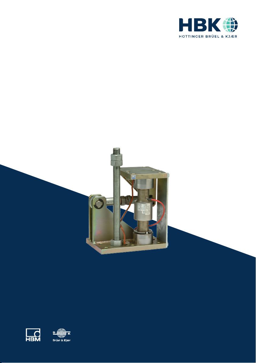
HBK supplies C16M... weighing modules for max. capacities 20 t up to 200 t. The tank
weigh modules are mainly designed for tank weighing applications and manufactured
completely from galvanized steel or stainless steel.
The tank weigh modules are fitted with integral transverse retention guides which can
absorb horizontal forces, such as occur for example with tanks used with stirring mecha
nisms or by wind forces. Optionally, a simple anti‐liftoff device may be installed by the
user.
The modules are formed from a lower module plate for fastening to the foundation
frame, the load cell with load transfer elements and the upper module plate for mounting
an the tank. A rocker pin is used for the load transfer which provides compensation for
horizontal offsets in the applied load (in direction perpendicular to transverse retention
guides as, for example, can arise through thermal strain). The weighing modules are pre‐
assembled and supplied with transport safety retainers.

7
C16M
MOUNTING INSTRUCTIONS
4 MOUNTING INSTRUCTIONS
Slt should be ensured that the mounting/siting surfaces are clean, flat and level. De
pending on the Installation circumstances, any levelling error can be compensated for
example by suitable wedges and compensating plates (permanently welded) or by the
grinding away the mounting surface. On no account must the module plates be
ground.
Notice
On no account must the module plates be ground.
SThe foundation/base frame must be sufficiently stiff so that no impermissible de
formations (e.g. deflections) occur on loading.
SIn order to keep the mounting as free of straining forces as possible, the fastening
holes on the base frame and the tank joint must be sufficiently in alignment. Same
means to the bore of the anti‐liftoff device.
SUniform loading on the support points should be provided where possible. Correct
adjustment of the height on the supporting points must be ensured (have compensat
ing shims ready). This is especially important for statically undefined supports.

C16M
MOUNTING
8
5 MOUNTING
Slt should be ensured when mounting the tank that, for example, no shock loads are
applied to the module when lowering it onto the supports. Even short‐term loads
which exceed the load cell limits can lead to damage.
SWith heavy tanks or unfavorable Installation conditions the use of mounting aids (aux
iliary supports, jack equipment) is recommended.
SThe mounting plate and upper module plate should be firmly fastened to the founda
tion, respectively the tank joint.
SThe weighing modules should be mounted such that they are free of transverse forces
in the initial state. This means that the mounted rocker pin load cell must be lined up
as near to the perpendicular as possible. This is the case when the foundation and
tank Joint are horizontal and the mounting holes on the foundation and the tank are
sufficiently aligned. As supplied, the transport locking plate is fitted such that this is
the case, thus allowing hole patterns to be checked easily.
SA anti‐liftoff device can be effected by screwing in a threaded rod of an appropriate
length and checking with a nut in the lower module plate. The threaded rod must have
a working clearance in a though hole of the vessel base. Two further nuts are to be
checked over a washer with approx. 2 mm working clearance relative to the vessel
base.
SAs protection against welding currents that can damage parts of the transducer, it is
recommended that the EEK4 Earthing Cable is used (included in the supply).
SWith statically undefined supports, non‐uniform loading of the modules occurs due to
flexibility as the Ioad is taken up or due to inadequate accuracy in the height adjust
ment. This non‐uniformity should be checked an the individual Ioad cells by applying
an excitation voltage and comparing the Output voltages. To prevent overloads, large
non‐uniformities should be compensated by inserting shims under those supports
which are least loaded.
SThe optional cable with an outer braided wire covering for the configurable K-Z16A3
with option 20R, is intended for use when there is increased mechanical stress (e.g.
damage caused by gnawing rodents). If this cable is used, the outer braided wire has
to be connected to potential equalization at least once, to avoid accidental energiza
tion. This outer braided wire is not used to shield the load cell. The inner braid of the
load cell cable is used for shielding.
9
C16M
CONNECTION
6 CONNECTION
Strain‐gauge based Ioad cells can be connected to:
Scarrier frequency or
SDC‐measuring amplifiers.
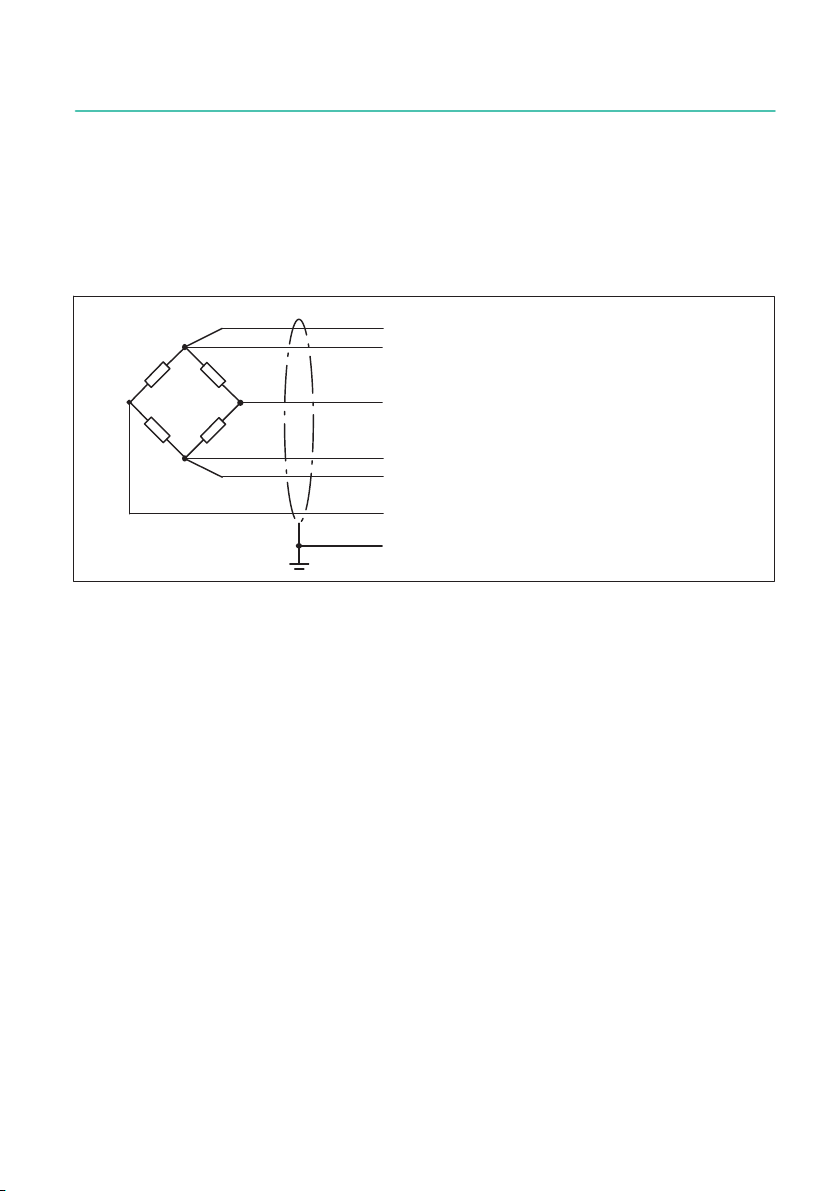
The transducer connection is implemented using the six‐wire technique. The connection
assignment can be taken from the following illustration.
wh (white)
bk (black)
gy (grey)
Shield connected with housing
gr (green)
rd (red)
ye (yellow)
Excitation line (-)
Sensor line
Signal line (+)
bu (blue)
Sensor line
Signal line (-)
Excitation line (+)
Fig. 6.1 Wiring code (6‐wire‐technique)
Electrical and magnetic fields often induce interference voltages in the measurement
circuit.
Therefore:
SUse screened low‐capacitance measurement cables only (HBK cables satisfy this cri
terion).
SDo not route the measuring cable parallel to power and control lines. If this is not pos
sible, protect the measurement cable, e.g. with steel conduit.
SAvoid the stray fields of transformers, motors and conductors.
6.1 Parallel connection of several weighing modules
Transducers can be wired in parallel by joining the transducer cable core ends of the
same color. In this case HBK program offers the junction boxes VKK... and for use in Ex
areas the junction box VKK...EX. The output signal of these junction boxes is the an aver
age of the single output signals.

C16M
CONNECTION
10
CAUTION
Overloading in a single load cell can no longer be detected from the output signal.
6.2 Connections using the four‐wire technique
With connections to amplifiers using the four‐wire technique the cores BU (blue) and GN
(green) should be connected together, as should BK (black) and GR (grey). Please take in
account that this causes deviations to the sensitivity and the temperature coefficient of
sensitivity that this causes.
6.3 Cable extensions
Cable extensions must be screened and of low capacitance. We recommend the use of
HBK cables which satisfy these requirements. With cable extensions it should be ensured
that a proper connection is provided with low contact resistances and good insulation.
When using the six‐wire technique, the effects of resistance changes in the extension
cable are compensated. If you extend the cable with the four-wire technique, the sensitiv
ity deviation can be rectified by adjustment. Temperature effects though are only com
pensated with the operation using the six-wire technique.
The load cell connecting cable should be routed so that any condensed water or damp
ness forming on the cable can drip off. lt must not be led to the load cell. In addition, it
must be ensured that no dampness can penetrate the open end of the cable.

11
C16M
OPERATION
7 OPERATION
STransverse forces during operation, which do not act in the direction of the guide arm,
should be avoided.
SThe play on the transverse guide arm should be checked regularly and adjusted if nec
essary.
SThe play in the tank removal lock should be set to 2 mm.
SThe weighing modules without tank removal lock should not be completely relieved of
the Ioad (the load transfer elements lift off).

C16M
DIMENSIONS
12
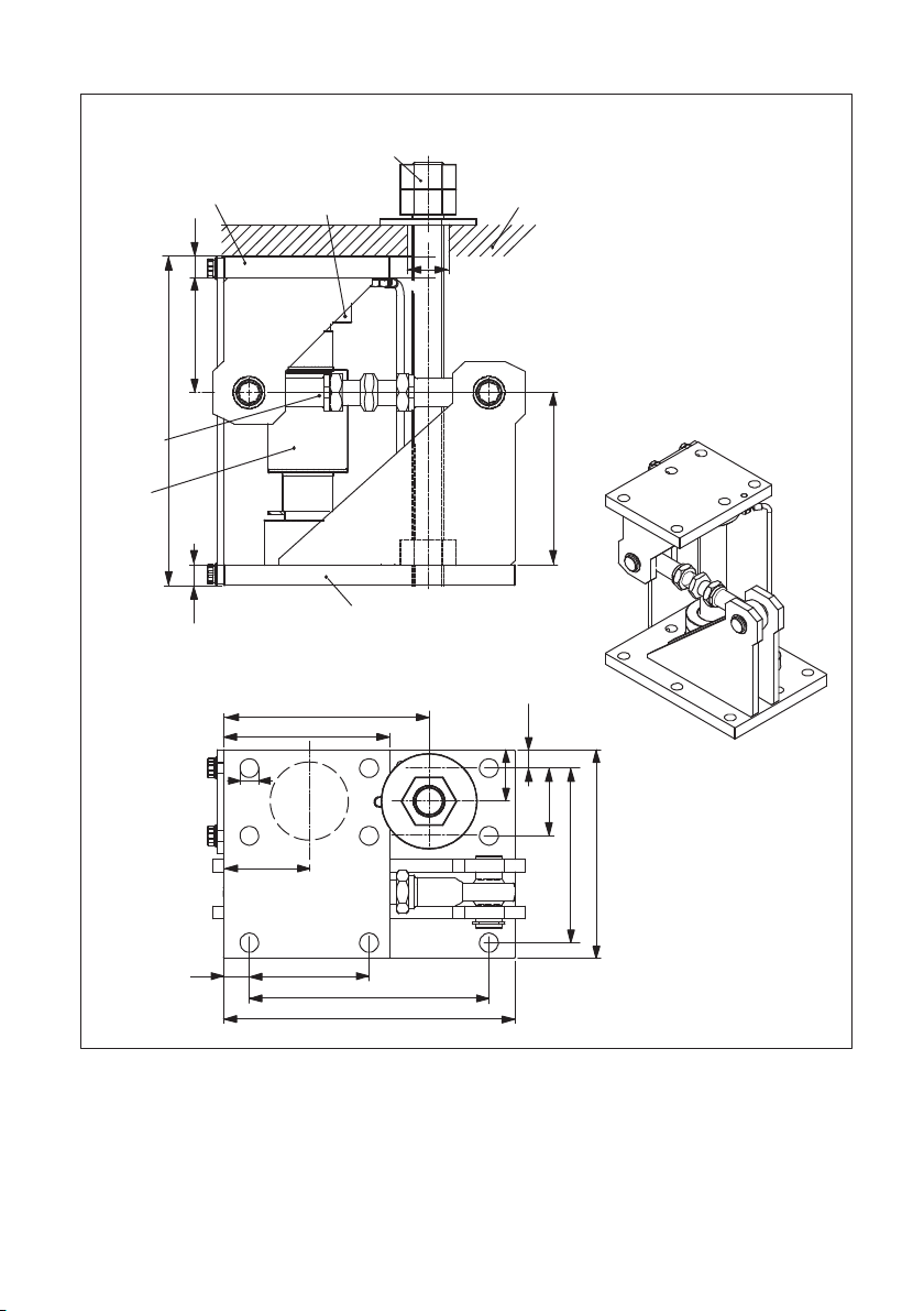
8 DIMENSIONS
222.5
130
15
15
Tank foot
Accessory
1‐ZAC16/MSL(R)40T
Lower module plate
Thrust piece
Upper module plate
Stay rod
C16A/...
∅28
Top view, drawing without tank foot
* Threat for alternative mounting of the anti‐liftoff device (accessory)
C16/M1LB20 t ... 40 t
Drawing without anti‐liftoff
device
280
160
230
115
25
32.5
65 17.5
167.5
200
18
196
88
M20*
Dimensions in mm
(1 mm = 0.03937 inches)
13
C16M
DIMENSIONS
Top view, drawing without tank foot
C16/M1LB60 t
50
197.5
82.5
Ø18
25 115
230
160
17.5
65
167.5
200
280
Stay
rod
Lower module plate
∅40
C16A...
110
315
Upper module plate Thrust piece
Accessory
1‐ZAC16/MSL60T
Tank foot
20
20
165
Dimensions in mm
(1 mm = 0.03937 inches)

C16M
DIMENSIONS
14
C16/M1LB100 t + 200 t
110
165
400
35165
60280
Accessory
1‐ZAC16/MSL100T
Upper module plate
Thrust piece
Tank foot
Stay rod
35 230
330
300
150
Ø22
Top view, drawing without foot tank
Ø50
Lower module plate
100 30
30
380
C16A...
420
350 Dimensions in mm
(1 mm = 0.03937 inches)
15
C16M
DIMENSIONS
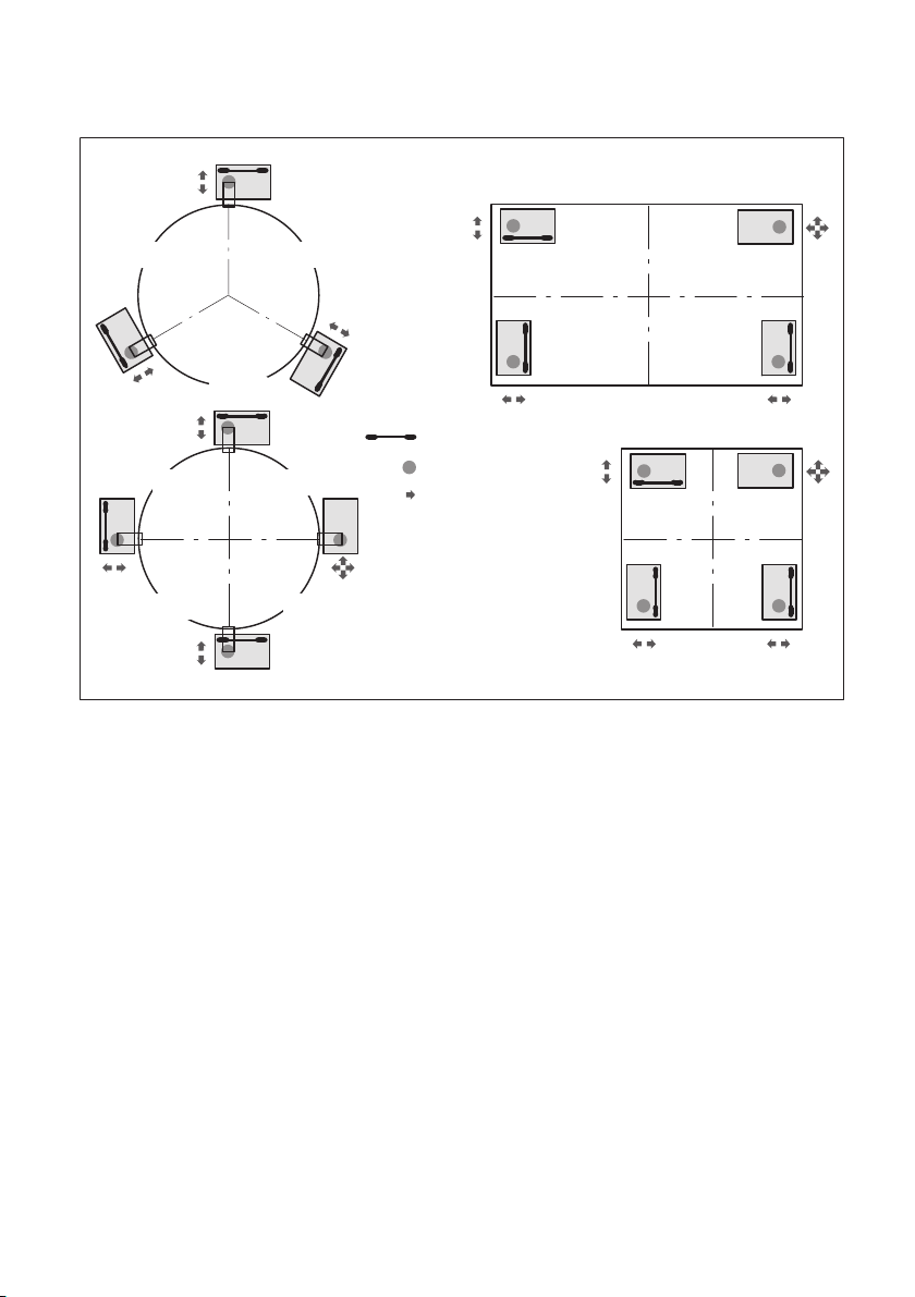
8.1 Mounting example for weighing modules with stay rods
Stay rod
Load introduction
Degree of freedom
120°120°
120°
90°90°
90°90°
Attention:
The represented bearing ar
rangements consider only
weighing‐technical criteria.
The carrying and stability
must be examined and guar
anteed in each case by the
operator.
C16M
SPECIFICATIONS
16
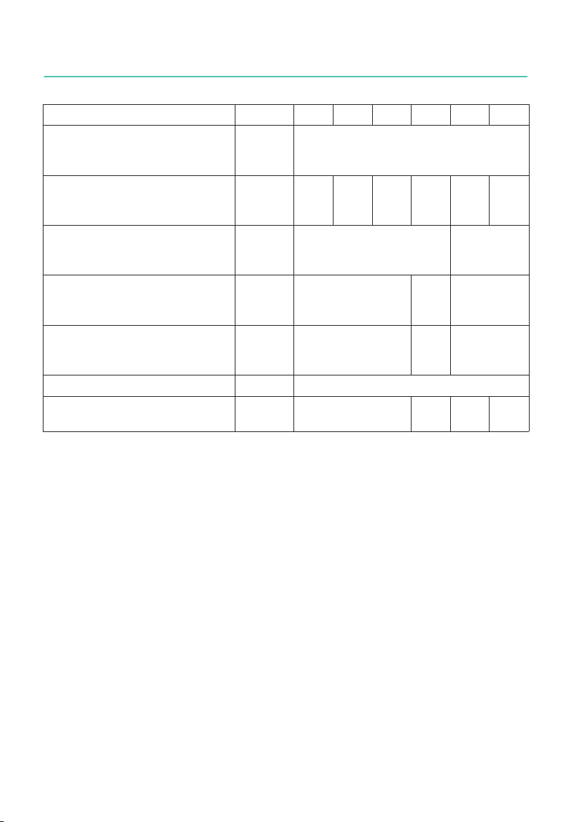
9 SPECIFICATIONS
Maximum capacity t 20 30 40 60 100 200
Limit load % of
max.
capacity
150
Restoring force, at 1 mm side
offset vertically to the stay rod
direction
% of
applied
load
0.49 0.76 0.94 0.52 0.48 0.81
Maximum permissible side off
set transverse to the stay rod
axis
mm ±4.0 ±5.0
Maximum permissible
horizontal force in the stay rod
direction
kN 50 100 150
Max. permissible lifting force
when a anti‐liftoff device is
used1)
kN 80 120 240
Material stainless steel or galvanized
Weight, approx. (depending on
the version, incl. load cells)
kg 20 55 105 107
1) An anti‐liftoff device, for example a threaded rod (please see accessories), can be mounted in the
assigned threaded hole.

17
C16M
ACCESSORIES
10 ACCESSORIES, TO BE ORDERED SEPARATELY
Each for two weighing modules (see Dimensions):
1-ZAC16/MSL40T, for C16/MSL20 t...40 t, consists of:
1 piece threaded rod M20x10001), galvanized
6 pieces hexagonal nut M20 DIN 934, galvanized
2 pieces washer DIN 9021, ∅21 mm, galvanized
1-ZAC16/MSLR40T, for C16/MSLR20 t...40 t, consists of:
1 piece threaded rod M20x10001), stainless steel
6 pieces hexagonal nut M20 DIN 934, stainless steel
2 pieces washer DIN 9021, ∅21 mm, stainless steel
1-ZAC16/MSL60T, for C16/MSL60 t, consists of:
1 piece threaded rod M30x10001), galvanized
6 pieces hexagonal nut M30 DIN 934, galvanized
2 pieces washer DIN 9021, ∅31 mm, galvanized
1-ZAC16/MSL100T, for C16/MSL100 t + 200 t, consists of:
4 pieces threaded rod M30x10001), galvanized
12 pieces hexagonal nut M30 DIN 934, galvanized
4 pieces washer DIN 9021, ∅31 mm, galvanized
Further accessory
Fixed bearings with the same installation height as the weighing module are e.g. very
helpful as a dummy for installations. Please find further information in a separate data
sheet.
10.1 Scope of delivery
Weighing module complete mounted with stay rod, thrust pieces, ground wire and load
cell.
1) The threaded rods have to be adapted to the corresponding installation conditions on the customer
side.

C16M
ACCESSORIES
18
Table of contents
Languages:
Other HBK Industrial Equipment manuals


