FORNI Gennarino 100 E User manual

www.stefanoferraraforni.it
Stefano Ferrara Forni S.R.L.
Forni a legna artigianali
Neapolitan handmade brick ovens
Via Provinciale Pianura,2 – int.12
80078 Pozzuoli, Napoli
Tel./Fax: +39 081 876 1664
e-mail: info@stefanoferraraforni.it
P.IVA 06771801211
C.C.I.A.A. 838246
ELECTRIC OVEN
INSTALLATION AND OPERATING MANUAL
Gennarino 100 E
PLEASE READ ALL INSTRUCTIONS BEFORE INSTALLING AND USING
THE APPLIANCE

www.stefanoferraraforni.it
2
- Introduction .............................................................................................................................................. 3
- Installation operating and maintenance preface ............................................................................................. 5
- Features ................................................................................................................................................... 6
- Instruction for lifting and moving oven ………………………………….... ....................................................... 7
- Packaging removing …………………………………. .................................................................................. 9
- Assembly the support stand……………………………………………………… ........................................ 9
- Placement of the oven on the support stand……………………………………………………… ............... 10
- Installation procedures
General information …………………………………………………………………………..... ........... 11
Installation of components box and front panel for housing control unit display… ...................... 12
Marble shelf placement………………………… ............................................................................ 14
- Electrical connections …………………………………………………………………………… .................... 15
- Electrical maintenance
Electrical power cord replacement…………………………………………………………………..... 16
Bulb replacement … ..................................................................................................................... 16
- Oven venting ........................................................................................................................................... 17
- Control unit .............................................................................................................................................. 18
User interface initial information………………………………………………………………..... ....... 18
First use… .................................................................................................................................... 18
Stand by screen………………………………………………………………..... ................................ 19
- Configuration ........................................................................................................................................... 19
Date and time………………………………………………………………..... ................................... 19
Languages … ............................................................................................................................... 20
- ON screen ............................................................................................................................................... 20
- Working temperature setting. .................................................................................................................. 21
- Top and floor power setting .................................................................................................................... 21
- Status bar ................................................................................................................................................ 22
- Screen saver .......................................................................................................................................... 25
- Alarm management ................................................................................................................................. 26
- Alarm codes ............................................................................................................................................. 27
- Control unit sizes .................................................................................................................................... 29
- Back side control unit .............................................................................................................................. 30
- Connectors .............................................................................................................................................. 31
- Control unit electrical connections ........................................................................................................... 32
www.stefanoferraraforni.it
3
INTRODUCTION
This manual has been made so that the user of the oven can work in complete safety.
THE USER HAS OBLIGATION TO READ CAREFULLY AND TO OBSERVE CAREFULLY THE
INSTRUCTIONS OF THE MANUAL.
Failure to comply with the instructions contained in this manual, means to operate in the conditions of use
not foreseen by the manufacturer.
THE MANUFACTURER IS NOT LIABLE FOR ANY DAMAGES CAUSED BY THINGS OR PERSONS,
DUE TO THE FAILURE TO OBSERVE THE INSTRUCTIONS AND THE RECOMMENDATIONS IN THIS
MANUAL.
The manual must be kept in good condition and must always be available for quick reference in case of
need.
THE MANUAL IS OF OWNERSHIP OF THE MANUFACTURER AND CANNOT BE REPRODUCED EVEN
PARTIALLY, AS WELL AS IT CANNOT BE DIFFUSED OR USED FOR ADVERTISING PURPOSE OR
SHARED WITH THIRD PARTIES.
ANY TRANSGRESSION WILL HAVE CIVIL AND PENAL SANCTIONS AS A CONSEQUENCE.
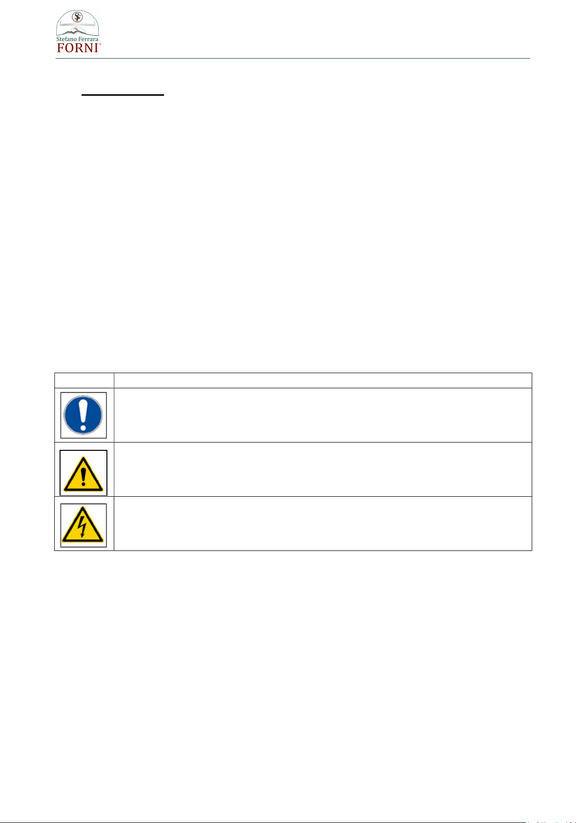
EXPLANATION OF SYMBOLS AND WARNINGS
SYMBOL DESCRIPTION
Symbol used to identify information of particular importance within the manual. The
information also concerns the safety of the personnel involved in the use of the
machine.
Symbol used to indicate passages of technical importance in the instructions and
warnings or procedures related to operator safety.
Symbol used to indicate warnings or procedures related to electricity.
NOTE ON THE PRODUCT
The aim of the manufacturing company is to make ovens that meet the current technical state. So we always
take care of our products even after delivery.
For any problems or inconveniences contact the service center:
Email: info@stefanoferraraforni.it - tel. +39 081 876 16 64

www.stefanoferraraforni.it
4
INTRODUCTION ABOUT INSTRUCTIONS OF WORKING
These instructions have the task of allowing and facilitating the safe and appropriate use of the OVEN and of
exploiting the regulatory use possibilities provided.
Their observance helps to avoid dangers, repair costs, to reduce off-duty times and to increase the lifespan
of the device.
Operating instructions are to be followed also taking in consideration the regulations on accident prevention
and environmental protection valid in the country of installation
BUYER'S OBLIGATIONS
The buyer is obliged to:
• Observe the national regulations concerning workplace safety;
• Observe the instructions contained in the manual.

www.stefanoferraraforni.it
5
INSTALLATION OPERATING AND MAINTENANCE PREFACE
WARNING !
READ THIS ENTIRE MANUAL BEFORE YOU INSTALL THE OVEN. FAILURE TO
FOLLOW INSTRUCTIONS MAY RESULT IN PROPERTY DAMAGE, BODILY INJURY, OR
EVEN DEATH.
When this oven is not properly installed, a fire may result. To reduce the risk of fire, follow the
installation instructions
Contact your local building or fire officials for clarification on any restrictions on installation of this oven
in your area, or need for inspection of the oven installation.
DO NOT close the oven door while a fire is in the oven.
Place the door over the oven opening after cooking is completed at the end of the work day.
Hot while in operation. Keep children, clothing and furniture away. Contact may cause skin burns.
Do not burn garbage or flammable fluids.
Smokes of the burning must be expelled through a flue system conform to the local rules.
Do not connect the oven to a chimney flue serving another appliance.
Keep children and pets away from hot oven.
DO NOT USE products not specified for use with this oven.
DO NOT USE liquid fuel (firelighter fluid, gasoline, lantern oil, kerosene or similar liquids) to start or
maintain a fire
DO NOT use water to dampen or extinguish fire in the oven.
Keep a proper extinguisher (class A) close to the oven at all times .
Instruct all personnel about location and use of the fire extinguisher and proper fire emergency
procedures.
DO NOT pack required air spaces with insulation or other materials.
In case of use of the oven with wood use only well dried wood.
In case of use of the oven with wood, use a metal shovel to remove the ashes and place them in a
metal bin with a tightly fitting lid. The container should be stored on a non-combustible surface, away
from all combustible materials. Ensure ashes are completely cold before disposing of them
appropriately.
DO NOT expose the oven to the weather, if the oven is installed outdoors to shelter it under a canopy.
The oven is meant only for cooking pizza and/or bread it is not recommended for cooking other food or
food in pan ,chafe of metal pans can get the floor soon damaged and grease spatter from roasting can
be absorbed from the floor that lose its correct properties of cooking.
SAVE THESE INSTRUCTIONS

www.stefanoferraraforni.it
6
FEATURES:
Cooking chamber made of refractory bricks
Fully insulated
Support frame and front enclosure of stainless steel
Marble shelf
Inox door
Mouth sizes mm. 400 wide x mm. 140 heigh (16” x 5.5”)
External covering of ceramic mosaic tiles
Alimentation: electricity
Three electrical resistors for the top and two for the floor
Separate management of the top and floor heating by setting the percentage of power delivered to
the top and floor heaters)
5” colour touch-screen display for controlling temperature and oven management
Electrical supply 400V+N+T/50Hz
Max Power : 11 Kw
Flue output: Ø 150 mm.
Smokes temperature output: 190°C
Venting: Natural draft
www.stefanoferraraforni.it
7
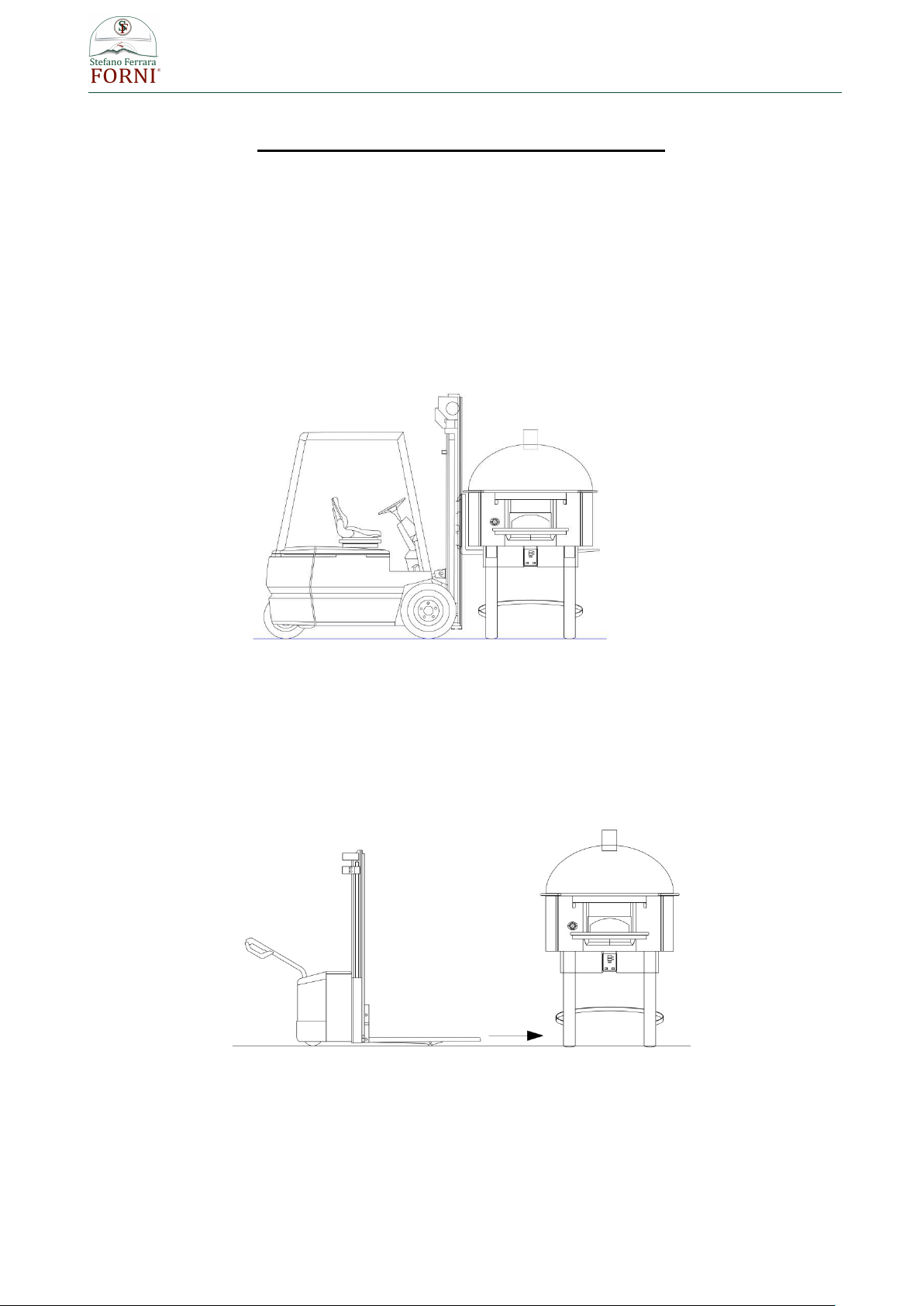
INSTRUCTIONS FOR LIFTING AND MOVING OVEN
FOR OVENS ALREADY INSTALLED ON THE SUPPORT STAND
1- USING A FORKLIFT
Determine if forklift capacity is sufficient to lift oven. (See pag. 11 for weights and sizes)
Prior to lifting, make sure the forks are long enough as whole diameter of the oven, if not fork extensions
should be used.
Keep forklift straight. Carefully place forks on a side of the oven through the stand legs and
position under the oven. Slowly lift and move the oven as needed
WARNING: MAKE SURE DON’T DAMAGE THE CABLES THAT COME OUT FROM THE
OVEN UNDER IT DURING INSERTING THE FORKS BETWEEN THE STAND LEGS.
2- USING A PALLET JACK
Determine if pallet jack capacity is sufficient to lift oven. (See pag. 11 for weights and sizes)
Prior to lifting, make sure pallet jack is long enough to reach both horizontal angles at lower end of steel tube
support legs. Place pallet jack on a side of the oven , place the forks between tube steel support legs under
the bottom circular tubes.
Carefully lift oven and move slowly.
www.stefanoferraraforni.it
8
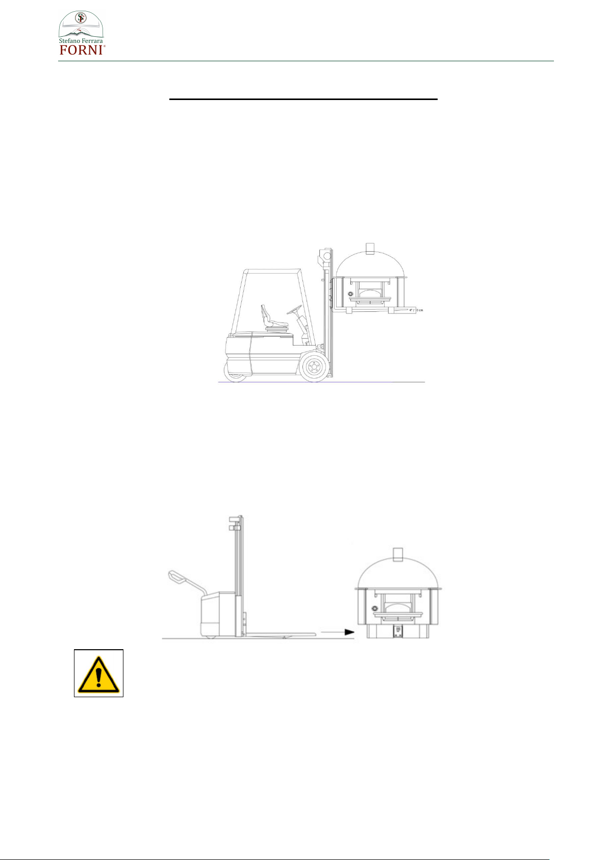
INSTRUCTIONS FOR LIFTING AND MOVING OVEN
FOR OVEN SHIPPED SEPARATELY FROM THE SUPPORT STAND
1- USING A FORKLIFT
Determine if forklift capacity is sufficient to lift oven. (See pag. 11 for weights and sizes)
Prior to lifting, make sure the forks are long enough as whole diameter of the oven, if not fork extensions
should be used.
Under the oven there are four little steel feet 4” (10 cm) high to permit placing of the forks.
Keep forklift straight. Carefully place forks on a side of the oven through the steel feet and position under the
oven. Slowly lift and move the oven as needed.
WARNING: MAKE SURE DON’T DAMAGE THE CABLES THAT COME OUT FROM THE OVEN UNDER IT
DURING INSERTING THE FORKS
2- USING A PALLET JACK
Determine if pallet jack capacity is sufficient to lift oven. (See pag. 11 for weights and sizes)
Prior to lifting, make sure the forks are long enough as whole diameter of the oven.
Place pallet jack between the steel feet and position under the oven.
Carefully lift oven and move slowly.
ONLY VERTICAL LIFTING IS ALLOWED DO NOT TURN UPSIDE DOWN THE
OVEN

www.stefanoferraraforni.it
9
PACKAGING REMOVING
On the bottom of the crate (front side and back side) there is the required space for insert the forks of the
forklift. (photo 1)
The crate is fixed to two metal brackets placed under the oven (photo 2)
photo 1 photo 2
Once removed the crate, in order to remove the brackets, lift the oven with a forklift and unscrew the bolts.
Note the removed bolts (17 mm. hexagonal head screw) will be the same to use for fixing the oven on the
support stand, so preserve them for the next use.
ASSEMBLY THE SUPPORT STAND
The support stand consist of:
N. 4 inox tubes (legs)
N. 7 inox curves plates of legs conjunction
N. 1 inox front paneling for housing of the control panel
All the pieces are labelled with numbers.
Assembly all the pieces respecting the order of the numbers and pairing the same numbers

www.stefanoferraraforni.it
10
PLACEMENT OF THE OVEN ON THE SUPPORT STAND
1. Lift the oven with a forklift until above the height of the metallic support stand (photo 3)
2. Let down carefully for inserting the steel feet placed under the oven into the legs of the support stand
(photo 4)
3. Once placed the oven on the support stand to screw the furnished screws (17 mm. hexagonal head
screw) in the existing holes on the back of each stand leg.(photo 5 – 6)
photo 3 photo 4
photo 5 photo 6
www.stefanoferraraforni.it
11
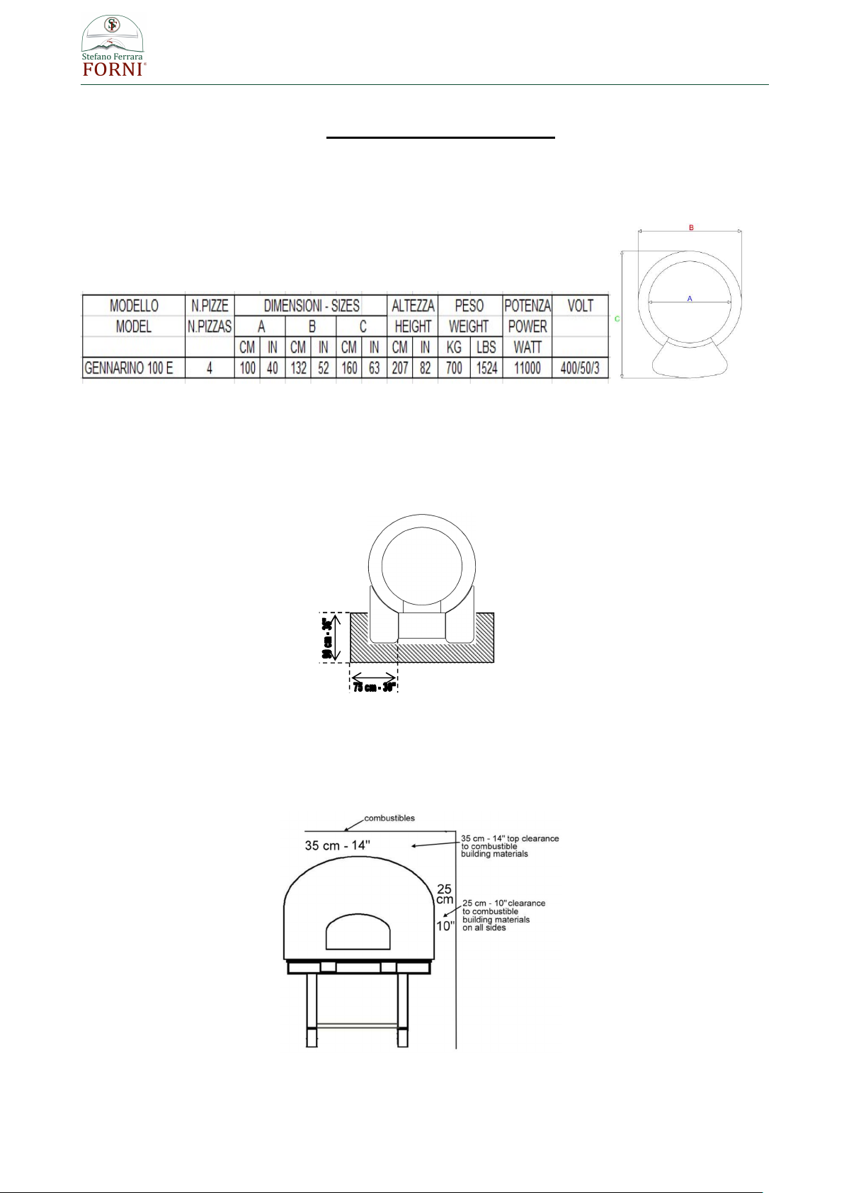
INSTALLATION PROCEDURES
1. Be sure to have a sufficient space in the desired location for the oven.
Minimum floor space required:
2. Place the oven on appropriate floor able to support the oven weight.
3. Any adjacent combustible floor which projects in front of the oven opening must be a minimum of 30
inches (75 cm) away from each side of the door opening and 36 inches (90 cm.) from the front of
the door opening.
4. It is essential to maintain clearance space between the oven components and any combustible
material, such as walls and ceilings.
The oven must have a minimum 10” (25 cm.) clearance to combustibles from all sides and 14" (35
cm) clearance to combustibles from the top.

www.stefanoferraraforni.it
12
5. Installation of components box and front panel for housing control unit display
A: Components box
B: Front panel of housing display
C: Automatic circuit breaker 32 A
D: Cable with industrial plug 32 A
a) Place the components box between the front legs of the stand (photo 1) and to ensure it to the
oven bottom by screwing the three screws on the back (photo 2)
photo 1 photo 2
b) Place the automatic circuit breaker on the oven side
The circuit breaker is fixed to a metallic stirrup (A photo 4) that will be to screw to the oven
bottom (B photo 4) and to the perimetral ring of the stand ( C photo 4)
photo 3 photo 4 photo 5

www.stefanoferraraforni.it
13
c) Front panel placement.
Insert the connector A ( photo 6 ) into its specific port on the back of the display (photo 7- 8).
photo 6
photo 7 photo 8
Place the front panel of housing display in front of the components box , screw the five
screws on the edges (1-2-3-4-5 photo 9 ) and the three screws on the bottom (A-B-C photo
9)
photo 9

www.stefanoferraraforni.it
14
d) Connect the plugs into the sockets on the back of the components box (photo 10) and fix it with
its locking lever.
Note : sockets and plugs are labelled (floor and top, see photo 10) make sure to connect each
plugs in the proper socket (Floor → Floor - Top → Top)
Do not reverse connections between plugs and sockets
photo 10
e) Fix the yellow-green grounding wire (photo 11) on the oven bottom (photo 12)
Correct position is labelled
Remove the existing screw, place the metallic end of the grounding wire and fix by screwing the
screw
photo 11 photo 12
6. Marble shelf placement
For greater safety, the oven is shipped without the marble shelf, you will find it into a separate
packaging. Fasten the marble on the existing iron support plate placed in front of the oven mouth
using some silicone and waiting until it will be completely dry before use them as support shelf.
www.stefanoferraraforni.it
15
ELECTRICAL CONNECTIONS
To put the oven into operation, the required connections to the local area network must be ensured.
The user is in charge of ensuring the required correct electrical connection characteristics, by making sure to
provide a proper grounding.
The oven works at 400V+T+N /50Hz
Total power is 11 Kw
Install a 32 A (3 phases + neutral + ground) electrical socket near the oven.
In case the use of the provided industrial plug isn’t compatible into your country, you can replace it using a
different model (rated current 32 A) suitable to the available socket existing into the installation place.
If the power cord isn’t enough long it can be replaced using a cord of the same sections and the same type
(five-pole cable three phases + neutral + ground, size 5 x 4 mm²
Keep electrical cables away from the hot parts of the oven.
WARNING !
Before making any the electrical connection, it is important to check that the machine is OFF.
Getting the circuit breaker provided with the oven turned OFF.
WARNING !
Make sure the power supply line has been isolated.
WARNING !
The connections to the plant's electricity network must be made by the Customer's qualified
personnel (Electrical Maintenance Engineer).
The purchaser is responsible for the conformity of the connection between machine and earthing system.
Before setting up the electrical connection, make sure that:
• the maintenance engineer is aware of the regulations in force in the country of installation;
• the frequency and power supply voltage values of the machine correspond to the power supply network
values;
• the section of the electrical cables used is adequate to the absorption;
• the electrical power supply line is adequate to support the maximum machine absorptions;
• the grounding of the circuit conforms with standards EN 60204-1 or however in compliance with the
standards of the installation place;
• the materials used in the grounding system have adequate strength or adequate mechanical protection.

www.stefanoferraraforni.it
16
ELECTRICAL MAINTENANCE
WARNING !
Before starting any maintenance operation disconnects electricity through the circuit breaker
In case of components/accessories replacement use only original spare parts.
Should the customer not use genuine spare parts or parts authorised in writing by the
Manufacturer, the latter shall be relieved of any liability as regards machine operation and
operators' safety.
Authorization and/or instructions must always be given in writing. It is forbidden to operate
the machine without written permission and the Manufacturer disclaims any and all
responsibility.
WARNING !
Maintenance and repair of the machine are only allowed by qualified technicians with
knowledge of equipments, necessary operations, related risks and correct procedure to work
safely.
ELECTRIC POWER CORD
In case of replacement, the correct type of cord to use is five-pole cable three phases + neutral + ground,
size 5 x 4 mm²
Leave the cord enough long to allow an easy maintenance.
A damaged cord should not be repaired but it must be replaced.
Power cord replacement must be made by specialized technicians.
BULB REPLACEMENT
Before to start any operation , disconnect elecricity and wait for the oven gets cool
Remove the glass protection of the bulb by unscrewing it, replace the bulb and reposition the glass
protection by screwing it into its place.

www.stefanoferraraforni.it
17
OVEN VENTING
The venting system of our wood burning ovens is to direct connection, exploiting the natural draught.
The oven employs an integral exhaust hood above the front opening. All flue gases exit the front opening and
drafts into the exhaust hood to be subsequently expelled through a flue pipe (150 mm / 6” O.D.) located at the
top of the oven.
As there isn’t any emission of exhaust gas but just smokes of cooking and heat the pipe need just to allow
venting of them so, if local regulations allow it, the oven could be placed under an exhaust hood avoiding
connection of the flue to a duct venting system (chimney),
WARNING !
Rules about ventilation change according the different jurisdiction of the country of
installation so submit your venting plans to local authorities about possible restrictions and
installation procedure accepted before proceeding with installations.
The purchaser is responsible of the conformity, correct installation and correct working of the
venting system.
www.stefanoferraraforni.it
18
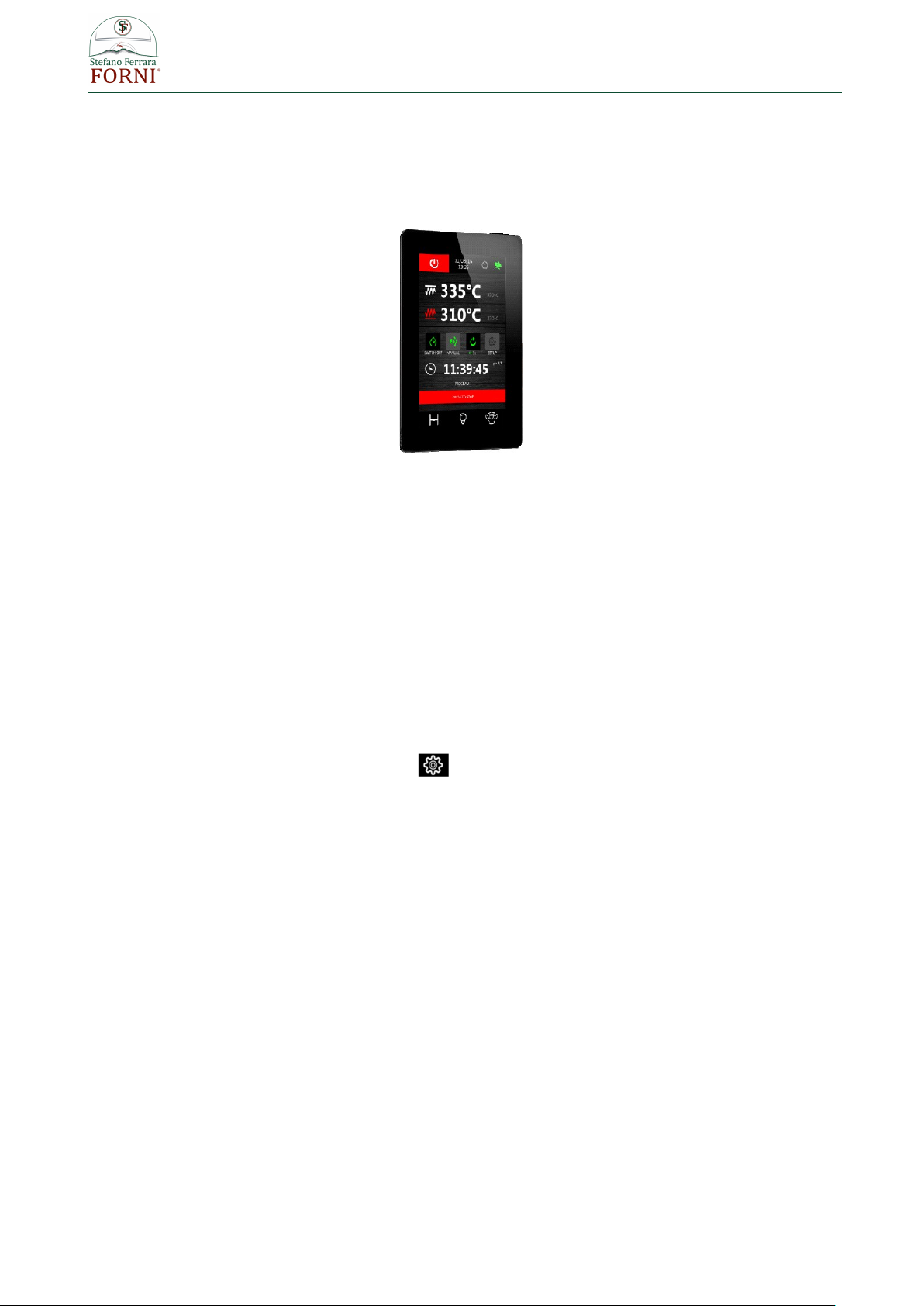
CONTROL UNIT
The oven is provided of a control unit for temperature management wich user interface consists of a
5 inch touch-screen graphic display of glass, 65K colours, 800 x 480 pixel resolution and IP65 protection for
easy cleaning.
USER INTERFACE
Initial information
The interface has the following operating modes:
"ON": the device is powered up and switched on; the loads can be switched on
"STAND-BY": the device is powered up but switched off by the software; the loads are switched off
"OFF": the device is not powered up; the loads are switched off.
FIRST USE
1. Connect electricity, a white splash screen will be displayed for few seconds.
2. Stand-by screen will be displayed.
3. Access to set up by pressing the button
4. Set correct data and time
5. Set the language.
6. Exit from set up function, stand by screen will be displayed again.
7. Press ON/OFF button for turn ON the oven
8. “ON Screen” will be displayed , the oven is ON and working
9. Act on this screen for setting the desired cooking temperature and the desired percentages of power
for the oven top and the oven floor.
10. To turn OFF the oven press ON/OFF button placed on left top of the “ON screen”
Please note : After a time of inactivity into operating on the dispaly it will pass to Screen Saver modality,
in this case to turn OFF the oven it’s sufficient to touch the display for getting again displayed “ON
screen” and acting on ON/OFF button

www.stefanoferraraforni.it
19
STAND-BY SCREEN
Stand-by screen displayed after the white splash screen will be like shown in the photo below
The oven gets turn ON by pressing ON/OFF button .
Setup button ,displayed on top right, allows to enter into date/time setting and parameters configuration.
CONFIGURATION
On the standby screen touch the key to move to the setup screen with the following functions menu. For
alarms and internal values, datas are only displayed.
· CLOCK
· ALARM LIST (displays alarms set)
· INTERNAL VALUES (displays real-time data)
· SERVICE
· LANGUAGES
To access the various procedures, touch the screen near the information/function required.
SETTING THE TIME, DATE AND DAY OF THE WEEK
1. Access the CLOCK menu by touching the corresponding line.
2. Touch repeatedly until the green rectangle shows the desired value.
To set a value use the or keys or the slide-bar.
To save, press the key .
To exit the procedure without making any changes, press the key .

www.stefanoferraraforni.it
20
LANGUAGES
1. Access the LANGUAGES menu by touching the corresponding line.
2. Touch the screen on the required language. The screen display the chosen language,
no need of pressing other keys for confirm.
ON SCREEN
The screen is like shown on the following photo
Possible settings are :
A : Chamber of cooking setpoint (desired working temperature). This value is reported on the right
side of the temperature measured into the chamber of cooking (B)
C : Top power
D : Floor power
E : Timer
Relay (C and D) :
Red → Relay ON
White → Relay OFF
Table of contents
Other FORNI Oven manuals


