FORNI GENNARINO User manual

www.stefanoferraraforni.it
GENNARINO
GAS OVEN
INSTALLATION AND OPERATING MANUAL
Gennarino Gas 80
Gennarino Gas 100
PLEASE READ ALL INSTRUCTIONS BEFORE INSTALLING AND USING
THE APPLIANCE
A MAJOR CAUSE OF OVEN-RELATED FIRE IS FAILURE TO MAINTAIN
REQUIRED CLEARANCES (AIR SPACES) TO COMBUSTIBLE
MATERIALS. IT IS OF UTMOST IMPORTANCE THAT THIS OVEN BE
INSTALLED ONLY IN ACCORDANCE WITH THESE INSTRUCTIONS.
SAVE THESE INSTRUCTIONS
Stefano Ferrara Forni S.R.L.
Forni a legna artigianali
Neapolitan handmade brick ovens
Via Fausto Coppi, 3/B
80010 Quarto, Napoli
Tel./Fax: +39 081 876 1664
e-mail: info@stefanoferraraforni.it
P.IVA 06771801211
C.C.I.A.A. 838246

2
www.stefanoferraraforni.it
Table of content
Page
- Introduction.............................................................................................................................................................. 3
- Installation operating and maintenance preface ...................................................................................................... 5
- Features .................................................................................................................................................................. 6
- Instruction for lifting and moving oven ..................................................................................................................... 7
- Packaging removing and placement oven on support stand ………………………………….... ................................ 9
- Installation procedures
•General information …………………………………………………………………………............................... 11
•Placement of the marble shelf …………………………………………………………………… ...................... 12
•Installation of the unit control housing ……………………………………………………………………........... 12
•Assembly of the burner............................................................................................................................... 12
•Burner installation....................................................................................................................................... 18
- Connections
•Electrical connection ………………………………………………………………………….............................. 16
•Gas connection …………………………………………………………………………...................................... 17
- Sample of LPG system ……………………………… ................................................................................................ 19
- Oven venting …………………………………………………………………………………………….............................. 20
- Oven care during first fires …………………………………………………………………………… .............................. 21
- Use of the oven with wood ...................................................................................................................................... 22
•Maintenance and cleaning ......................................................................................................................... 23
- Burner components.................................................................................................................................................. 24
- Control panel............................................................................................................................................................ 25
- Celsius/Fahreneit change ....................................................................................................................................... 26
- First ignition and adjustment.................................................................................................................................... 27
•First burner ignition..................................................................................................................................... 27
•Unlocking the burner ................................................................................................................................. 27
•Cooking temperature setting....................................................................................................................... 28
•Low flame gas adjustment.......................................................................................................................... 28
•Air adjustment............................................................................................................................................. 29
•Setting safety limit temperature ................................................................................................................. 31
•Burner operation with control panel............................................................................................................ 32
•On/Off function .......................................................................................................................................... 32
•High flame power adjustment .................................................................................................................... 32
•Switching the burner OFF through control panel........................................................................................ 33
•Error messages ......................................................................................................................................... 34
- Maintenance ............................................................................................................................................................ 35
•Routine maintenance ................................................................................................................................. 36
•Special maintenance ................................................................................................................................. 37
- Burner gas conversion............................................................................................................................................. 38
•Conversion on control panel ...................................................................................................................... 38
•Nozzles replacement.................................................................................................................................. 38
•Flame arrestor replacement ....................................................................................................................... 39
- Replacing components
•Sit control equipment replacement ............................................................................................................ 40
•Probe replacement .................................................................................................................................... 42
•Control Unit fuse replacement.................................................................................................................... 42
•Detection electrode replacement................................................................................................................ 42
- Error messages ....................................................................................................................................................... 43
- Troubleshooting....................................................................................................................................................... 44
•Control unit doesn’t switch on..................................................................................................................... 44
•Control unit turns on but the burner doesn’t start ...................................................................................... 44
•Control unit turns on, the spark strikes, low flame doesn’t turn ON and the burner blocks ........................ 44
•The control unit turns ON, low flame turns ON but the burner blocks and flame turns OFF ...................... 45
•Low flame turns ON but after 15-20 seconds high flame does not turn ON................................................ 45
•Probe fault led turns ON............................................................................................................................. 45
•Red display with “- - -”................................................................................................................................. 46
•Green display: Set T° does not increase ................................................................................................... 46
•Slower heating than the normal parameters .............................................................................................. 46
•Soot under the dome ................................................................................................................................. 47
•Red display (T° inside the oven exceeds the green display (set T°) with high flame led OFF.................... 47
- Control unit diagram................................................................................................................................................. 48
- Connections diagram .............................................................................................................................................. 48

3
www.stefanoferraraforni.it
INTRODUCTION
This manual has been made so that the user of the oven can work in complete safety.
THE USER HAS OBLIGATION TO READ CAREFULLY AND TO OBSERVE CAREFULLY THE
INSTRUCTIONS OF THE MANUAL.
Failure to comply with the instructions contained in this manual, means to operate in the conditions of use
not foreseen by the manufacturer.
THE MANUFACTURER IS NOT LIABLE FOR ANY DAMAGES CAUSED BY THINGS OR PERSONS,
DUE TO THE FAILURE TO OBSERVE THE INSTRUCTIONS AND THE RECOMMENDATIONS IN THIS
MANUAL.
The manual must be kept in good condition and must always be available for quick reference in case of
need.
THE MANUAL IS OF OWNERSHIP OF THE MANUFACTURER AND CANNOT BE REPRODUCED EVEN
PARTIALLY, AS WELL AS IT CANNOT BE DIFFUSED OR USED FOR ADVERTISING PURPOSE OR
SHARED WITH THIRD PARTIES.
ANY TRANSGRESSION WILL HAVE CIVIL AND PENAL SANCTIONS AS A CONSEQUENCE.
EXPLANATION OF SYMBOLS AND WARNINGS
SYMBOL DESCRIPTION
Symbol used to identify information of particular importance within the manual. The
information also concerns the safety of the personnel involved in the use of the
machine.
Symbol used to indicate passages of technical importance in the instructions and
warnings or procedures related to operator safety.
Symbol used to indicate warnings or procedures related to electricity.
NOTE ON THE PRODUCT
The aim of the manufacturing company is to make ovens that meet the current technical state. So we always
take care of our products even after delivery.
For any problems or inconveniences contact the service center:
Email: info@stefanoferraraforni.it - tel. +39 081 876 16 64

4
www.stefanoferraraforni.it
INTRODUCTION ABOUT INSTRUCTIONS OF WORKING
These instructions have the task of allowing and facilitating the safe and appropriate use of the OVEN and of
exploiting the regulatory use possibilities provided.
Their observance helps to avoid dangers, repair costs, to reduce off-duty times and to increase the lifespan
of the device.
Operating instructions are to be followed also taking in consideration the regulations on accident prevention
and environmental protection valid in the country of installation
BUYER'S OBLIGATIONS
The buyer is obliged to:
• Observe the national regulations concerning workplace safety;
• Observe the instructions contained in the manual.

5
www.stefanoferraraforni.it
INSTALLATION OPERATING AND MAINTENANCE PREFACE
WARNING !
READ THIS ENTIRE MANUAL BEFORE YOU INSTALL THE OVEN. FAILURE TO
FOLLOW INSTRUCTIONS MAY RESULT IN PROPERTY DAMAGE, BODILY INJURY, OR
EVEN DEATH.
•When this oven is not properly installed, a fire may result. To reduce the risk of fire, follow the
installation instructions
•Contact your local building or fire officials for clarification on any restrictions on installation of this
oven in your area, or need for inspection of the oven installation.
•DO NOT close the oven door while a fire is in the oven.
•Place the door over the oven opening after cooking is completed at the end of the work day.
•Hot while in operation. Keep children, clothing and furniture away. Contact may cause skin burns.
•Do not burn garbage or flammable fluids.
•Smokes of the burning must be expelled through a flue system conform to the local rules.
•Do not connect the oven to a chimney flue serving another appliance.
•Keep children and pets away from hot oven.
•DO NOT USE products not specified for use with this oven.
•DO NOT USE liquid fuel (firelighter fluid, gasoline, lantern oil, kerosene or similar liquids) to start or
maintain a fire.
•DO NOT use water to dampen or extinguish fire in the oven.
•Keep a proper extinguisher (class A) close to the oven at all times.
•Instruct all personnel about location and use of the fire extinguisher and proper fire emergency
procedures.
•DO NOT pack required air spaces with insulation or other materials.
•DO NOT expose the oven to the weather, if the oven is installed outdoors to shelter it under a
canopy.
•The oven is meant only for cooking pizza and/or bread it is not recommended for cooking other food
or food in pan ,chafe of metal pans can get the floor soon damaged and grease spatter from
roasting can be absorbed from the floor that lose its correct properties of cooking.
•DO NOT pack required air spaces with insulation or other materials.
•In case of use of the oven with wood use only well dried wood.
•In case of use of the oven with wood, use a metal shovel to remove the ashes and place them in a
metal bin with a tightly fitting lid. The container should be stored on a non-combustible surface, away
from all combustible materials. Ensure ashes are completely cold before disposing of them
appropriately.
•DO NOT expose the oven to the weather, if the oven is installed outdoors to shelter it under a
canopy.
•The oven is meant only for cooking pizza and/or bread it is not recommended for cooking other food
or food in pan ,chafe of metal pans can get the floor soon damaged and grease spatter from
roasting can be absorbed from the floor that lose its correct properties of cooking
SAVE THESE INSTRUCTIONS

6
www.stefanoferraraforni.it
FEATURES:
Cooking chamber made of refractory bricks
Fully insulated
Support frame and front enclosure of stainless steel
Marble shelf
Inox door
Mouth sizes mm. 400 wide x mm. 175 heigh (16” x 7”)
External covering of ceramic mosaic tiles
Alimentation: gas
Electronic burner with one modulating flame max thermal capacity kW.24 – kcal/h 20640
Burner working temperature : 0°C to 500°C (32°F – 932°F)
Electronic unit control for temperature management
Gas consumption at max. temperature:
- Natural gas: 2,54 Nmc/h
- LPG : 0,86 Nmc/h
Flue output: Ø 150 mm.
Max heat output: 20640 kcal – 24 kW
Smokes temperature output: 190°C
Electrical supply: 220V – 50/60Hz one phase
Electrical absorption:100 Watt
Extract air flow: 650 mc/h (at starting)
500 mc/h (at fully operating)
Venting: Natural draft
Gas connection: 1/2”
Gas pressure:
- Methane : from 15 mbar - to 25 mbar
- LPG : from 25 mbar - to 50 mbar
It’s required a direct connection of the tube that serves the oven from gas meter to the oven no other
equipment must be installed on the same line between the meter and the oven.
For the gas line use the follows pipes size:
- Distance from the gas meter to the oven until 10 meters (32 ft) use:
For LPG ½“ pipe
For Natural gas ¾” pipe
Distance from the gas meter to the oven over 10 meters (32 ft) use 1” pipe (independently to the gas in use)

7
www.stefanoferraraforni.it
INSTRUCTIONS FOR LIFTING AND MOVING OVEN
FOR OVENS ALREADY INSTALLED ON THE SUPPORT STAND
1- USING A FORKLIFT
Determine if forklift capacity is sufficient to lift oven. (See pag. 11 for weights and sizes)
Prior to lifting, make sure the forks are long enough as whole diameter of the oven, if not fork extensions
should be used.
Keep forklift straight. Carefully place forks on a side of the oven through the stand legs and
position under the oven. Slowly lift and move the oven as needed
WARNING: MAKE SURE DON’T DAMAGE THE BURNER DURING INSERTING THE
FORKS BETWEEN THE STAND LEGS.
2- USING A PALLET JACK
Determine if pallet jack capacity is sufficient to lift oven. (See pag. 11 for weights and sizes)
Prior to lifting, make sure pallet jack is long enough to reach both horizontal angles at lower end of steel tube
support legs. Place pallet jack on a side of the oven , place the forks between tube steel support legs under
the bottom circular tubes.
Carefully lift oven and move slowly.

8
www.stefanoferraraforni.it
INSTRUCTIONS FOR LIFTING AND MOVING OVEN
FOR OVEN SEPARATED FROM THE SUPPORT STAND
1- USING A FORKLIFT
Determine if forklift capacity is sufficient to lift oven. (See pag. 11 for weights and sizes)
Prior to lifting, make sure the forks are long enough as whole diameter of the oven, if not fork extensions
should be used.
Under the oven there are four little steel feet 4” (10 cm) high to permit placing of the forks.
Keep forklift straight. Carefully place forks on a side of the oven through the steel feet and position under the
oven. Slowly lift and move the oven as needed.
2- USING A PALLET JACK
Determine if pallet jack capacity is sufficient to lift oven. (See pag.11 for weights and sizes)
Prior to lifting, make sure the forks are long enough as whole diameter of the oven.
Place pallet jack between the steel feet and position under the oven.
Carefully lift oven and move slowly.
WARNING : ONLY VERTICAL LIFTING IS ALLOWED DO NOT TURN UPSIDE
DOWN THE OVEN

9
www.stefanoferraraforni.it
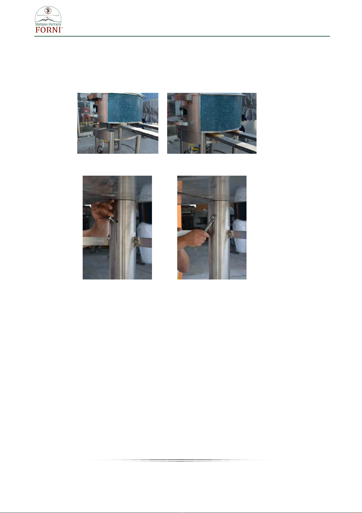
PACKAGING REMOVING AND PLACEMENT OF THE OVEN ON SUPPORT STAND
On the bottom of the crate (front side and back side) there is the required space for insert the forks of the
forklift. (photo 1)
The crate is fixed to two metal brackets placed under the oven (photo 2)
photo 1 photo 2
Once removed the crate, in order to remove the brackets, lift the oven with a forklift and unscrew the bolts.
Note the removed bolts (17 mm.- 0.67 in hexagonal head screw) will be the same to use for fixing the oven
on the support stand, so preserve them for the next use.
ASSEMBLY THE SUPPORT STAND
The support stand consist of:
N. 4 inox tubes (legs)
N. 7 inox curves plates of legs conjunction
N. 1 inox front paneling for housing of the control panel
All the pieces are labelled with numbers.
Assembly all the pieces respecting the order of the numbers and pairing the same numbers
10
www.stefanoferraraforni.it
Lift the oven with a forklift until above the height of the metallic support stand (photo 3)
Let down carefully for inserting the steel feet placed under the oven into the legs of the support stand (photo
4)
Once placed the oven on the support stand to screw the furnished screws (17 mm. hexagonal head screw)
in the existing holes on the back of each stand leg.(photo 5 – 6)
photo 3 photo 4
photo 5 photo 6

11
www.stefanoferraraforni.it
INSTALLATION PROCEDURES
1. Be sure to have a sufficient space in the desired location for the oven.
Minimum floor space required:
2. Place the oven on appropriate floor able to support the oven weight.
3. Any adjacent combustible floor which projects in front of the oven opening must be a minimum of 30
inches (75 cm) away from each side of the door opening and 36 inches (90 cm.) from the front of
the door opening.
4. It is essential to maintain clearance space between the oven components and any combustible
material, such as walls and ceilings.
The oven must have a minimum 10” (25,5 cm.) clearance to combustibles from all sides and 14"
(35,5 cm) clearance to combustibles from the top.
Warning : Don’t place any type type of insulation in the required clearance spaces surrounding the
oven
12
www.stefanoferraraforni.it
5. Placement of the marble shelf
For greater safety, the oven is shipped without the marble shelf, you will find it into a separate
packaging. Fasten the marble on the existing iron support plate placed in front of the oven mouth
using some silicone and waiting until it will be completely dry before use them as support shelf.
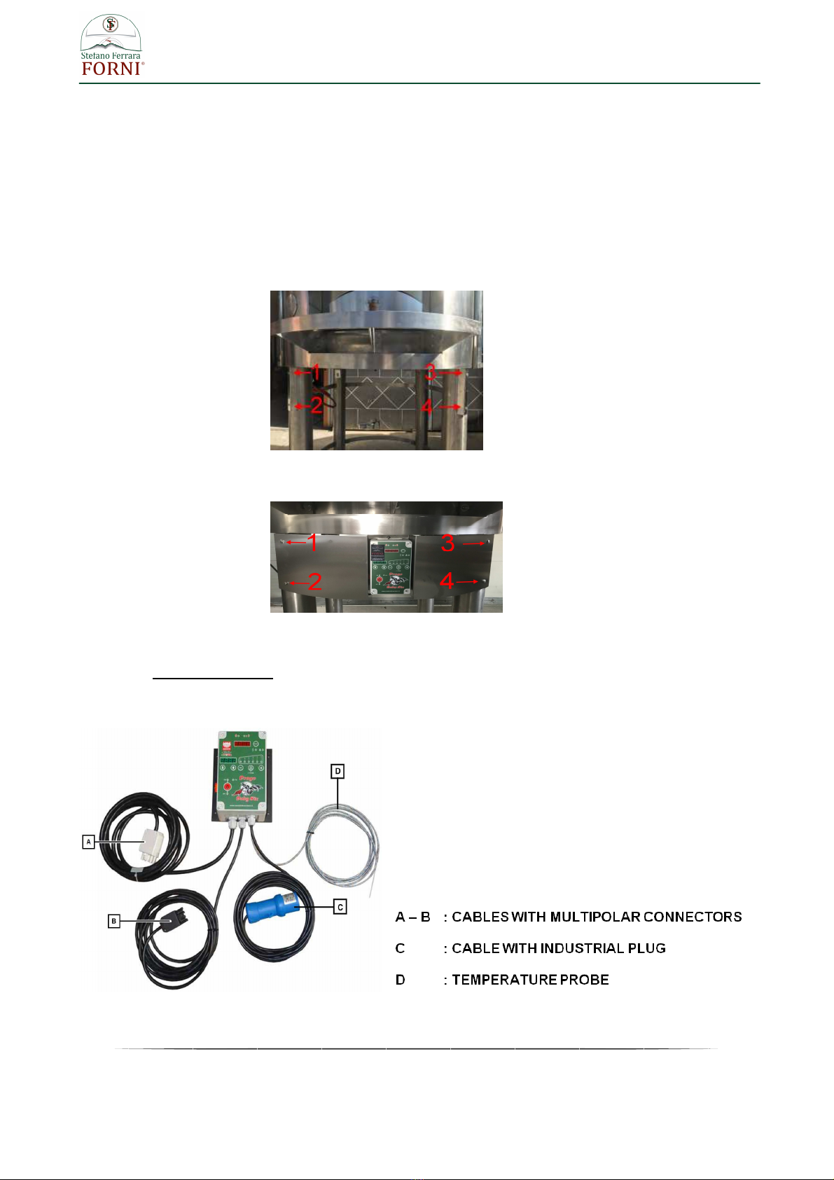
6. Installation of the unit control housing.
a) Introduce the unit control housing between the front legs of the support stand letting the holes of
the frontal inox panel coincide with the ones existing on the anterior stand legs (points 1 – 2 – 3
– 4 photo 1).
photo 1
b) Once the housing is correctly placed fasten the four screws at the corners of the frontal inox
panel (photo 2) .
photo 2
7. Assembly of the burner
7.1 Temperature probe
The electronic unit control is installed on the front paneling of the housing containing cables and probe
photo 3
13
www.stefanoferraraforni.it
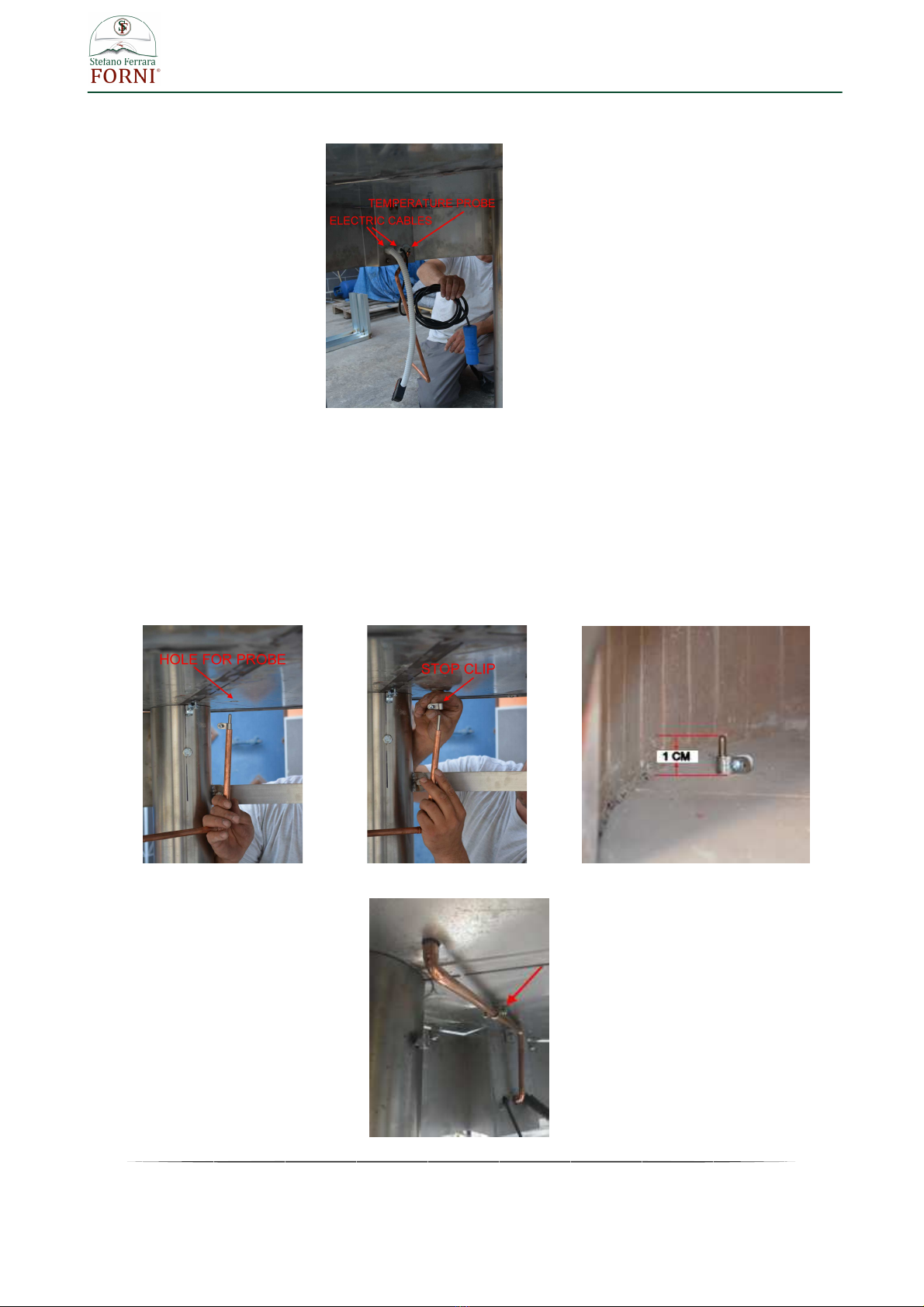
The temperature probe is inserted in a copper pipe placed on the back of the housing . (photo 4)
photo 4
Insert the probe into the hole on the oven bottom (photo 5) until getting it in the cooking room to a height of
around 1 cm (0.40 in). The probe must protrude not more than 1 cm from the oven floor.
Hole for probe is placed on the same side of the hole for the burner. Before to insert the the probe remove
the stop clip (photo 6).
Once placed the probe into the oven, place the stop clip for keeping it at the correct position (photo 7) , get
inserted the copper pipe of probe protection in the same hole and fix it at the oven bottom with the pipe clip
(photo 8)
Pipe clip is contained into the burner box, screw the clip at the oven bottom (hole for the screw is labelled
"pipe clip"), get fastened the copper pipe by screwing the two lateral screws of the clip
photo 5 photo 6 photo 7
photo 8

14
www.stefanoferraraforni.it
7.2 Burner
Before installing the burner , check the correct position of the electrode of the burner by following the below
procedure :
photo 1 photo 2
Check that the burner electrode discharge the spark onto the edge of the “A” circumference of one of
the holes of the external series of the flame breaker. (photo 1)
The tip of electrode “B” must be at a distance of 3 mm -0.12 in from the surface of flame arrestor “A”.
(photo 2)
Insert the burner in the hole under the oven making sure the holes of the fixing flange (“A” photo 3)
coincide with the three existing pivots on the sides of the burner hole (“B” photo 3).
To screw the nuts (hexagonal nut 13 mm – “C” photo 3 ) until to fix strongly the burner
photo 3
Connect the burner to the control panel inserting the connectors A and B (photo 3 page 12) into the sockets
A and B placed on the bottom of support plate of the control equipment (photo 4 below)
photo 4

15
www.stefanoferraraforni.it
Connect the gas to the gas inlet Ø1/2” of the burner (point C – photo 4 previous page) and the blue plug ( C
photo 3 page 12) to a CEI 220V. 16A. 50HZ. electrical socket.
When requested a transformer is provided for allowing the working of the burner with different voltage than
220 V . In this case the electrical cable isn’t provided of any blue plug (C photo 3 page 12) and it will be
need connect to the cable an appropriate plug can be inserted in the existing socket on the place of installing
oven.
Take care to not exchange phase - neutral connection
Electrical lines must be placed sufficiently spaced from the hot parts of the oven
INSTALLATION ROOM VENTILATION:
The room where the oven is installed must be equipped with a suitable air intake that cannot be closed or
tampered with ( windows and doors cannot be considered suitable air intakes).
Direct air intake:
- rectangular opening: 200 mm x 200 mm (8 in x 8 in)
- round opening: Ø 250 mm (10 in)
If there is an extractor hood in the room, you need to increase the air intake by considering the air amount
extracted from the hood (according to its label) and considering that the burner requires 30-40 m ³ of air per
hour during operation (17.66- 23.50
ft
3
/min)
. If the air intake is too little, pressure variations are generated
and the burner may not work properly.
DRAUGHTS
The room must not have draughts that can cause malfunctions, such as an irregular flame or burner switch-
off: in the presence of draughts, that cannot be eliminated ( e.g. oven installed in a room with 2 windows
opposite each other) the base of the oven must be closed on three sides (right, left and back and the front
must remain open) so that the burner is protected from draughts without being isolated from the room where
it draws the air.
If the oven rests on a closed base, you need to create a minimum opening of 500 mm x 500 mm (20 in x 20
in) under the oven opening to ensure the correct amount of air reaches the burner.

16
www.stefanoferraraforni.it
CONNECTIONS
To put the machine into operation, the necessary connections to the local area network must be ensured:
• electrical connection;
• connection to the gas network (natural gas, LPG, town gas).
The user is in charge of ensuring the connection characteristics required.
ELECTRICAL CONNECTION
The burner works at 230 Volt, 50-60 Hertz. If this is not the standard electricity in your country, a specific
transformer is required for your voltage (available on request).
The power supply line must preferably be protected by a 6A automatic circuit breaker switch inside the
electrical panel or in other suitable position.
Fit a blue 220V 16A IEC industrial socket in a position near the oven, ideally under it. The total electrical
absorption of the burner is 100 Watt.
It is essential to respect the phase/neutral connection: one of the most common problems is that the burner
blocks because this connection is reversed.
In case the use of the industrial plug of which the burner is provided isn’t compatible into your country, you
can replace it using a different model (rated current 16 A) suitable to the available socket into the installation
place.
WARNING !
Before making the electrical connection, it is important to check that the machine is off. Then
set the main switch to “OFF”.
WARNING !
Make sure the power supply line has been isolated.
WARNING !
The connections to the plant's electricity network must be made by the Customer's qualified
personnel (Electrical Maintenance Engineer).
The purchaser is responsible for the conformity of the connection between machine and grounding system.
Before setting up the electrical connection, make sure that:
• the maintenance engineer is aware of the regulations in force in the country of installation;
• the frequency and power supply voltage values of the machine correspond to the power supply network
values;
• the section of the electrical cables used is adequate to the absorption;
• the electrical power supply line is adequate to support the maximum machine absorptions;
• the grounding of the circuit conforms with standards EN 60204-1
or however in compliance with the
standards of the installation place;
• the materials used in the grounding system have adequate strength or adequate mechanical protection.
WARNING !
It is the customer's responsibility to protect the power supply line of the machine.
IMPORTANT !
Comply with the PHASE/NEUTRAL connection; reversing the connection causes the burner to
not switch on.

17
www.stefanoferraraforni.it
GAS CONNECTION
The machine uses gas for its own operation, and it is designed and built for the use of specific gases; please
refer to the information found on the CE plate affixed to the burner in order to identify the type of gas to be
used.
Connect the gas system using a 1/2” hose.
WARNING !
Do not use the burner with gases other than the ones indicated on the CE plate. The factory
declines any and all responsibility with regards to gases other than the ones indicated on the
CE plate of the burner. faults resulting from the use of
WARNING !
The gas supply system must be properly designed and built, according to the regulations in
force in the country of installation.
WARNING ! Upstream the burner connection point, install a tap having suitable characteristics.
The Customer is responsible for installing the tap.
WARNING !
Connections to the gas network should be carried out by the Customer’s qualified personnel.
NATURAL GAS CONNECTION
1) Connect the gas supply to the 1/2” male fitting “A” on the burner.
2) Make sure the pressure is included between 17 and 23 mbar. For countries with 10 mbar
standard, make sure the pressure is between 9 and 13 mbar.
WARNING !
Periodically check that the operating pressure is correct.
In case of insufficient pressure, the burner may experience malfunctions or switch off.

18
www.stefanoferraraforni.it
Below the procedure for checking the supply pressure with the burner on:
1) Identify the connection point of the pressure gauge in the bottom part of the burner.
2) Unscrew the screw cap “A” located inside the connection point of the pressure gauge.
3) Connect a pressure gauge (not supplied as standard equipment) to the connection point.
4) Measure the supply pressure with the burner on.
5) Disconnect the pressure gauge from the connection point.
6) Screw the screw cap “A” located inside the connection point of the pressure gauge.
MINIMUM REQUIREMENTS OF THE NATURAL GAS COUNTER
- 3 m³ for domestic use,
- 6 m³ for commercial use.
The gas system must be compliant with the legal standards of the installation place , designed and built
(according to local regulations on the safety of the fuel gas systems) by a skilled and qualified technician.
It’s recommended, once the burner is installed, to check the gas system seal.
It’s required a direct connection of the tube at oven service from gas meter to the oven no other equipment
must be installed on the same line between the meter and the oven to avoid pressure drop could
compromise the good working of the burner
For the gas line use the follows pipes size:
- Distance from the gas meter to the oven until 10 meters (32 ft) use:
For LPG ½” pipe
For Natural gas ¾” pipe
- Distance from the gas meter to the oven over 10 meters (32 ft) use 1” pipe (independently to
the gas in use)
LPG CONNECTION:
LPG supply can be with:
• a 500-litre tank, equipped with a first stage pressure reducer and pressure regulator (minimum 12 kg/h);
• cylinders, with a capacity of at least 50 kg, equipped with a manifold with a 30 mm diameter with the
following equipment: safety valve, pressure gauge, first stage reducer APZ 30-60 Kg/h calibrated to 1.5 bar,
pressure regulator 12 kg/h calibrated to 30 mbar (visible from the special pressure gauge) and 1/2” piping.

19
www.stefanoferraraforni.it
SAMPLE OF LPG SYSTEM
1. Ø30 manifold with pressure gauge and safety valve.
2. Flexible hoses to the cylinders.
3. APZ 30-60 Kg reducer calibrated at 1.5 bar.
4. 12 kg pressure regulator adjusted at 30 mbar.
5. Outfeed pressure gauge.
6. ½ flexible fitting hose to burner.
7. Burner.
WARNING !
For component No.2 (flexible hose to the cylinders), it can happen that the connections provided
by us are not compatible with the cylinders that the customer is able to find locally; the customer is
responsible for the cylinder connection.

20
www.stefanoferraraforni.it
OVEN VENTING
The venting system of our wood burning ovens is to direct connection, exploiting the natural draught.
The oven employs an integral exhaust hood above the front opening. All flue gases exit the front opening and
drafts into the exhaust hood to be subsequently expelled through a flue pipe (150 mm / 6 in O.D.) located at the
top of the oven.
The flue pipe is intended to be connected to a natural draft chimney system complying with the regulations on
the matter existing in the installation country or complying with NFPA96 (for USA and Canada)
For the flue system we recommend to use a building heating appliance chimney grease duct assembly , (UL
listed for USA and Canada or complying with the local regulations for other countries).
Stainless steel pipes single or twin-walled 150 mm/6 “ in diameter (meant as internal diameter in case of twin
walled pipes) to connect from the chimney connector existing on the top end of the oven up to the desired
place where the smokes will go out.
Induct the elements according to the toward of the smokes. The toward of the smokes is understood from
the “ masculine” to the “female” part.
Sew together the elements having care of not damage the seal inserted in the female part. It is advisable to
lubricate the masculine part with a light coat of fat, spray or liquid soap.
To mount and to shut the security wrappers for every junction.
WARNING !
The above information are just some suggestions , for building the flue system is of utmost
importance contact a specialized company and submit your venting plans to local authorities
before proceeding with installations.
The purchaser is responsible of the conformity, correct installation and correct working of the flue
system.
This manual suits for next models
2
Table of contents
Other FORNI Oven manuals


