FORST PT6 User manual

Redwood Global Ltd,
Unit 86, Livingstone Road, Walworth Business Park, Andover,
Hampshire. SP10 5NS. United Kingdom
PT6
Woodchipper
USER MANUAL
ENGLISH
3/12/2015 Revision 0

P a g e | 1
Table of Contents
Introduction...........................................................................................................................3
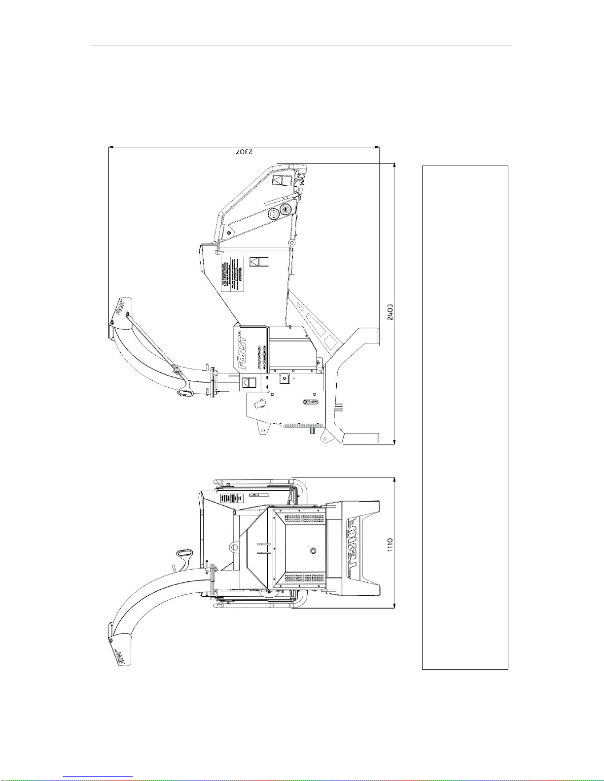
Purpose of machine..............................................................................................................4
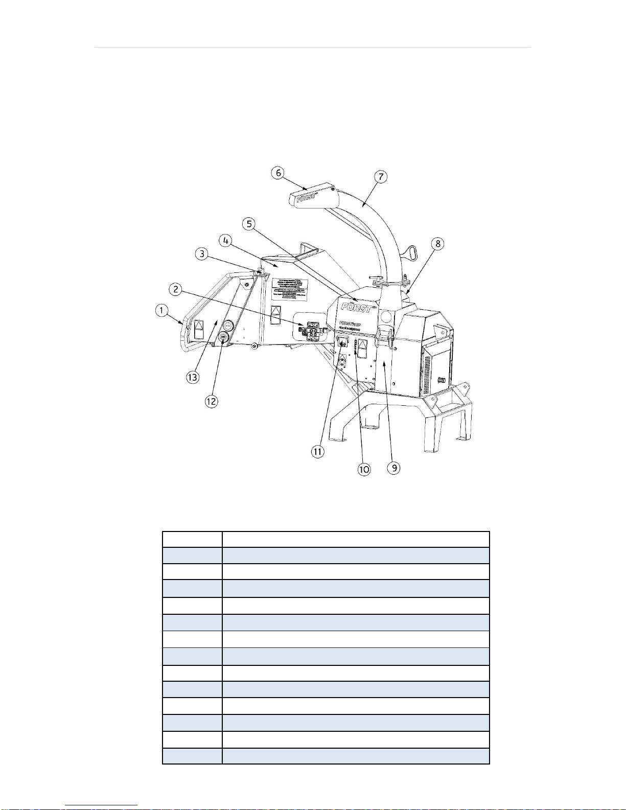
Exterior component identification ..........................................................................................5
Safe working .....................................................................................................................................6
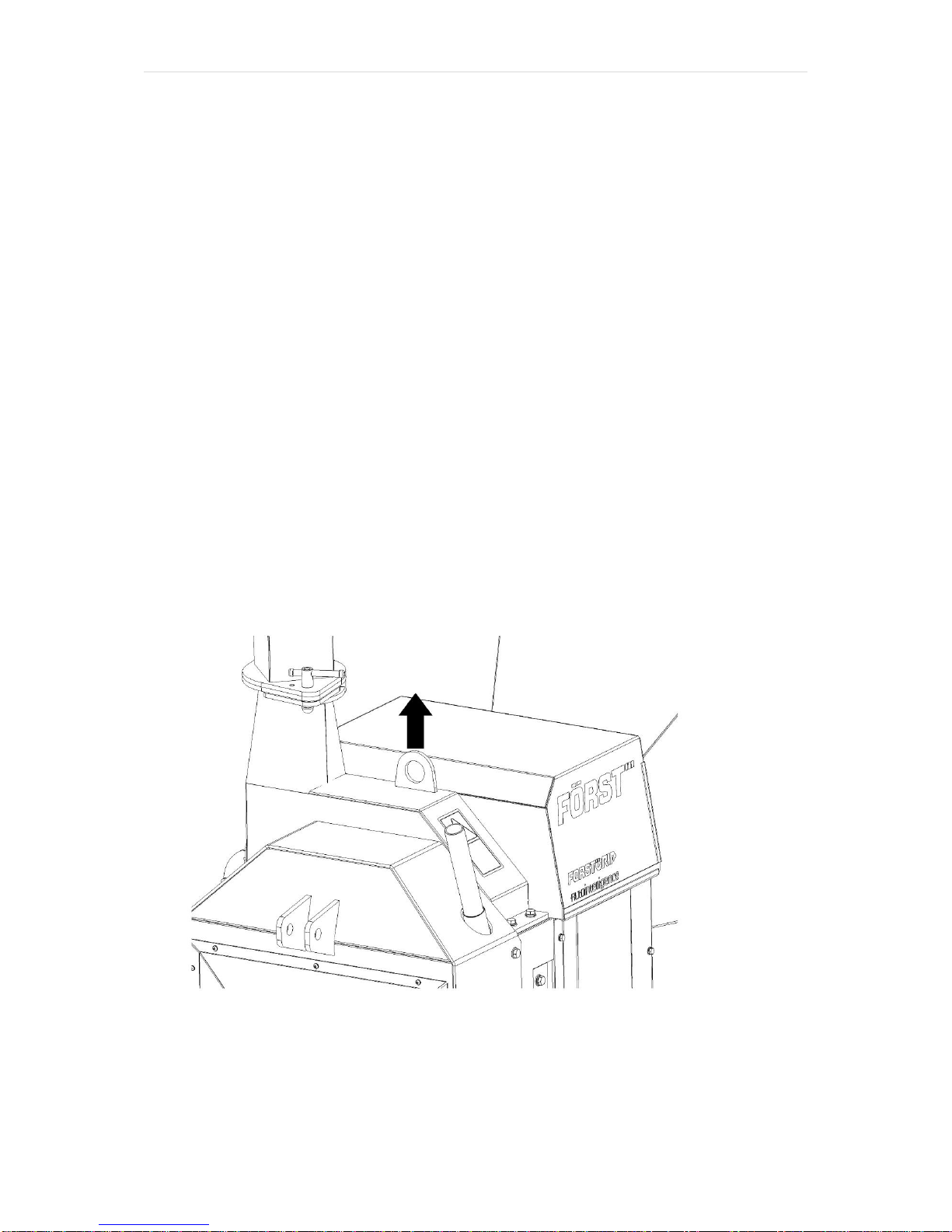
Machine lifting...................................................................................................................................7
DOs and DON’Ts .............................................................................................................................8
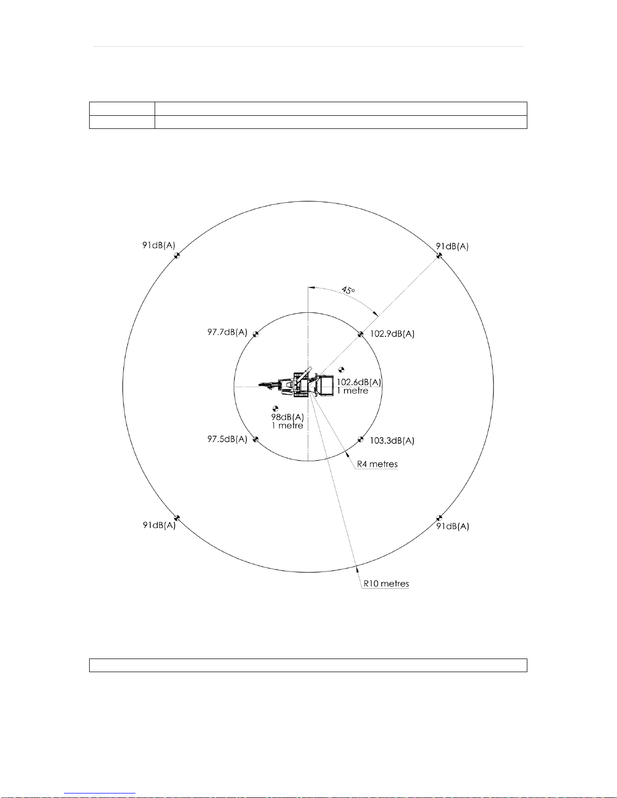
Noise test information ...........................................................................................................9
Machine operation ..............................................................................................................10
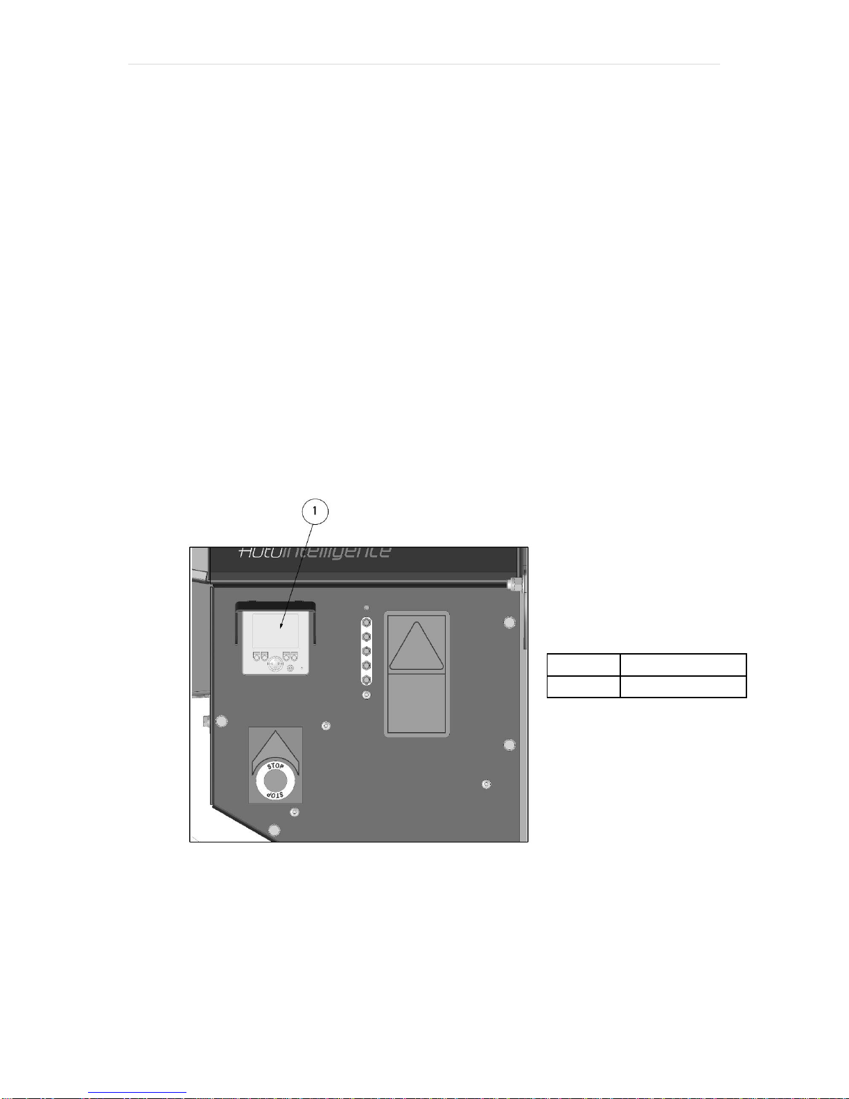
Machine control panel, start/stop & operating settings ............................................................11
Feed speed adjustment.................................................................................................................13
Feed jam & blockages.........................................................................................................13
Attaching to the Tractor.................................................................................................................15
Transportation.....................................................................................................................15
Stopping the Chipper.....................................................................................................................15
Disconnecting from the Tractor...........................................................................................16
Routine maintenance..........................................................................................................16
Fastener tightening torques..........................................................................................................17
Blade sharpening ...........................................................................................................................19
Hydraulic oil filter............................................................................................................................20
Drive belt tension............................................................................................................................22
Hopper tray touch sensor..........................................................................................................23
Chipping chamber assembly........................................................................................................24
Chipping chamber assembly - Bottom feed..............................................................................24
Chipping chamber assembly - Bottom feed & anvil.................................................................26
Chipping chamber assembly - Drive..........................................................................................27
Chipping chamber assembly - Flywheel drive..........................................................................28
Chipping chamber assembly - Bottom feed roller cover.........................................................29
Chute assembly............................................................................................................................30
Top feed roller assembly...............................................................................................................31
Flywheel assembly.........................................................................................................................32
Flywheel belt tensioner assembly...........................................................................................33
Hydraulic pump assembly.........................................................................................................34
PTO Assembly Parts………………………………………………………………..………………35
Hydraulics circuit diagram...................................................................................................36
Electrical circuit diagram –PTO touch sensor hopper.........................................................37

P a g e | 2
Decals.................................................................................................................................38
Manufacturer’s Statutory Plate ............................................................................................39
Warranty.............................................................................................................................40
CE Certificate......................................................................................................................41

P a g e | 3
Introduction
Thank you for becoming the owner of this Redwood Global Ltd, Forst PT6
woodchipping machine. By observing the contents of this manual, we hope the
machine gives safe and productive service. This user manual is intended for the
owner/operator to safely and effectively operate this machine and carry out routine
maintenance between services. This is not a comprehensive service manual. See
Service Schedule for routine maintenance and when to take the machine to a service
specialist. For engine maintenance, please refer to the engine manual supplied with
this machine.
This machine has been through a pre-delivery inspection before leaving the factory
and is ready to use.
Before use and as a minimum, the safety and machine operation
sections covered on pages 4 to 13 must be read and understood.
Failure to do so could result in serious injury or loss of life to the
operator and others nearby.Also, damage to property and this machine may
occur. Please observe and obey all warning signs (decals) located on the machine.
Their meaning is covered in this manual under decals.
All personnel working with this machine must be adequately trained in its use and
most importantly, follow the advice on safe working practices.
Redwood Global Ltd endeavour to continuously develop and improve its products.
They reserve the right to make changes at any time, without notice or incurring any
obligation.
Continuous improvement will affect machine design and production so there may be
minor discrepancies between the actual product and this manual.
This manual must remain with the machine for reference by operators and includes
hiring or if the machine is resold.

P a g e | 4
Purpose of machine
The Forst PT6 is designed to reduce wood material up to 150mm diameter to
woodchip. This machine is capable of processing up to 5 tonnes of wood per hour.
Power source
Tractor PTO
Roller feed
Twin series hydraulic motors
PTO speed
540rpm
Maximum material diameter
150mm
Required engine hp
25-50hp
Hydraulic oil capacity
20 litres
Overall weight
630kg
Material processing capacity
5 Tonnes/Hr
3 Point Mounting
CAT. 1 / 2

P a g e | 5
Exterior component identification
Figure 1
ITEM NO.
PART DESCRIPTION
1
Trip Bar
2
Control Valve Feed Speed Adjustment
3
Hopper Tray latch
4
Hopper
5
Chipping Chamber Cover
6
Chute Hood
7
Chute Chamber Cover
8
Machine Lifting Eye
9
Chipping Chamber
10
Grease Point
11
Control Panel
12
Feed Start/Stop Touch Sensors
13
Hopper Tray

P a g e | 6
Safety
Safe working
Before using this machine, make sure that you are trained and fluent in its operation.
Know the location of and how to use all the safety features. Know how to control the
feed and stop the machine in an emergency. Be familiar with the hazards and safe
working practices to prevent injury and damage to property and machine. Also be
aware of the legal restrictions for personnel and towing with vehicles.
1. The minimum age for service personnel is 18 years. Personnel aged 16 can
use the machine for training under supervision by a suitably trained person of
18 years or over.
2. Operators and personnel working with this machine must not be under the
influence of alcohol, drugs or medication that would impair judgement,
concentration or reaction times. Excessive tiredness is also a risk.
3. In use, woodchip and debris are ejected with considerable force from the
chute and can travel up to 10m. Make sure the chute directs woodchip to a
safe location so that no one can be harmed or property damaged. Do not
allow discharge to be directed onto roads or public rights of way.
4. Maintain a 10m exclusion zone around the machine and clearly mark if in a
public area. Keep this area free of material build up.
5. Make sure the machine is on even, level and stable ground and cannot move
or topple when in use. Use wheel chocks if necessary.
6. Keep children and animals well away from the working area.
7. The machine operator must wear protective equipment:
a. Chainsaw safety helmet with mesh visor.
b. Correctly rated ear defenders.
c. Work gloves with elasticated wrist bands.
d. Steel toe cap boots.
e. Close fitting heavy duty non-snag clothing.
f. Protect breathing with a face mask if appropriate. Some plant material
can give off harmful dust and poisonous vapours. This may cause
respiratory problems or serious poisoning. Check the material to be
processed before starting.
g. DO NOT wear rings, bracelets, watches, jewellery or anything that
could be caught on the material being fed and draw you into the
machine.
8. All personnel operating or feeding material into the machine must wear heavy
duty non-snag clothing to help prevent being caught on material and drawn
into the machine. The feed mechanism of this machine uses high powered
hydraulic motors to drive sharp toothed rollers that feed material into the
cutting blades. DO NOT take risks with it. NEVER ASSIST ANY MATERIAL
INTO THE FEED ROLLERS WITH HANDS OR FEET.Use a push stick or
further long material if necessary.

P a g e | 7
9. Never climb onto the hopper area while the machine is in operation.
10.Material can be forcibly ejected from the hopper towards the operator. Ensure
full head and face protection is worn.
11.Very twisted material should be trimmed into manageable pieces. Failure to
do this can result in material extending outside the hopper, moving
aggressively side-to-side creating a hazard to the operator.
12.Do not try to force material over 150mm in diameter into the machine.
13.Carefully site the machine so operators can work furthest from any local
danger. For example, on a road side, place machine so operators work on
the verge and not in the road exposed to traffic.
Machine lifting
The lifting eye is designed for securely holding the machine’s weight only. Do not
use hoist hook directly on the lifting eye. Use a correctly rated safety shackle.
Inspect lifting eye before each use and do not use if damaged.
Figure 2

P a g e | 8
DOs and DON’Ts
DO stop the machine before making
any adjustments, refuelling or
cleaning.
DO make sure the machine has
stopped rotating and remove the
ignition key before any maintenance or
the machine is left unattended.
DO ensure that the machine is level,
well supported and cannot move
during use.
DO run the machine at full throttle.
DO conduct regular machine checks
for visual fluid leaks.
DO take regular breaks. Wearing
protective equipment can be hot and
tiring leading to a lack of
concentration, increasing the risk of
having an accident.
DO keep hands, feet and clothing out
of feed area, chute and moving parts.
DO NOT use machine in poor visibility
or insufficient light to see clearly.
DO NOT use or attempt to start the
machine without the discharge chute
or guards correctly and securely fitted.
DO NOT stand in front of the chute.
DO NOT allow the following to enter
the machine as damage is likely:
BRICKS
METAL
STRING
GLASS
CLOTH
RUBBER
PLASTIC
ROOTS
STONES
BEDDING
PLANTS
DO NOT smoke when refuelling.
Diesel fuel is highly flammable and
explosive in certain conditions.
DO NOT let anyone who has not
received instruction, operate the
machine.
DO NOT climb on the machine at any
time except for a tracked machine
ride-on plate where fitted.
DO NOT handle material partially
engaged in the machine while in
operation.
DO NOT touch any exposed wiring
while the machine is running.

P a g e | 9
Noise test information
Machine
Forst PT6
Notes
Tested chipping 50 x 50mm sawn pine 4.2m in length.
Noise levels above 85dB (A) will be experienced at the working position and within a
4 metre radius. Operators and personnel within a 4 metre radius must wear
appropriate ear protection at all times while machine is in operation to prevent the
risk of hearing damage.
A-weighted emission sound pressure (beside operator’s ear) LpA = 111.7dB(A).
Peak C-weighted instantaneous sound pressure (beside operator’s ear) LCpeak =
136.7dB(C). Results at 10 metre radius are calculated.
Guaranteed sound power: 122dB(A)
As required by Machinery Directive 2006/42/EC “Noise Emission in the environment
by equipment for use outdoors.”

P a g e | 10
Machine operation
MACHINE USE
TOUCH SENSOR HOPPER
STAGE
1
Fold downhopper tray
Ensure Tactorand Chipper
are on leval ground
2
Ensure tractor horsepower and lift arm
capacitymatch that of the chipper
Start Tractor
3
Allow engine to run for 30 seconds then
open throttle to 540rpm
4
For forward feed, touch green button
twice
5
Feed material
6
To stop,touchred buttonor pushtrip bar
7
To reverse feed, touch green button
once
8
To stop machine
9
Touchred buttonor pushtrip bar
10
Close throttle to minimum onthe Tractor
11
Switchoffignitionand remove key
12
Before transporting machine
14
Sweep out debris from hopper
15
Close hopper traybylifting fully up
against stops and engage latch

P a g e | 11
Machine control panel, start/stop & operating settings
This machine is fitted with an engine PLC (Programmable Logic Controller) system
that manages the engine, feed and all safety features. The control panel is located
on the right side panel (see Figure 1). Feed and engine speed are controlled with a
“No Stress” function ensuring that cutting conditions are kept within optimum limits.
This maximises throughput while minimising jams and blockages. There will be
times when material is being cut and the feed will momentarily stop until engine
speed increases. At this point, the feed will start without warning. Service warnings
shown below will be displayed at certain intervals. The engine will not start until OK
is pressed.
First 20 Hour Warning: "Change Hydraulic Oil Filter"
Every 20 Hour Warning: "Blade and Machine check required see manual"
50 Hour Service Warning: "1st Full Service recommended"
Every 200 Hour Service Warning: "Full Service recommended"
Using the control panel:
Figure 3
ITEM NO.
PART NO.
1
Display Panel

P a g e | 12
When cable connected to Tractor Display will automatically go to P1
P1 shows Working Hours and charging indicator text at the screen bottom centre.
P2 shows I/O tests. Tests all functions and safety controls.
Pin screen
P3 shows No-Stress Settings
Actual RPM
Upper Band - 1400 RPM
Mid Band –1125 RPM
Lower Band –925 RPM
Pin screen automatically displays if any setting changes are attempted.

P a g e | 13
Feed speed adjustment
Figure 4
The feed speed can be adjusted to suit the material being chipped see Figure . Turn
dial to align number with pip. Set feed speed so that the No-Stress operates as little
as possible, this will give the highest throughput. When feeding Leylandii or leafy
material, set feed roller speed to 4.5.
Feed jam & blockages
Be aware that whatever is fed into the machine has to come out of the chute.
Always monitor the state of chip flow out of the chute. If this stops, STOP FEEDING
MATERIAL IMMEDIATELY.Continuing to feed material will further compact a
blockage and make it more difficult to clear.
If the chipping chamber or chute become blocked:
1. Stop the engine and remove ignition key.
2. Remove chute and check that it is clear.
3. If the chipping chamber is blocked, open the engine cover, then chipping
chamber cover. DO NOT REACH INTO THE CHIPPING CHAMBER WITH
HANDS. Beware that the flywheel within the chipping chamber has two sharp
blades mounted on it and can move causing a serious injury risk. Wearing
protective gloves and using a piece of wood, carefully clean out the chipping
chamber.
1
CONTROL VALVE FEED SPEED
ADJUSTMENT.
POSITION INDICATED BY PIP.
0 = MINIMUM
10 = MAXIMUM

P a g e | 14
If feed becomes jammed:
1. Stop the engine and remove ignition key.
2. Open engine and chipping chamber covers.
3. Release feed roller spring tension on both sides by slackening off the eye bolt
nuts and remove if necessary.
4. Insert feed lift tool and lift top feed roller to fully open.
5. Insert M12 screw into side of feed chamber and screw completely in. Lower
top feed roller onto the screw to secure in the open position.
6. There should now be access to the feed chamber. Beware that this is the
machines cutting zone. The top and bottom feed rollers have sharp teeth and
the flywheel cutting blades are not far from them. DO NOT PUT HANDS
INTO THIS AREA. Wearing protective gloves and using a piece of wood,
carefully clear jammed material inside feed chamber.
7. When clear, lift top feed roller via lifting tool, remove top feed M12 securing
screw, lower top feed roller and remove lifting tool.
8. Re-assemble feed tensioner springs and replace covers.
Figure 5
1
REMOVE EYE BOLT NUT BOTH
SIDES BEFORE LIFTING FEED
ROLLER
2
INSERT TOP FEED ROLLER
LIFTING TOOL INTO SLOT AND
LIFT
3
INSERT M12 SCREW TO HOLD
FEED IN OPEN POSITION

P a g e | 15
Attaching to the Tractor
Ensure tractor horsepower and lift arm capacity are matched to the chipper
and has a PTO speed of 540rpm
Ensure both tractor and chipper are on level ground
Attach chipper to 3 point linkage, making sure lower arms are the same
length
Attach and adjust top arm on the tractor making sure the chipper is level
Ensure tractor is turned off, ignition key removed and handbrake applied
Connect PTO shaft to Tractor and chipper
Connect power cable from the chipper to the tractor socket
Ensure all PTO guards on tractor, chipper and PTO shaft are all in place with
guard chains attached to prevent rotation.
Engage the PTO shaft on the Tractor and slowly increase the speed to 540
RPM.
Connecting the PTO Shaft
Check the angle of the PTO shaft, never goes beyond 16° when PTO shaft is
rotating and when lifted never goes beyond 40°
Ensure that the two halves of the PTO shaft have at least 150mm overlap
and when lifted, be of a suitable length so as not to butt up against each other
Caution The PTO shaft is protected with a shear bolt, this end of the shaft
must be attached to the tractor PTO.
Transportation
Do Not move the chipper with the PTO engaged
Clear machine of loose woodchip material before departing.
Ensure the chute is securely fixed at the inboard position before departing.
Ensure that the hopper tray is closed in the up position and the locking latch
is fully engaged before departing.
Stopping the Chipper
Push rear stop bar or touch red stop button
Set tractor throttle to idle
Turn off Tractor engine and remove ignition key
When engine stationary disengage PTO shaft
Warning Never disengage PTO shaft when tractor running as chipper flywheel
will continue to run after engine has stopped

P a g e | 16
Disconnecting from the Tractor
Ensure both tractor and chipper are on level ground
Ensure The tractor PTO is disengaged and handbrake applied
Lower the chipper to the ground, making sure the chipper is stable on the
ground
Turn off Tractor engine and remove ignition key
Disconnect the PTO shaft and unplug the power cable from the tractor
Uncouple the chipper from the 3 point linkage on the tractor
Routine maintenance
The following must be checked at least on a daily basis during use (also see Service
schedule):
Check hydraulic oil level. When the machine is new, the oil level may drop
during initial use. Regularly check and top-up until level settles. If a top up is
required, thoroughly clean around filler cap before removing to help prevent
debris falling into oil tank, top up as required and replace filler cap.
Grease machine. Every 8 hours, one pump of grease to each of the four
nipples at the central grease point manifold located near the control panel.
See Figure 1.
Check all fasteners are present and assembled to the correct torque.
Check proximity sensors on engine cover, removable hopper and trip bar are
not damaged and working correctly. The trip bar sensor is the most
vulnerable and if severely damaged could result in the trip bar not working.
Check drive belt tension and adjust as necessary.
Check pulleys and taper lock on flywheel shaft.
Check flywheel blades for damage and sharpness. Machine performance is
adversely affected if blades are blunt or damaged. Replace and sharpen
blades as required. Make sure that the blade seat is clean and free of
damage before reassembly. Shims are available to adjust for blade size
reduction after sharpening. Please refer to blade sharpening for size limits,
adjustment shims and setting. Ensure blade fasteners are correctly installed
and tightened to the appropriate torque. Check after 1 hours’work then
weekly.
Anvil and side anvil are replaceable and double sided. Make sure that the
anvil seat is clean and free of damage before reassembly.
Exercise extreme care to avoid injury when removing and replacing blades
and anvils. The flywheel can turn creating crush and cutting points in and
around the chipping chamber.

P a g e | 17
Check all hydraulic hoses and fittings after 5 hours’work. Beware of hydraulic
oil leaks, they can cause serious injury while the engine is running and the
system is under pressure. A leak can easily inject high pressure oil deep into
flesh and blood stream requiring immediate medical attention. DO NOT
CHECK FOR LEAKS WHILE THE PTO IS ENGAGED. Hoses to the feed
roller hydraulic motors are the most likely to become damaged as they are
constantly moving during use. If hoses are replaced, all seals must be
replaced at the same time.
Check top and bottom feed motor bracket bolts weekly.
Fastener tightening torques
Nominal
torque
Nm
Max/Min
torque
Nominal
torque
Nm
Max/Min
torque
Size
M6 10 9.5/10.4 14.5 14/15.3
M8 25 23.1/25.3 35 34/37.2
M10 49 46/51 72 68/75
M12 86 80/87 125 117/128
M12x1.5 wheel screws 95 90/100
M16 210 194/214 310 285/314
M20 410 392/431 610 558/615
M24 710 675/743 1050 961/1059
Class 8.8
Class 10.9
Tightening torques for class 8.8 and 10.9 fasteners
All machine fastener torques should be regularly checked to the above table. In
particular, those for the flywheel blades, flywheel bearings, axle assembly, hitch,
road wheels and engine mounts.

P a g e | 18
Service schedule
Wood chipper
After first
5 Hrs
Every 8
Hrs
(Daily)
After first
10 Hrs
After first
20 Hrs
Every 20
Hrs
After first
50 Hrs
Every 50
Hrs
(weekly)
Every
100 Hrs
(2 weeks)
Every
200 Hrs
(monthly)
Every
250 Hrs
(monthly)
Check the 3 point
linkage points
●
Tighten hydraulic fittings ●
Check fasteners ●
Visual check for fluid
leaks
●
Check drive belts ●
Grease via central point
on control panel
●
Grease PTO shaft
couplings
●
Change hydraulic filter
cartridge
●
Check flywheel shaft
bearings
●
Check cutting blade &
anvil condition, change if
required
●
Check feed roller
tension springs &
replace if required
●
Service Schedule
Service schedule
Wood chipper
Every
400 Hrs
Every
500 Hrs
Every
800 Hrs
Every
1000 Hrs
Every
1500 Hrs
Every
2000 Hrs
Every
3000 Hrs
Every 12
months
Every 2
years
Every 5
years
Change feed roller
bearings on motor side
●
Change hydraulic filter
cartridge
●
Change hydraulic oil ●
Get the machine
overhauled bya service
specialist
●
Check wiring for
damage & loose
connections
●
Change hydraulic hoses ●
Service Schedule

P a g e | 19
Blade sharpening
For optimum performance, blades need to be kept sharp. Minimum safe blade size
after sharpening as shown. After sharpening, the blade gap must be re-set by using
a blade shim as shown. Shims are available in thicknesses of 0.5, 1, 1.5, 2 & 2.5mm
as part number 12-03-093. On no occasion must more than one shim be fitted under
each blade at any time. A gap of 1mm must be set from the inner blade tip to anvil
after sharpening by placing an appropriate shim under the blade (also see flywheel
assembly). The outer blade tip is automatically set due to the anvil being set at an
angle to the blade. With 1mm at the inner blade tip, the outer blade tip should be
3mm from the anvil as shown.
The complete blade fastener set must be replaced every time blades are changed.
DO NOT Lubricate the Bolts when fitting.
Figure 6 Figure 7
Blade sharpening limit
80mm to 60mm
1
Flywheel
2
Flywheel blade
3
Blade shim
4
M16 10.9 hex nut
5
M16 x 45Lg 10.9 CSK
hex socket screw
6
M16 serrated lock
washer
This manual suits for next models
1
Table of contents
Other FORST Chipper manuals
Popular Chipper manuals by other brands

BOXER AGRI
BOXER AGRI HV132 user manual

Echo
Echo Bear Cat CH500H(74500) specification

DK2 Power
DK2 Power OPC505AE Assembly guide

Billy Goat
Billy Goat THE TERMITE TKD502SP Operator owner's manual

GXi Outdoor Power
GXi Outdoor Power Brush Master owner's manual

Victory
Victory BX510H Assembly & operating instructions