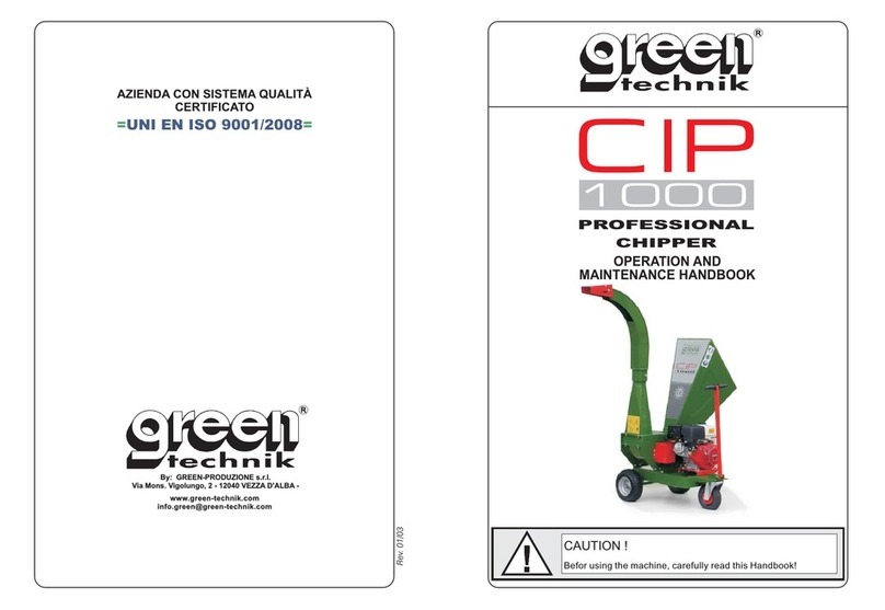
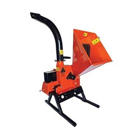
Green Technik CIP 1300 Manual

Rev. 01/03
1300
R
www.green-technik.com
By: GREEN-PRODUZIONE s.r.l.
Via Mons. Vigolungo, 2 - 12040 VEZZA D'ALBA -
R
AZIENDA CON SISTEMA QUALITÀ
CERTIFICATO
==UNI EN ISO 9001/2008
PROFESSIONAL
CHIPPER
OPERATION AND
MAINTENANCE HANDBOOK
CAUTION !
Befor using the machine, carefully read this Handbook!

CIP1300 – Use and Maintenance Manual 1
INSTRUCTION MANUAL CONTENTS
CHAPTER PAR. DESCRIPTION PAGE
01 Information 3
1.1 Preamble 3
1.2 Main warnings 4
02 General information 6
2.1 Introduction 6
2.2 Regulatory references 6
2.3 Purpose of the document 6
2.4 Use of the manual 7
2.5 Compliance with legislation 7
2.6 Keeping the manual 7
2.7 Information for the User 8
03 Technical description of the machine 9
04 Basic parts of the machine and their
positions 10
05 Safety guards and protection devices 11
06 Residual risks concerning the machine 12
6.1 Considerations regarding safety
conditions and residual risks 12
07 Transporting the machine 14
08 Checks 15
09 Starting the machine 16
10 Using the machine 17
10.1 Positioning the discharge conveyor 17
10.2 Control bar 18
10.3 Clogging of the discharge mouth 21

CIP 1300 – Use and Maintenance Manual 2
11 Ordinary maintenance 22
11.1 Adjusting the rotation speed of the rollers 22
11.2 Immobilising the flywheel for maintenance
operations 23
11.3 Adjusting the blades and the counter-
blade 24
11.4 Replacing the blades 25
11.5 Replacing the counter-blade 26
11.6 Sharpening the blades and the counter-
blade 26
11.7 Maintenance of the spark ignition engine 27
11.8 Checking and replacing the hydraulic oil 27
11.9 Replacing the hydraulic filter 27
11.10 Lubricating the flywheel supports 28
11.11 Lubricating the mobile roller running
guides 28
11.12 Lubricating the coupling collar of the
discharge conveyor 28
11.13 Checking and replacing the multiplier oil (PTO
version) 28
11.14 Checking the tension of / Replacing the
transmission belt (Tractor PTO version) 29
11.15 Checking the tension/Replacement of the
transmission belt (motorised version) 30
12 No-Stress Device 31
12.1 Adjustment of the No-stress device
(optional) 31
13 Malfunctions 32
13.1 Possible malfunctions
Causes and solutions 32
14 Pictographs and symbols 33
14.1 Pictographs and symbols 33
15 Electrical system 34
15.1 No-Stress device electrical system (on
request) 34
16 Identification plate of the machine 35
17 Demolition of the machine 36
18 Warranty 37
Warranty slip 38

CIP1300 – Use and Maintenance Manual 3
Chapter 1 INFORMATION
GENERAL INFORMATION CONCERNING THE USE AND
MAINTENANCE MANUAL OF THE CIP1300 CHIPPER
1.1 Preamble
“CAUTION”: This term is used to identify eventualities that can
compromise the integrity of the machine.
These are shown in italics.
“WARNING”: This term, on the hand, is used to identify eventualities
that can compromise the safety of the operator.
These are shown in italics and in some case in bold.
N.B. In all the chapters of this Instruction Manual, the location of the
accessories and the various parts of the machine is always given as in
the diagram shown below.
LEFT SIDE
RIGHT SIDE
BAC
K
FRONT

CIP 1300 – Use and Maintenance Manual 4
Chapter 1 INFORMATION
1.2 Main warnings
The protection guards have been put in place by the
manufacturer to protect the safety of the operator.
During operation the protection guards must not be
removed for any reason..
It is extremely important that no one passes through the
work area of the machine except the operator. The
operator must in no case climb onto the structure of the
machine.
All the maintenance, adjustment and replacement
operations described in this Manual must only be carried
out after stopping the machine.
During blade removal, adjustment and replacement
operations, the operator must wear protective gloves to
avoid possible accidents.
(The manufacturer of the machine supplies a pair)
While processing is being carried out the operator is
required to wear anti-noise muffs given the high noise
level of the production cycle (the sound pressure level
measured at a distance of 1 m exceeds 80 dB).
During processing the operator must wear a pair of
glasses to protect the eyes from sawdust from the
processing.

CIP1300 – Use and Maintenance Manual 5
Chapter 1 INFORMATION
Do not throw away residual hydraulic oil, but dispose of it
in accordance with regulations in force.
Do not, for any reason, interfere with the hydraulic system
of the machine, in particular with reference to regulation of
the oil pressure which is set by the Manufacturer and will
never require further action.
The manufacturer has placed on the machine various
pictographs and symbols, in conformity to current
legislation, so as to warn the operator about residual risks
during operation.
While moving the machine in its travel position, there is
the risk of it overturning.
You must therefore check beforehand the slopes and
unevenness of the route to be taken before attempting to
move the machine.
The path taken must not have a gradient greater than 5%.
Do not allow persons not authorised and not assigned to
the work to have access to the controls of the machine.
It is extremely important that no one passes through the
work area. Any persons not connected with the operation
must not pass through or be in the area of the machine’s
movement.
The machine must only be used by one person at a time.
5%

CIP 1300 – Use and Maintenance Manual 6
Chapter 2 INFORMATION
GENERAL INFORMATION CONCERNING THE INSTRUCTION MANUAL
2.1 Introduction
This Manual is a useful aid to knowing your machine and using it correctly: so you
need to read the Manual carefully before using it.
Every machine is sold together with its own INSTRUCTION MANUAL.
The User is responsible for looking after this Manual for the whole life of the machine
and will see to its destruction only when the machine itself is dismantled.
The Green Produzione. firm will not be answerable for any tampering with this
Manual or for any changes made to the User’s machine, after delivery, and not
provided for in this document.
The Manufacturer reserves the intellectual property rights of this Manual and forbids
its distribution, in whole or in part, in any form (print, photocopy, microfilm, or other
means) and also its elaboration, reproduction or distribution via systems, or legal or
physical persons, without its approval and recording.
2.2 Regulatory references
When putting together the Manual, indications contained in the following documents
have been used:
Directive 2006/42/CE, Appendix and modifications
UNI EN ISO 12100-1 – Safety of machinery: Terminology
UNI EN ISO 12100-2 – Safety of machinery: Technical specifications and
principles
2.3 Purpose of the document
The purpose of the Manual is to provide the User with the instructions and
information that should be scrupulously followed for correct use of the machine and
for protecting the safety of the operator called upon to interact with it.
For this reason the User is invited to:
Make this document available in the workplace and make it known and show it to
all the operators.
Pass on the Manual to later owners of the machine.

CIP1300 – Use and Maintenance Manual 7
Chapter 2 INFORMATION
2.4 Use and conservation of the Manual
This Manual is intended for the User of the machine, those in charge of the moving,
installation, use, supervision and final dismantling of the machine.
The purpose of the Manual is to indicate the intended use for which the machine was
designed and its technical features; it provides instructions for moving it, its proper
and safe installation, its assembly, adjustment and use; it provides information for
carrying out maintenance operations, facilitates the ordering of spare parts and
provides indications concerning possible residual risks.
In particular, it must always be possible to consult it for the following information:
Intended conditions of use of the machine;
The work position occupied by the operator;
Instructions relating to:
Putting the machine into operation, its use, transportation, installation, assembly
and disassembly, adjustment, maintenance and repair work, and any training
instructions there may be.
2.5 Complying with legislation
As well as the rules of this Manual, specific legislative provisions in the field of
accidents at work must be followed.
2.6 Keeping the Manual
The Manual is considered an integral part of the machine and must be kept in good
condition until final disposal of the machine.
The Manual must be kept in a protected place, dry, and sheltered from the sun’s
rays, and must always be easy to find and available for consultation, near the
machine.

CIP 1300 – Use and Maintenance Manual 8
Chapter 2 INFORMATION
2.7 Information for the User
1 - This manual reflects the current technical state of the machine and cannot be
considered inadequate simply because it is later updated on the basis of new
experience.
2 - The Manufacturer reserves the right to update production and manuals, without
being obliged to update previous production and manuals.
3 - The characteristics of materials can be changed at any moment, in accordance
with technical developments, without prior notice.
4 - Where the machine is without an electric control and protection device (on board
electric panel) , the Manufacturer does not assume any responsibility concerning
safety problems deriving from electrical parts not conforming to what is advised
and/or laid down.
In any case compliance with all electricity related Laws and Regulations for
equipment the machine is fitted with shall be exclusively the responsibility of the
Customer, who shall install it to the required standard and fit for the purpose for
which it is to be used.
5 - The Manufacturer considers itself relieved of any responsibility where the machine
has been put to:
Qimproper use;
Quse by untrained staff;
Quse contrary to what is set out in this Manual;
Quse contrary to Regulations and Legislation currently in force;
Quse with a mains power supply defect;
Quse with serious lack of specified maintenance;
Quse with modifications or work carried out not explicitly authorised by a written
note from the Manufacturer;
Quse of non-original spare parts or spare parts not specifically defined for the
model;
Quse with total or partial failure to observe the instructions contained in this
Manual.
6 - The general sales warranty is void in case of:
Qpoor conservation;
Qmishaps through incorrect use;
Quse by inexperienced personnel;
Qexceeding performance limits;
Qexcessive mechanical and/or electrical and hydraulic stress
Quse under the non-optimal conditions described in point 5.
Any requests for further copies of this document must be formalised with a purchase
order forwarded to Green Produzione.

CIP1300 – Use and Maintenance Manual 9
Chapter 3
TECHNICAL DESCRIPTION OF THE MACHINE
The CIP 1300 chipper has been designed for the reduction in volume of
pruning residues, branches or woody debris into small size fragments.
The material introduced into the loading mouth is pulled by two rollers against
the cutting disk.
The two pulling rollers are powered by independent speed-adjustable hydraulic
motors.
On the cutting disk, that rotates at a speed of 1500 rpm, two blades are
assembled that reduce the material to splinters of a 5-20 mm. length and a
counter-blade, fixed to the structure, that further reduces the splinters into
“chips”.
The “chips”, through the centrifugal action of the cutting disk, are projected into
a discharge conveyor.
The conveyor can be pointed in the required direction of discharge.
Technical features
•size of loading mouth mm 960 x 670
•MAX shreddable diameter mm 130
•diameter of flywheel mm 680
•thickness of flywheel mm 25
•blades n° 2
•rotation speed of flywheel (max) g/min. 1500
•length of shredded material mm 6 ÷ 12
•diameter of feeder rollers mm 120 -120
•maximum width between the rollers mm 140
•power of independent motor (YANMAR / HONDA) kW 8,2 ÷ 13.5
•hourly production m33 ÷ 5
•airborne noise produced by the machine ( 1 ) Db (A) ?
•weight Kg 420 ÷ 490
( 1 ) The MAX noise level indicated is measured in the operator area, during work
?Greater than 85 dB: the use of muffs is compulsory

CIP 1300 – Use and Maintenance Manual 10
Chapter 4
BASIC PARTS OF THE MACHINE AND THEIR POSITIONS
DISCHARGE DEFLECTOR
LOADING
MOUTH
CONTROL
BAR
CHASSIS
ENGINE
LAUNCH
T
U
BE
TOW BAR

CIP1300 – Use and Maintenance Manual 11
Chapter 5 SAFETY PROTECTION DEVICES
PROTECTION GUARDS AND DEVICES ADOPTED FOR REASONS
OF SAFETY
CAUTION:
The guards have been put in place by the manufacturer to
protect the safety of the operator.
During operation the guards must not be removed for any
reason.
A) Fixed guards to close off the flywheel
rotation area.
B) Hydraulic motor side protection case.
C) Hydraulic pump rear protection case.
D) Transmission belt fixed guard (PTO version
– CIP 1300PTO).
E) Transmission belt fixed guard (Motorised
version – CIP 1300Y18 - 1300H24)
N.B.: the guards must in no way be
removed: when carrying out
maintenance switch off the engine
and remove the key from the control
panel or, for the P.T.O. version,
disconnect the cardan shaft
A
E
D
C B

CIP 1300 – Use and Maintenance Manual 12
Chapter6 RISKS
RESIDUAL RISKS CONCERNING THE MACHINE
6.1 Considerations regarding safety conditions and residual risks
To be able to work in conditions of maximum safety, and to avoid creating dangerous
situations, the norms of behaviour are listed that must be followed by the operator to
avoid accidents while using this machine.
RESIDUAL RISK REFERENCE
CHAPTER
During processing the guards must
not be removed for any reason. CHAPTER 5
Protection guards
and devices adopted
for safety reasons
In particular the fixed guards that
close off moving parts, whether of
transmission or work, must not be
removed.
During installation, check that the
ground is sufficiently hard to ensure
the stability of the machine.
Pay the greatest attention that no
one passes through the crane’s
area of movement, to avoid the
possibility of accidents occurring to
personnel during the movement of
a suspended load.
CHAPTER 7
Transporting the
machine

CIP1300 – Use and Maintenance Manual 13
Chapter6 RISKS
CAUTION: Read carefully the instructions in this manual before setting
the machine in motion.
RESIDUAL RISKS REFERENCE
CHAPTER
During blade adjustment and
replacement operations you must
wear protective gloves to avoid
possible accidents.
CHAPTER 13
Blade replacement.
During processing no one must
move about or stay in the vicinity of
the machine or carry out
maintenance work.
CHAPTER 12
Using the machine.
Before any adjustment or
maintenance operation, switch off
the engine and remove the key
from the control panel.
CHAPTER 14
Ordinary and
extraordinary
maintenance
Never rotate the flywheel with your
hands. Before putting your hands
near the blades or the counter-
blade make sure the flywheel is
completely still.
CHAPTER 10
Take all the necessary precautions
to avoid being caught up with
material that is being pulled inside
the machine. Should this happen
invert the direction of rotation of the
rollers by pushing forward the
control handle of the distributor..
CHAPTER 10

CIP 1300 – Use and Maintenance Manual 14
Chapter 7 TRASPORTATION
TRASPORTING THE MACHINE
WARNINGS :
Any persons not connected with operations must NOT pass through or
be in the machine’s area of movement, to avoid being struck by the
machine when it is suspended in the air.
Pay particular attention that the lifting speed is such as will avoid
dangerous swaying of the machine and the danger of the lifting cable
breaking.
Where the lifting or movement is carried out with a crane, the size of
lifting cable must be suitable for the weight of the machine, in order to
operate in conditions of complete safety.
When the machine has to be placed onto
a means of transport, it is possible to lift it
by means of a crane.
To carry out the crane manoeuvre in
safety the following procedures must be
followed.
•check the overall weight of the
machine (consult chapter 3:
“Technical Features”) and verify the
lifting capacity of the hooks (equipped
with safety devices) and the lifting
ropes (G)
•Attach the hooks of the ropes to the
plates welded to the structure of the
machine (P)
•Lift the machine from the ground and
position it on the means of transport.
G
P

CIP1300 – Use and Maintenance Manual 15
Chapter 8 CHECKS
CAUTION:
It is extremely important for persons not connected with the
processing to be away from the work area.
Check that the machine is equipped with warning notices.
W A R N I N G S
Check that:
The operator is qualified to use the machine.
The operator is well acquainted with how to use the machine
before setting it in motion.
The operator and the auxiliary staff are aware of the accident
prevention regulations.
The operator is at least 18 years of age.
The operator wears close-fitting clothes.
The operator wears protection equipment for ears and eyes, and
uses protective shoes and safety gloves.

CIP 1300 – Use and Maintenance Manual 16
YANMAR
ENGINE
Chapter 9 STARTING
STARTING THE MACHINE (version with independent motor)
CAUTION:
The starting key of the machine must be kept by the operator
whenever the machine is stopped. Leaving the key inserted in the
starting panel involves the risk of the machine being started by
third parties.
Start the machine following the procedure shown in the specific handbook of the
engine that is fitted.
INSTALLATION (version with three point attachment)
WARNING:
Check that the inclination of the cardan shaft when working at PTO
540 rpm does not exceed 16° and at PTO 1000 rpm does not exceed
9°.
Connect the machine to the three
attachment points of the tractor. Insert the
security pins (B,C,D).
Connect the cardan shaft to the power take-
off of the tractor and to the entry shaft of the
machine (A).
Check that the locking pins have engaged.
N.B.: Check that the cardan shaft has a
minimum axial play of 10 cm (G).
Check the rotation direction (R).
Immobilise the tractor with the parking
brake. If the machine is provided with a
“No-Stress” device, connect the cable of the
instrument to the 12V battery.
Slowly start up the tractor and bring it up to
the necessary revs ((max 540 revs/min.).
HONDA
ENGINE
G
A
SENSO ROTAZIONE
ALBEROENTRATA
GRUPPOD’ANGOLO
PTOTRATTORE
R
B
A
C
D
ROTATION DIRECTION
TRACTOR PTO ANGLE UNIT
ENTRY SHAFT

CIP1300 – Use and Maintenance Manual 17
Chapter 10 USING THE MACHINE
CAUTION:
It is extremely important that nobody passes through the
work area of the machine except the operator.
CAUTION:
Danger of injury
To carry out the operations described it is obligatory to wear
protective gloves, glasses or a protective visor, ear muffs
and safety shoes.
10.1 Positioning the discharge
conveyor
After putting the machine into the
working position, the position of the
discharge conveyor needs to be
adjusted to direct the outflow of
chipped material.
Slacken knob (M)
Turn the conveyor into the desired
direction, grasping the lever (L). (The
conveyor can rotate on itself 360°).
Tighten knob (M).
Slacken knob (P).
Adjust the inclination of the deflector
(D) positioned at the end of the
conveyor.
Tighten knob (P).
P
D

CIP 1300 – Use and Maintenance Manual 18
Chapter 10 USING THE MACHINE
CAUTION:
It is extremely important that nobody passes through the
work area of the machine except the operator.
CAUTION:
CAUTION! Never put your hands near the entry
section.
Take all the necessary precautions to avoid being caught up
with the material that is being pulled inside the machine.
Should this happen invert the direction of rotation of the
rollers by pushing forward the control handle of the
distributor.
10.2 Control bar
The device allows the operator to
control the 2 feeder rollers.
Position 3 “FORWARD”
The rollers rotate and pull the material
towards the working disk.
Position 2 “STOP”
The rollers stop and prevent the
material from advancing forward
towards the working disk.
Position 1 “BACKWARDS”
The rollers rotate in the opposite
direction, taking material away from the
working disks.

CIP1300 – Use and Maintenance Manual 19
Chapter 10 USING THE MACHINE
CAUTION:
It is extremely important that nobody passes through the
work area of the machine except the operator.
CAUTION:
Danger of injury
To carry out the operations described it is obligatory to wear
protective gloves, glasses or a protective visor, ear muffs
and safety shoes.
CAUTION:
CAUTION! Never put your hands near the entry
section.
Take all the necessary precautions to avoid being caught up
with the material that is being pulled inside the machine.
Should this happen invert the direction of rotation of the
rollers by pushing forward the control handle of the
distributor.
Start the engine following the
procedures shown in the specific use
and maintenance handbook and let it
warm up for a few minutes at low revs.
Pull the control bar of the distributor
into position (3) “FORWARDS” The
feeder rollers are made to rotate (A).
Introduce material to be shredded into
the loading hopper.
The progress of material towards the
cutting disk is automatically regulated
at the moment of contact with the
hydraulic feeder rollers.
N.B.: Take all the necessary precautions to avoid being caught up with the
material that is being pulled inside the machine.
Should this occur invert the direction of rotation (B).of the rollers by
pushing the control lever of the distributor into the “BACKWARDS” (1)
position.
A
B
Table of contents
Other Green Technik Chipper manuals