Fort Visio Prime User manual

www.fort-fr.com
BA01-015_1-0
Operating instructions
Revision: 07/2011
:: VISIO PRIME Home Inspector
:: VISIO PRIME Inspector

reface :: reface
A system constructed strictly according to the
practical demand of our customers and users.
To obtain maximum benefit and for a secure
and safe operation please read the manual
before starting up and using the instrument.
When used proper, this system will be offering
you excellent inspection capabilities over a long
lifetime.
In order to obtain the economic advantages of
your system even in the long run, you ought to
read and follow the following advice, tips and
warnings carefully. The observance of these
instructions serve the purpose of your own
safety as well as the safety of those in the work
field of the device.
All tips, code of behaviour, suggestions for
measures to be undertaken, advice, warnings
and instructions are exclusively valid for the
operation of VISIO RIME and not for devices
by other manufacturers.
For questions, which have not been answered
by this instructions manual, your dealer and/or
the manufacturer are gladly available for advice.
indly contact us even if you have suggestions
for the improvement of this manual or the product.
For contact details please consult the last page.
Thanks for choosing a FORT®product for your
inspection service
Congratulation to your new
VISIO RIME video system!
www.fort-fr.com
Warning
Before the initial operation, this instructions
manual must be completely read and under-
stood by the user in order to prevent damage
and danger to life and property through the ope-
ration of the video endoscope system (the de-
vice). The operation of the device without the
understanding of the instructions manual is not
allowed under any circumstances. The device
has to be used exclusively by trained operators.
It is absolutely not suited for any medical or ve-
terinary application and must never be opera-
ted by private users.
For a generally non-destructive operation of the
device, beside the safety of the personnel and
environment, an extensive knowledge of the de-
vice, the inspection technology, the safety in-
structions as well as the field of application are
absolutely necessary!
The device must never be connected to electric
mains, if you have not understood this instruction
including safety warnings or even if you have not
understood individual sections or if you cannot
or do not wish to use the device in
accordance with the regulations.
FORT®is not liable under any circumstances for
the consequences of misinterpretation or faulty
inspection results, which were achieved with the
device.
FORT®shall not be liable under any
circumstances for the loss of inspection data.
FORT®shall not be liable under any
circumstances if device parts are left behind in
the inspected plant inadvertently.
www.fort-fr.com
Compulsory instructions
for a safe start-up in
accordance with
regulations. Reading
beforetheinitial operation
is compulsory!
For compulsory attention:
Warning against risk of injury or
loss of life to humans
Warning against significant risk of
damage to device and plant
Warning against fatal electric shock
Warning against life-threatening
explosion risk
Warning against life-threatening
fire risk
Warning

Warning
www.fort-fr.com
The device must never be opened by the user at any place. Life-threatening electric currents are used
or generated in the device; in particular, the device must never be used with the housing open. The de-
vice must never be used when there are audibly loose parts inside the device.
Before start-up, the device must be acclimatized according to the ambient temperature.
This is valid in particular for cooled devices, wherein condensate accumulation during warm-up
can lead to destruction and damage due to electric spark over.
Never operate the device under conditions which do not comply with the operating conditions
or storage conditions described in the instructions manual!
The device must be checked annually by the manufacturer or an authorized third party for
compliance with the electrical safety instructions obligatory at the usage site and conformance
with the as-delivered condition of the device. The device must not be connected to the electric
supply mains or otherwise operated after the ascertainment of a defect or any deviation from the
as-delivered condition. This is valid, in particular, if the device has tumbled or fallen down or was
exposed to a liquid.
The device must never be operated in operating environments which are vulnerable to explosion
or fire risk. The device is not equipped with safety devices or acceptance for operation in
environments vulnerable to explosion or fire risk. An impermissible employment in environments
susceptible to explosion or fire leads unavoidably to a device-induced life-threatening explosion
and to a fire in the plant. The operator is obliged to check the plant for substances vulnerable to
explosion or fire before every new start-up of the device.
:: Warning
Never allow the device to be operated without supervision.
For safety reasons, it is necessary to switch-off the machine during pauses.
Never operate the device in radio-actively contaminated environment!
Never expose the probe to ionizing radiation of any type!
The device must be transported exclusively in the transport case conceived for it by the
manufacturer. The device and the corresponding accessories must be packed in the transport
case only according to the instructions at hand.
For increasing your own safety against electric shocks with risk of injury or loss of life, the
device must always be connected and operated via a residual current circuit breaker system
or an isolating transformer. This can in any case be a compulsory condition depending upon the
operating environment. For this, consult your responsible safety in-charge or the accident
protection measures in force in your respective country.
The use of too long power extension cords is life-threatening and forbidden (max. 25 m in case of
a supply line made of copper 3 x 1.5 mm2). Hereby, a life-threatening loss of the protective function
of the upstream safety element is possible. At the same time, voltage differences of the earth
potential as compared to the displaced reference point of electric output (bridged by a too long
extension cord) could cause dangerous electric currents on contact with the device housing or
impermissibly high equalizing currents at the probe. In case of uncertainties, consult your on-site
electrical expert.

Warning
www.fort-fr.com
Exclusively the FORT®accessory articles or spare parts described in this instructions manual may be
used in connection with the device. Always consult and follow the national and international
operations and safety regulations, Norms or regulatory authority’s advice.
The device can be connected to the public electric supply mains through a ‘IEC-plug lead’ included
in the delivery or a ‘IEC-plug lead’ which complies with the local socket standards.
The system accepts faultlessly all power supplies known worldwide with alternate currents of
96 VAC to 246 VAC at 46 to 60 Hz. For safe operation, the device needs a reliable potential earth (PE)
connection. In case of doubt, an expert or the manufacturer must be consulted.
The minimum output supplied by the power connection can be derived from the device
specifications contained in the instructions.
:: Warning
When operating the device outside the permissible operating conditions or with destruction caused
by usage which deviates from the instructions, non-compliance with the operating conditions or
through the usage of non-original spare parts or accessories as well as through impermissible
opening of the device, the guarantee obligation or the guarantee commitment by the supplier or
manufacturer lapses, in principle.
When operating the device outside the permissible operating conditions or with destruction caused
by usage which deviates from the instructions, non-compliance with the operating conditions or
through the usage of non-original spare parts or accessories as well as through impermissible ope-
ning of the device, the guarantee obligation or the guarantee commitment by the supplier or manu-
facturer lapses, in principle.
Never connect a triploar plug to a bipolar socket! Avoid any contact between VISIO PRIME
(and all working equipment) and components carrying electrical charges.
The system must be earthed properly in case of an electrified application in relationship to the
ground. If impossible, connect the system to the application or the ground (depending on which one
the user needs to touch). The user needs to be isolated against the current path of the earthed path.
Never insert the probe in plant parts the contents of which are unknown!
Never bring the probe in contact with corrosive substances of any kind (acid or alkali).
Risk of damage and injury while manipulating the probe. Never bring the probe in contact
with solvent containing liquids! Risk of damage!
The video probe of the device must never be used in or in the vicinity of apparatus or equipment,
which are partly or fully energized by electric current of any type (e.g. transformers, motors,
generators, switchboards etc.). The metallic mesh of the probe conducts electricity and dangerous
currents are transmitted during every contact or even short-circuits can be triggered in the plant.
The device must never be operated with damaged video probe. There is a risk of damage to hand
due to the metallic protective mesh (suggestion: always wear work gloves for protection).
At the same time, there is a danger that liquids might penetrate the probe and thereby impair the
functioning permanently or might cause a life-threatening electric shock to the operator!
Even the use of a slightly damaged probe can quickly lead to the total destruction of the probe
due to destruction of the light fibres or the electric conductors lying inside. The operation of a
damaged probe is impermissible within the area of jurisdiction of the European Union, since the
regulations on emission of electro-magnetic radiation can no longer be adhered to with safety.

Warning :: Warning
www.fort-fr.com
Do not insert the insert tube into any flammable gas or liquid (such as a fuel tank) to avoid dangers.
Avoid direct exposure to sunlight for long periods of time.
Please do not use the VISIO PRIME in a medical facility or on an airplane, as the wireless signal
may interfere with other critical equipment nearby.
Do not heavy force to screw the probe head further than half a screw for focussing. Screwing
further using force damages the entire probe head and optics!
Never insert the probe in plant parts, if weld or cutting work is being undertaken simultaneously or
soon. Likewise, the probe must never be inserted if further inspection procedures like eddy current
or radiography tests are being undertaken on the same plant part. Never insert the probe in plant
parts, which are not fully switched-off (e.g. danger from rotating plant components) or cooled down.
Never look directly at the light emission in the camera head. There is danger of lasting
eye injury or at least a long-lasting eye irritation with accidental consequences through a
temporarily restricted power of vision.
Avoid tight coils or even knots in the tube. Do not step onto the insertion tube or camera head.
Do not smash the camera head with it’s optics onto the floor or cause any other possible impact to
the instrument. This can damage your probe!
Do not use the probe for transporting the system! This can damage your probe!
To transport the system use the handle on the control unit.

Content
www.fort-fr.com
:: Content
1 Structure and start-up 01
1.1 Removal from the transport case 01
1.2 Accessories 05
1.3 Initial operation 06
1.4 Manual focussing 06
3 Accessory equipment 09
3.1 Optional side tip adapter 09
3.2 Optional USB auto charger 09
3.3 Optional video RCA connector cable 09
3.4 Optional Mini USB to USB connector cable 09
3.5 Optional VISIO PRIME hook tool 09
3.6 Optional VISIO PRIME magnet tool 09
5 Warranty, technical data and conformity 11
5.1 Warranty 11
5.2 Excluded from the warranty regulation 11
5.3 Scope of services and definition 11
5.4 Responsibility 11
5.5 Repair location 11
5.6 Date of effect 11
5.7 Application conditions 11
5.8 Acceptance of jurisdication 11
2 Operation - User Interface - Documentation 07
2.1 System modes 07
2.2 Preview mode 07
2.3 Browse mode 07
2.4 Manual mode 07
2.5 Operation 07
4 Maintenance, care and repair 10
4.1 Maintenance by the manufacturer 10
4.2 Transport 10
4.3 Customer service 10

www.fort-fr.com
1 Structure and start-up 01
1.1 Removal from the transport case 01
1.1.1 Specifications 03
1.1.2 Control unit 04
1.2 Accessories 05
1.3 Initial operation 06
1.4 Manual focussing 06
1 Structure and start-up
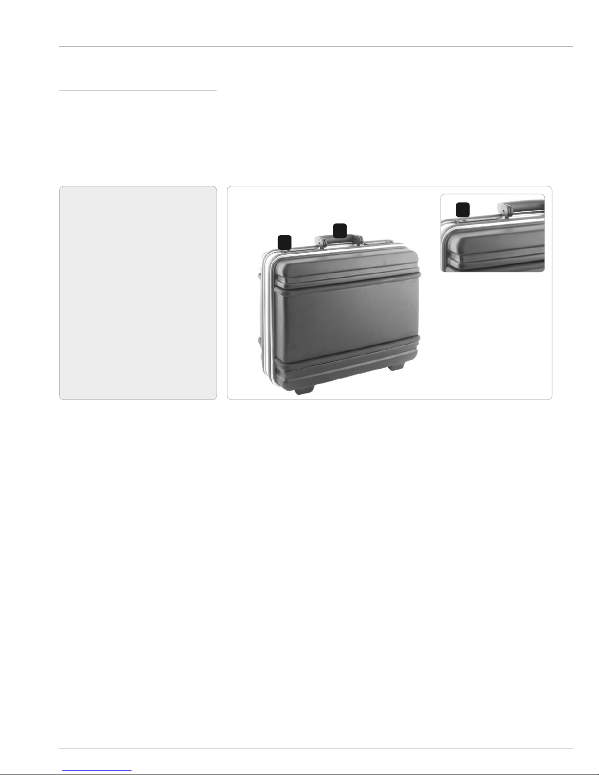
1.1 Removal from the transport case
Before opening the optional transport case,
check the container for possible transport
damages.
Dimensions: (H) 415 x (W) 465 x (D) 190 mm; PE;
Weight empty: 3,25 kg.
01
www.fort-fr.com
1Carry handle
2Push here to open the transport case
1.1a
1
2
:: 1.1 Removal from the transport case
2
1.2a

1 Structure and start-up
Memorize the location of each part during re-
moval to proceed later in reverse sequence.
02
www.fort-fr.com
1TFT screen 3.5’’
2Video recording
3Photos and videos replaying
4Photos and videos replaying
5General switch ON/OFF
6Menu
7Exit
8Photo saving
9Articulation wheels
10 Articulation brake
11 SD memory
12 Composite video out
13 Charger connection
14 Mini USB connection
15 Adjustment LED illumination
10
1
:: 1.1 Removal from the transport case
13
15
12
9
11
14
2 3 4 5 6 7 8

1 Structure and start-up
1.1.1 Specifications
03
www.fort-fr.com
:: 1.1 Removal from the transport case
Specifications VISIO RIME Home Inspector
Working length 2meter, 3 meter, 6 meter |6.5 ft, 9.8 ft, 19.7 ft
Working diameter 6 mm |0.24”
Articulation All way 120°
Insertion tube material Special coated polyurethan
Illumination High power LED fiber Hybrid
Display TFT 3,5 inch
Image recording Standard JPEG
Video recording Digital MPEG2
Image and film storage SD card included
Connectors USB 2.0, DC power
Video output Composite video out
Weight Less than 1 kg |Less than 2.20 lbs
Storage temprature -40°C to +70°C |-40°F to +158°F
Operation temperature -10°C to +60°C |+14°F to +140°F
Direction of view (DOV) 0° forward / 70°, 90°, 110° side view mirror (optional)
Range of view Focus 3 mm (0.12”) to ∞ (infinity variable with the “Easy Focus” optic system)
Zoom Digital 1,5x
Transport case Robust with special foam inlay
Waterproof Insertion tube fully immersible and waterproof
Specifications VISIO RIME Inspector
Working length 2 meter, 3 meter, 6 meter |6.5 ft, 9.8 ft, 19.7 ft
Working diameter 6 mm |0.24”
Articulation All way 120°
Insertion tube material Tungsten
Illumination High power LED fiber Hybrid
Display TFT 3,5 inch
Image recording Standard JPEG
Video recording Digital MPEG2
Image and film storage SD card included
Connectors USB 2.0, DC power
Video output Composite video out
Weight Less than 1 kg |Less than 2.20 lbs
Storage temprature -40°C to +70°C |-40°F to +158°F
Operation temperature -10°C to +60°C |+14°F to +140°F
Direction of view (DOV) 0° forward / 70°, 90°, 110° side view mirror (optional)
Range of view Focus 3 mm (0.12”) to ∞ (infinity variable with the “Easy Focus” optic system)
Zoom Digital 1,5x
Transport case Robust with special foam inlay
Waterproof Insertion tube fully emersible and waterproof

1 Structure and start-up
04
www.fort-fr.com
1.1.2 Control unit
Each button performs a unique function depen-
ding upon the Mode in which the system is being
operated.
:: 1.1 Removal from the transport case
Button review mode Browse mode Manual mode
Start and stop video
recording Return to Preview mode Return to Preview mode
Switch to Browse mode
to view images and vi-
deos
Move to previous image
or video
Move up through the
main manual
Switch to Browse mode
to view images and vi-
deos
Move to next image or
video
Move down through the
main manual
Switch the inspection
system on/off
Switch the inspection
system on/off
Switch the inspection
system on/off
Enter Manual mode Delete image / video Execute selected
command
Return to Preview mode Return to Preview mode Return to Preview mode
Snapshot (JPG) View next image / pause
or play video
Display various data for
repair
+ LED illumination + LED illumination + LED illumination
- LED illumination - LED illumination - LED illumination

1 Structure and start-up
05
www.fort-fr.com
1.2 Accessories
Scope of delivery:
3 4
5
2
1VISIO PRIME
2SD card
3Battery charger
4Focussing tool
5Transport case
6Optional side tip adapter 70°, 90°, 110°
7Optional USB auto charger
8Optional video RCA connector cable
9Optional Mini USB to USB connector cable
10 Optional VISIO PRIME hook tool
11 Optional VISIO PRIME magnet tool
12 Optional accessory case
incl. all available accessories
Some accessories are not included in delivery
and must be purchased additionally.
Therefore, please contact your local sales
representative.
:: 1.2 Accessories
6
1011
789
1
12

1 Structure and start-up
1.3 Initial operation
1. Press
for 3 seconds until the image is displayed on the
screen.
2. Aim the camera lens at the selected object.
Press
to capture a JPG image or
to begin recording a ASF video.
1.4 Manual focussing
To focus the probe for different inspection requi-
rements, use the focussing tool (page 05, 4. Fo-
cussing tool). Continue as showed in pictures 1.4a
to 1.4b.
Insert the pins of the focussing tool into the fix-
ture of the probe head (picture 1.4b).
06
www.fort-fr.com
:: 1.3 Initial operation
NOTE! Do not remove the SD card during
capturing photos or video. This can cause a
loss of the image or video and may damage
the SD card!
NOTE! Do not heavy force to screw the probe
head further than half a screw for focussing.
Screwing further using force damages the
entire probe head and optics!
NOTE! Video recording requires an SD card
with fast writing speed. We recommend 80x
(or above) writing speed SD cards for better
video quality!
1.4a
1.4b
Fixture
Pins

www.fort-fr.com
2 Operation - User Interface - Documentation 07
2.1 System modes 07
2.2 Preview mode 07
2.5.1 Recording images 08
2.5.2 Recording videos 08
2.5.3 Viewing images and videos 08
2.5.4 Deleting specific data (Browse mode only) 08
2.5 Operation 08
2.3 Browse mode 07
2.4 Manual mode 07
2.4.1 Deleting data 07
2.4.2 Video output 07
2.4.3 Date and time 07
2.4.4 Language 07
2.4.5 Video format 07

2 Operation - User Interface - Documentation
2.1 System modes
The FASTA provides three simple working
modes: Preview mode, Browse mode and Manual
mode.
2.2 review mode
The Preview mode is activated as soon as the unit
is turned on. The image received by the camera is
displayed in real time on the video monitor. The
user can capture images and record videos while
working in the Preview mode.
2.3 Browse mode
In the Browse mode, users may view images and
videos, and conduct basic file maintenance.
2.4 Manual mode
In the Manual mode, users may customize their
setup preferences.
Press
in Manual mode to execute desired commands.
2.4.1 Deleting data
Press
or
to select DELETE ALL and confirm the command
by pressing
Exit by pressing
2.4.2 Video output
This command will send the video signal out
through the AV port. The monitor will turn black
until you execute this command again.
2.4.3 Date and time
Use
or
to select Year/Month/Day or Hour/Min/Sec.
Press
to increase the number, or press
to decrease. Select “Display ON” to print the date
on the photo.
2.4.4 Language
Use this command to select the desired
language.
2.4.5 Video format
Select your video format.
07
www.fort-fr.com
:: 2.1 System modes
NOTE! The system returns to review mode
automatically after 10 seconds without any
response in Manual mode!

2 Operation - User Interface - Documentation :: 2.5 Operation
2.5 Operation
2.5.1 Recording images
Press
during Preview mode to record an image.
Additionally, continue pressing the PHOTO but-
ton to show the recorded image.
2.5.2 Recording videos
Press
to start video recording.
Press
again to stop recording.
2.5.3 Viewing images and videos
Press
or
during Preview mode.
Press
or
again to view the oldest or second to last
image/video.
2.5.4 Deleting specific data
(Browse mode only)
Enter the Browse mode, then press
or
to locate the image or video
you wish to delete.
Press
To select your option, press
or
Press
to execute your selected option or press
to cancel.
08
www.fort-fr.com
Image Status: Returns to preview mode au-
tomatically after photo is taken.
Image Status: Display the latest image/video.
Image Status: “Delete YES or NO” options
Image Status: The selected option flashes.
Image Status: RECORDING sign will appear
at the left bottom of the screen.
Image Status: All files will be stored accor-
ding to the time sequence of image cap-
ture/video recording
NOTE! User may return to review mode
anytime by pressing RECORDING button re-
gardless of working under Browse mode or
Manual mode!
NOTE! : When viewing videos, the video will
be displayed automatically until it ends and
then the next image or video will be dis-
played!
Image Status: RECORDING sign disappears

www.fort-fr.com
3 Accessory equipment 09
3.1 Optional side tip adapter 09
3.2 Optional USB auto charger 09
3.3 Optional video RCA connector cable 09
3.4 Optional Mini USB to USB connector cable 09
3.5 Optional VISIO PRIME hook tool 09
3.6 Optional VISIO PRIME magnet tool 09

3 Accessory equipment :: 3 Accessory eqipment
3.1 Optional side tip adapter
The optional side tip adapters (70°, 90° and 110°)
need to be mounted on the tip of the probe head.
3.2 Optional USB auto charger
Connect the USB auto charger USB cable with
the charger connection of your VISIO PRIME
(page 02, 13. Charger connection). Connect the
USB auto charger module with the car’s ciga-
rette-lighter.
3.3 Optional video RCA connector cable
Connect the video RCA connector cable with the
Composite video out of your VISIO PRIME (page
02, 12. Composite video out) and the external
monitor.
3.4 Optional Mini USB to USB
connector cable
Connect the video Mini USB to USB connector
cable with the Mini USB connection of your
VISIO PRIME (page 02, 14. Mini USB connection)
and the PC/Laptop for direct data transfer.
09
www.fort-fr.com
3.5 Optional VISIO RIME hook tool
Mount the optional VISIO PRIME hook tool as dis-
played in picture 3.5a.
3.6 Optional VISIO RIME magnet tool
Mount the optional VISIO PRIME magnet tool as
displayed in picture 3.6a.
NOTE! ay attention to keep the inside
structure of the side tip adapter free of dirt!
NOTE! By connecting an external monitor to
your VISIO RIME, the screen will only be
shown on the monitor!
NOTE! Additionally, you can trasfer your
data by connecting the SD card to a card rea-
der!
3.5a
3.6a

www.fort-fr.com
4 Maintenance, care and repair 10
4.1 Maintenance by the manufacturer 10
4.2 Transport 10
4.3 Customer service 10
Table of contents


