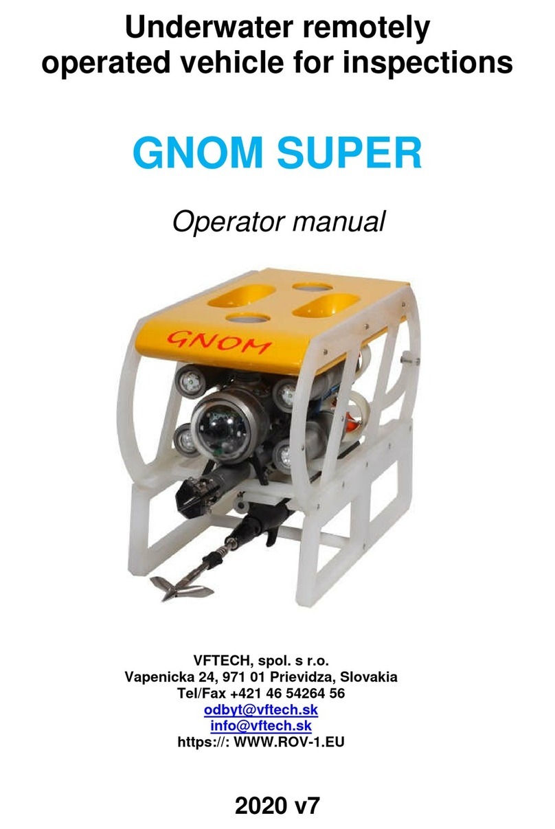
VFTech GNOM Super PRO User manual

Underwater remotely
operated vehicle for inspections
GNOM Super PRO
Operators manual
VFTECH s.r.o.
Vapenicka 24, 971 01 Prievidza, Slovakia
Tel/Fax +421 46 54264 56
http://www.vftech.sk

v03/2017
2
TABLE OF CONTENTS
Warning !!!
Voltage on cable 180VDC!
Do not touch the cable in a water during operation!
If any damages happen on a shield of cable it must be repaired or
changed !
Attention! AC power maximum 240V !
1. Description 3
1.0 Introduction 3
1.1 Purpose 4
1.2 Design 5
1.3 Technical specifications 7
2. User’s manual for operation with GNOM 8
3. Keys and Buttons at the control panel 14
4. Screen modes 17
5. Calibration 18
6. Maintenance operation 19
7. Safety requirements 20
8. Warranty statement 21
9. Examples of linking modules 22
10. Appendix 23

v03/2017
3
1. DESCRIPTION
1.0 INTRODUCTION
ВНИМАНИЕ!
Warning!
Achtung!
ELECTRIC DANGER 230V/50Hz
Read carefully this instruction
Ask for assistance of a qualified electricians
Underwater remotely controlled vehicle GNOM is connected to AC 230 V / 50 Hz power supply and
poses a potential hazard (electric shock or fire).
Underwater vehicle "GNOM" belongs to the category of electromechanical products.
Installation, operation and maintenance of these products must be performed by qualified and
competent persons, acquainted with this user manual.
Buyers and attendant facilities "GNOM" must abide operating instructions to ensure their own
safety, the safety of people around and to minimize the risk of potential damage of the module
when working under water.
The guide should always be available to all persons involved in organization and implementation of
operations with the GNOM modules.
Unless the assembly GNOM is used according to manual, then it meets international standards:
Safety IEC 60065 (GOST R IEC 60065-2002)
Electromagnetic compatibility IEC 61000-6-1-99 (GOST R 51317.6.1, GOST R 51317.6.3-99)
In addition to these general principles, the laws and regulations applicable in each country as well as
the rules and regulations applicable at the place of work with the underwater modules should be
respected.
Sale or transfer of module "GNOM" to the other person may be exercised only with delivery of
operating instructions. In this case the potential risks in the operation of the gnome passes to the
buyer (attendants).
This guide GNOM together with operating instruction is intended to inform the user in order to
ensure correct and safe use of GNOM.

v03/2017
4
1. DESCRIPTION
1.1 PURPOSE
The product "GNOM" is designed for underwater works. Inspection and control of premises
located under water in coastal and inland waters, as well as in the control of reservoirs and
water works.
The main advantage of remotely operated vehicle is that you can see underwater full-
featured video
Command of underwater module is executed by operator from the shore (or the vessel) by
means of the control module, which is a part of the kit.
The modern computer and telecommunication technologies are used in the device, and
made it easy in handling, compact, light and inexpensive.
These solutions allowed to use thin (only 10 mm diameter) and flexible communication
cable for transmission data, power and video signals to/from vehicle. The special Kevlar
threads have been used to improve the cable's tensile strength. Because of this fact, the
device keeps the highest degree of stabilization what is very important for inspections. The
vehicle has a good maneuverability and can easily turn on the spot.
High-effective electric motors with magnetic couplings and hi-tech electronics are used in
the vehicle, provide the fast speed of the GNOM with low power consumption.
One of the most important features of this device is a possibility to operate it from PC and
via Lan/Internet.
The GNOM, in essence, an underwater helicopter with the video-camera which moves in
any direction according to the operator's instructions.
For update info please visit our web site www.vftech.sk

1.2 DESING
ROV GNOM S
uper PRO
1 – ROV GNOM Super PRO
, 2
ROV GNOM S
uper Pro
1 – ROV GNOM Super PRO
2 – Control box with joystick
3 – Hand reel with tether
4 – Joystick
5 – LCD monitor
WARNING:
Producer reserves the right to change the scope of delivery with
maintaining the functionality and technical specifications for
sets
Main features
Color High Resolution video
3 (5)
thrusters, adjustable speed
Slow/fast mode, tilting vehicle mode
LEDs lights
Flexible thin cable
Device is fitted out with the depth gauge, autodepth mode
Heading (co
mpass), autoheading
Videotext overlays with graphics
On screen menus
Easy game joystick control
Digital data channel
PC interface, Lan/Internet web video/control (option)
All packed in 2 cases, hand carried
v03/2017
1. DESCRIPTION
uper PRO
full complete set + options
, 2
– Control box waterproof case integrated, 3 –
hand reel with sleep ring, 4
5 –LCD monitor 15", 6 – grabber
uper Pro
basic complete set
WARNING:
Producer reserves the right to change the scope of delivery with
maintaining the functionality and technical specifications for
Color High Resolution video
-
camera with tilt servo and digital zoom
thrusters, adjustable speed
Slow/fast mode, tilting vehicle mode
Device is fitted out with the depth gauge, autodepth mode
mpass), autoheading
Videotext overlays with graphics
Easy game joystick control
Digital data channel
PC interface, Lan/Internet web video/control (option)
All packed in 2 cases, hand carried
5
full complete set + options
hand reel with sleep ring, 4
– joystick,
camera with tilt servo and digital zoom

v03/2017
6
1. DESCRIPTION
1. Polypropylene frame
2. Main hull section
3. Horizontal thrusters
4. Laterial thrusters
5. Vertical thrusters
6. Flotation blok
7. Sector sonar
8. MicroNAV
9. Lights
10. Manipulator
11. Camera
The system consists of the GNOM underwater vehicle, reel with cable and power supply unit.
Underwater module is protected by polypropylene frame , two waterproof metal casings (hulls) ,
terminated by transparent windows for video cameras (front and rear).
Power modules, control electronics, compass and pressure sensor are mounted inside casings.
The underwater module is powered by five thrusters, fixed to the frame: two horizontal , the two lateral ,
and one vertical .
On the frame can be installed LED light (the number of LEDs can be varied), the manipulator ⑩, a circular
sector-Sonar .
To ensure buoyancy near neutral buoyancy a float is attached on the frame .
The underwater unit is connected to the control unit with cable which ensure supply of underwater unit ( 180
V), the information from the sensors and video signal from video camera.
The tether is on reel with the slip rings what ensure that you can wind /unwind the cable during operation.
The cable is reinforced with Kevlar fiber to increase the mechanical strength.
The power supply/control module is stored in another waterproof case and consists of a power module and
control electronics. In the case there is also integrated 15 "monitor. On display you can see video pictures of
the underwater module.
On demand it is possible to supplement the system with a video grabber to record a video that you can watch
on the monitor and analyze afterward.

v03/2017
7
1. DESCRIPTION
1.3 TECHNICAL SPECIFICATION
Speed:
horizontal motion, up to 4.0 m/s
vertical motion, up to 0.5 m/s
(above numbers depend on a length of pooling cable)
Max operating depth 150 m ( option 500m )
Power voltage 100-230VAC
Operating temperature range from -5…+45°C
Operating environment humidity, up to 100%
Weight of the vehicle 15 kg
Full weight of the system 45 kg
Dimensions of vehicle 450x300x280mm
Cable:
diameter 10 mm
length up to 200m ( option 500 m )
Tensile strength - 200 kg, damage to function of comes at a force of larger than 50 kg.
Options:
Rear camera with LEDs (color or b/w with IR lights)
Additional lights
Laser pointers
Grabber
Slip ring cable reel
LCD 8-15" built in case
Sector sonar Micron, Tritech
MicroNAV

v03/2017
8
2. USER’S MANUAL FOR OPERATION
Requirements for location and climatic conditions of use
2.1 Conditions and procedure operation at aplication site should minimize the risk of dangerous situations
and possible damage of underwater module GNOM during all work time.
Electrical socket, control unit and cable assemblies (reel) must be protected:
• from direct exposure to precipitation (rain, snow, dew)
• from harmful effects by animals, rodents and insects
• from fall in water and immersion in water
• from the careless treatment of other person
NOTE: If the ambient temperature exceeds + 20 ° C, the control unit must be protected against overheating
by solar radiation.
2.2 At the first signs of impending storm is required to cease immediately underwater operations and unplug
the device from power supply (socket).
It is forbidden to keep the device connected to electricity after termination of work. After end of work always
remove the power plug from the outlet.
2.3 Gnome is designed for use in following climatic conditions:
• air temperature: from -20 ° C to 45 ° C;
• Relative humidity (non-condensing): max 98%
• Atmospheric pressure, mm Hg. : From 630 to 800
2.4 The communications between control unit and underwater module via cable is guaranteed at air
temperature from -- 20 ° C to +45 ° C and a water temperature of -5 ° C to +45 ° C.
2.5 Electrical Characteristics
2.5.1 Supply voltage 230 VAC, 50 Hz.
Power / control module operates in the range of supply voltage from 198V ~ to ~ 242v
2.5.2 Total consumption for "GNOM" depends on the configuration of assembly et does not exceed 2000W.
2.5.3 Supply voltage in network must be in compliance with specification GOST 13109-97 and allowable pulse surges
from lightning and other switching phenomena refers to category II (up to 2.5kV)
2.5.4 Connection of kit GNOM to network (source) is made via three-wire power cable.
CAUTION:
A network cable is included in delivery kit.
Never substitute cable by another cable with unknown parameters, respectively without its control!
2.5.5 Power of underwater module is realized from power / control module assembly. Supply voltage of underwater
module is 180 V DC. The module is connected to the power supply via the cable (10 mm) which comes on the reel.
Operating current of underwater module is not higher than 10A.

v03/2017
9
2. USER’S MANUAL FOR OPERATION
The characteristics and a security parameter
2.6.1 Mode of protection against electric shock from the electrical power supply in 1st Class is guaranteed by
following measures:
- Reinforced insulation, power module mounted in plastic waterproof case
- Protection of "grounding" of all conductive parts through PE conductor in AC power module cable
- Mains fuse in interior of the power / control module – on the phase conductors.
2.6.2 Parameters of insulation between conductors of connector module (connected in parallel) and exposed
metal housing parts:
- Insulation resistance at least 20 MOhm at voltage of 500 V DC - measured at relative air humidity 75% and
temperature between + 16
C and + 24
C
- Electric strength - not less than 2120 V DC.
2.6.3 resistance between PE-pin socket module and metal parts of the module - no more then 0.1 Ohm at
current charge 25A.
2.6.4 Another mode of protection against electric shock is to use a earth-leakage breaker in the route of the
line voltage 230V.
Residual current device provides two-pole disconnect of underwater module under partial or total damage of
insulation. Fault current for protection of live parts is 30 mA.
2.6.5 Major critical module components that provide functions against electric shock include:
- AC power cable to the power / control unit
- Fuses
- Plug the AC filter
- Earth-leakage breaker
- The residual current device
- Power - communications cable (between underwater module and power / control module)
WARNING: Replacement of critical components is permitted only for the types mentioned in the
documentation of GNOM and with a valid certificate from the manufacturer.
Measures to ensure security in preparation for the work and operation with GNOM
Classification of persons who may handle with electrical product.
Classification of persons referred to in accordance with the recommendations based on IEC International
Electrotechnical Vocabulary (IES), IEC 61140, IEC 60065.
Qualified person (specialist) - a person who has appropriate education and work experience, allowing him to
avoid and exclude the risk that electrical equipment may create (IES 826-09-01).
Educated person - a person who has undergone specialized training for work on a specific device in
accordance with safety regulations.
Instructed person - a person who has been briefed with the device using or operating under the supervision of
a qualified person which allows to avoid danger and eliminate risks that electrical equipment may create (IES
826-09-02).
Simple person - a person who is neither a qualified person nor an instructed person (IES 826-0903).
Operator - a person performing work at the production facilities in line with its purpose, operating

v03/2017
10
2. USER’S MANUAL FOR OPERATION
instructions and is a qualified, trained or instructed person.
Unauthorized person - a person invited or bystanders.
CAUTION!
To minimize the risk of damage the modules "Gnom" and unsafe situations, do not let children, mentally unstable or
extremely behaving persons operate the underwater module.
2.7.1 Connection to the electricity network 230V
The electrical outlet to which you connect GNOM, or extension cable with splitters, must be completely intact and
construction-technically compatible.
A1: Supply voltage 230V AC for additional devices must be made only by means of a cord with power strips in
accordance with the requirements and restrictions specified in the instruction manual.
A2: WARNING!
By working directly with underwater module it is forbidden to connect to a power strip any heating and lighting
equipment as well as various power tools.
Compliance with the requirements of paragraphs A1, A2 ensure the preservation of security and improvement of
electromagnetic compatibility system.
2.7.2 WARNING!
You can not connect to the GNOM and other devices (accessory) to the mains with the following problems:
• Wrong - incorrect wire connections L and N conductors in the appropriate slot.
• without protective earthing conductor.
Note. Checking the correct wiring connections (phase conductor - L) inspects the operator. (E.g. by phase tester)
2.7.3 WARNING!
It is not allowed to repeatedly turn on and off line voltage 230 V at intervals shorter then 5 seconds.
2.7.4 Before starting work as well as during operation, it is necessary to carry out a performance test to detect any
defects reducing the level of safety equipment.
Check:
- Damage (wearing) of contacts, insulators and conductors power cords.
- Increased heating or overheating of connectors insulating material.
2.7.5 Identification and removal of defects in paragraphs 2.7.2 and 2.7.3 should be carried out in the presence of a
qualified person.
2.7.6 Checking the Residual current device
Carry out before any underwater operation at the new location as follows:
• If the requirements of paragraph 2.7.1 are met and connect to the power supply only power module
• Switch on mains voltage button on the control panel
• After 5 seconds press the "TEST" button on the residual current device. It would immediately lead to a safe shutdown
of module
• Switch off the mains voltage button on the control panel. Switch on the current circuit breaker
• Again switch on the power supply button on the control panel. Residual current device must remain switched on.

v03/2017
11
2. USER’S MANUAL FOR OPERATION
Deploymen
1. Before using, please, check up all parts of vehicle especially propellers, cable and dome. Clean it if it is
necessary. Check propellers rotation by finger.
2. Plug in 3-sockets connector to reel, power and video cables to monitor.
WARNING!!!
At use of the built in monitor before its connection it is necessary to
weaken a clamp!
Also AC power cable (if you work from 100-230VAC).
Only for reels with no slip ring connector:
Before connect the reel, please, pull out the cable the length you need.
Connect black cable from control box to the connector on a reel.
To pull out cable longer during operation you should switch power OFF, disconnect black
cable from reel, then pull out the cable.
WARNING!!!
Do not rotate thrusters on air!
Do not switch lights on a full power on air!
Be very careful with cable, do not:
- stand on it;
- press it;
- twist it.
- voltage on a cable is 180VDC! If any damages happen you must
repair or change the cable.
Set switch 230V ON (UP position).
3. After power ON you see message WELCOME. GNOM is ready for operation.
If you use GNOM in a sea than should do GNOM heavier. For that you need to open plastic pipes
which are under the GNOM and fit pieces of metal (the best is lead).
4. Operation.
WARNING!
Do not rotate thrusters on air!
Do not switch lights on a full power on air!
Put the vehicle into the water. To start operation press key HOME (MODE for wireless) on
a joystick
All control functions are displayed on a console draw (see below).

v03/2017
12
2.USER’S MANUAL FOR OPERATION
# To move vehicle Forward/Back and turn Right/Left use right joystick. You can adjust
speed gradually (128 grades) pressing the joystick. The direction and speed are indicated
on an overlay.
# To move vehicle Up/Down use left joystick. Also press left joystick to adjust the Jump
mode.
# Slow mode (SLOW). Press right joystick and adjust power gradually (50%, 75%, 100%).
# Simultaneously press X+ R1 to change the intensity of the front lights ( LOOP : 0%
100%, 100%. If press X+R1+ R2 simultaneously 100% brightness turns on.
( Simultaneously press X+ R2 adjust rear lighters – if it is mounted )
# Control the GRABBER (if this is part of device) by keys R1/R2
# To tilt cam Up/Down press L1/L2 pads. If press L1+L2 simultaneously camera goes to
the median position.
# Jump mode allows to push vehicle slightly for a distance 30 – 50 cm them stop. To chose
the jump direction press arrows (Left/Right, Up/Down). To adjust the jump power use left
joystick.
# By keys SELECT+X switch-on/switch off laser
# Autodepth mode. Press key ▲ to fix the vehicle at the depth you needTo change the
depth use left joystick. Autodepth mode and depth are indicated on an overlay.
# Autoheading controls ON/OFF from the «Start» key (version: left joystick to left – ON, to
right OFF ). You should select forward speed then switch ON autoheading. Autoheading
mode holds the speed and direction.
# You can choose the menu language (Russian/English)
5. Finishing the operation
To finish the operation switch power OFF then disconnect cables and pull into the reel.
Try to avoid nods and twisting of the cable.
After operation please clean propellers and shafts of motors and wash the vehicle in
fresh water.

v03/2017
13
2.USER’S MANUAL FOR OPERATION
WARNING !!!
Special Functions
Sleeping mode (Power Saving Mode)
In order to save power and lengthen the using life of batteries, a power saving system is
designed in the wireless joystick. The joystick turns into sleeping mode (power saving
mode) under the following conditions:
A. If there is no operation within 30 seconds since the connection between the controller
and the receiver, the controller will turn into sleeping mode (power saving mode).
B. There is operation since the connection between the controller and receiver. If there is no
operation for 5 minutes, the controller will turn into sleeping mode (power saving mode).
Press
【
HOME
】
button can stop this sleeping mode (power saving mode).

v03/2017
14
3. KEYS AND BUTTONS AT THE CONTROL PANEL

3. KEYS AND BUTTONS AT THE CONTROL PANEL
Panel
v03/2017
3. KEYS AND BUTTONS AT THE CONTROL PANEL
Panel
SETUP and CALIBRATION
15
3. KEYS AND BUTTONS AT THE CONTROL PANEL

v03/2017
16
3. KEYS AND BUTTONS AT THE CONTROL PANEL
Device Settings is done using the control panel located on the front panel of the control unit.
Menu tree: System start (Моnitor)
Power
Temp (Temperature)
Ver Fw (FW Version)
Net status (Connection)
Setup
Joystick
Enable Search
Choose the type
Clock
Set current depth sensor as 0
Limiting power motors
Enter to menu: short pressing the button OK
Move around the menu items: buttons
or
Моnitor:
This menu allows to view the actual status of device.
Power: - Current and voltage transported to the device and the current consumed by the device.
- Actual devices consumption
Temperature: - Temperature sensor. ZERO indicates that in this set configuration the temperature sensor is not
installed.
Version FW: firmware version
Setting:
This menu allows to the user to set pre-selection.
Joystick: - Selection of type of joystick and switch on the joystick search (pairing) if joystick allows that
Clock: - Setting the clock and date
Set current depth sensor as 0: sensor calibration depth
Limiting power motors: setting of motor power for low speed
Set current depth sensor as 0:
For more accurate measurement of the depth it is recommended to reset the sensor depth before starting work if it
does not indicate 0 ± 0.1 m on the surface. Sensor Reset (set to 0): press and hold for 3 seconds the two X buttons on
the remote control in the setting mode. It is recommended to do calibration 4-5 minutes after switching on the machine
floating on the water.

v03/2017
17
3. KEYS AND BUTTONS AT THE CONTROL PANEL
Further information on the control and description function - see attached
manual LYYN

v03/2017
18
4. SCREEN MODES

v03/2017
19
5. CALIBRATION
To enter this mode you should be in start mode (message WELCOME is indicated). To calibrate depth sensor
and compass you should press key X and hold it for 7-8 sec only while message WELCOME is indicated.
Message "Calibration mode" appears. To select function you should use left arrows. To enter functions you
should use right key O
- “Set current depth as 0”. To calibrate depth sensor you should set 0m when GNOM is on a surface. To
finish calibration press Enter (right key O). We recommend to set depth 0 in 5 minutes after power ON.
- “Compass Calibration”. Preinstalled. Please, use only in a case of incorrect work. To calibrate
compass you should do:
Calibration procedure
:
1. Put the GNOM on flat surface far from metal things to North directions
2. Press circle (right key O) to start calibration
3. Slowly turn the GNOM, clockwise, around own axis and not less than two turns
4. Press circle (right key O) to finish calibration
- “Joystick for left-handler”. Do not use.
- “Camera color adjust” . Do not use.
- “Max vertical power”. Set up maximal power of vertical thrusters in %.
- “Max horizontal power” Set up maximal power of horizontal thrusters in %.
- “Max straight jump power” . Set up length of straight jump
- “Date/Time Setup” . Set up date and time.
- “Video systems” . Select PAL or NTSC.
- “Перейти на Русский”. Select language (Russian or English).
- “- Bereg V3.081 -” and “- Bort V3.222 -” indicates version of software.
- To return from calibration menu set the cursor to word Exit and press Enter (right key O).
-

6
.
To maintain the vehicle it is necessary for lateral thrusters:
to clean the propellers from alge, sand and mud
to
rinse the vehicle in the fresh water after using in the sea
to inspect the cable after the operation. In case of any damages the cable must be
repaired or changed
to check the magnetic disk coupling regularly
Use silicon oil spray for lubrication shafts of
penetrate inside of conus heads of motors
thrusters assembly.
A
void nods and twisting of cable
Within the certificate of warranty the bond (joint) mainenance
Use it only in case of emergency, if standard maintenance is insufficient.
Before this service consult technical problems in our company on email addresses:
vladoo@vftech.sk
Attention:
In case of non-
professional action and damage of any part, the consecutive service in our
company will be charged.
v03/2017
. MAITENANCE OPERATION
To maintain the vehicle it is necessary for lateral thrusters:
to clean the propellers from alge, sand and mud
rinse the vehicle in the fresh water after using in the sea
to inspect the cable after the operation. In case of any damages the cable must be
to check the magnetic disk coupling regularly
Use silicon oil spray for lubrication shafts of
props every time after diving. Oil must
penetrate inside of conus heads of motors. See appendix position 96, 147, 217 of
void nods and twisting of cable
.
Within the certificate of warranty the bond (joint) mainenance
manual is included.
Use it only in case of emergency, if standard maintenance is insufficient.
Before this service consult technical problems in our company on email addresses:
vladoo@vftech.sk
professional action and damage of any part, the consecutive service in our
20
MAITENANCE OPERATION
to inspect the cable after the operation. In case of any damages the cable must be
props every time after diving. Oil must
. See appendix position 96, 147, 217 of
manual is included.
Use it only in case of emergency, if standard maintenance is insufficient.
Before this service consult technical problems in our company on email addresses:
professional action and damage of any part, the consecutive service in our
Table of contents
Other VFTech Analytical Instrument manuals
Popular Analytical Instrument manuals by other brands

A&D
A&D LCM13K100 instruction manual

Stanley
Stanley TLM40 user manual

Servomex
Servomex SERVOPRO 4900 Installation and operation manual

Seikom Electronic
Seikom Electronic RLSW4A manual

Bühler technologies
Bühler technologies GAS 222.30 Ex1 Installation and operation instruction

Mini Gadgets
Mini Gadgets 8802aj user manual