Fortex 305 User manual

1
PHOTOPOLYMER DRY FILM LAMINATOR
OPERATING INSTRUCTIONS
WORK ROOM LIGHTING
Room lighting is most important and Philips TL 65 W 16 striplights are suitable for room lighting as their
spectrum has no effect on most photoresists. Windows should be covered with non – bleaching yellow foil
which cuts out light wavelengths under 450 nm., yellow foil can be obtained from the Kodak company and
Plexiglas type “ YELLOW 303 “ is equally suitable. Processing should be carried out under dust free
conditions, the laminated and exposed parts must also be stored in yellow light until used.
THE LAMINATOR
The laminator uses two rolls of Photo-resist, and only two rolls of the same width can be used up to 305 mm in
width for the MODEL 305 and 610 mm for the MODEL 610. The dry film photo emulsion is sandwiched
between a polyester cover sheet and a peelable polyofin sheet. The laminator removes the polyofin cover sheet
before the film contacts the heated rollers; these rollers then fuse with heat and pressure the photo emulsion on
to the material both sides. On exit the rear cold pressure rollers continue to roll and fix the photo emulsion
onto the material.
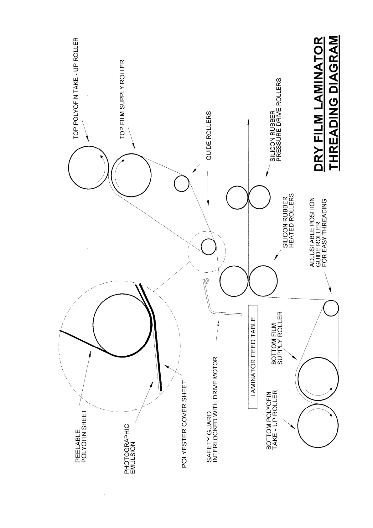
FILM LOADING AND THREADING
WHEN LOADING FILM USE IN CONJUCTION WITH THE FILM THREADING DIAGRAM page 5 or 6
TOP LOADING AND THREADING
1. Remove the feed table and raise the safety guard.
2. Remove the top polyofin take up roller shaft.
3. Remove the top film supply roller shaft.
4. Fit one of the spare cardboard tubes between the two core supports of the top polyofin take up roller shaft.
5. Fit one of the DRY FILM rolls between the two core supports of the top supply roller shaft.
6. Replace the top supply roller shaft with roll of film onto the machine, the round bearing end fits in the
side with the steel spring clip first and the hexagon end fits into the hexagon film tension socket. Ensure
the film roll is loaded the correct way, film dropping off the back of the roll.
7. Replace the top polyofin take up roller shaft.
8. Adjust the lateral position of both dry film roll and cardboard tube to align with each other.
9. Remove the end of the top polyofin film and thread up the top section as per the threading diagram and
stick the edge of the polyofin film to the top take up roller tube with masking tape across the tube width.
10. Roll both rolls together to allow excess film to feed behind the guard and below the centre line of the two
heat rollers.

2
BOTTOM LOADING AND THREADING
1. Remove the bottom polyofin take up roller shaft.
2. Remove the bottom film supply roller shaft.
3. Fit the other spare cardboard tube between the two core supports of the bottom polyofin take up roller
shaft.
4. Fit the second roll of DRY FILM between the two core supports of the bottom supply roller shaft.
5. Replace the bottom supply roller shaft with roll of film onto the machine, the round bearing end fits in the
side with the steel spring clip first and the hexagon end fits into the hexagon film tension socket. Ensure
the film roll is loaded the correct way, film dropping off the front of the roll.
6. Replace the bottom polyofin take up roller shaft.
7. Adjust the lateral position of the bottom DRY FILM roll to align with the top DRY FILM roll, measure if
necessary from the side plate to the side of each roll to ensure accurate alignment. If these rolls are miss-
aligned then a build up of emulsion from the dry film will be come attached to the silicon front heat and
rear pressure rollers causing problems.
8. Adjust the lateral position of the bottom polyofin cardboard
tube to align with the dry film roll.
9. Remove the end of the bottom polyofin film and tread up the
bottom section as per the threading diagram, the bottom guide
idle roller can be easily pulled forward via the curved slots to
allow easy threading ( see diagram ). Stick the edge of the
polyofin film to the bottom take up roller tube with masking
tape across the tube width.
10. Roll both rolls together to allow excess film to feed upwards
above the heat rolls and feed up behind the safety guard and
back over so to remain in position.
11. Lift the pressure release lever on the right side of the laminator
until vertical, this separates the rollers, then feed a scrap piece
of board between the rollers forcing both films through the rollers.
12. Lower the pressure release lever and secure in working
position. See Diagram ( This position is adjustable for
different thickness of panels giving increase roller pressure
the lower the handle ).
13. Lower the safety guard. ( the guard has two switch
interlocks both ends which inhibit the motor rotation )
14. Switch the machine on with the ON/OFF rocker switch at
the rear of the laminator adjacent to the mains input cable
entry, the temperature defaults to zero degrees centigrade,
adjust the motor speed on the front panel to No 4 and switch
the motor on with “ RUN”, allow to feed so that the scrap
card exits fully from the rear of the laminator and then stop
the motor with “ STOP”. If during this operation film jam
problems occur then the “REVERSE” button can be
pressed to eject the film and allow this operation to be
repeated.
15. Re-position the bottom guide roller via the curved slots to the top running position.
16. At this point some tension should be put onto both the film rolls via the two knobs marked “ TENSION “
at the end of the film roll shaft this is to ensure that when the machine is run the film does not snake and
over run when the machine stops. To little tension will cause creasing to much tension will cause the film
to stretch and break, a good starting point is to slacken the tension knob just from the spring and add two
full turns of the tension knob. This is a good starting point, the tension will also need to be adjusted
between different thickness of films and also different manufacturers of films.
17. Run off about 1 metre of film to allow creases and misalignment to be corrected.
18. If both films entry point into the heat rollers are aligned then the laminator is filmed, if not check the
positions of both dry film rolls from the end plates and re-adjust if necessary. Replace the machine table
and align the work feed stop to within 5 mm of the inside edge of the dry film.
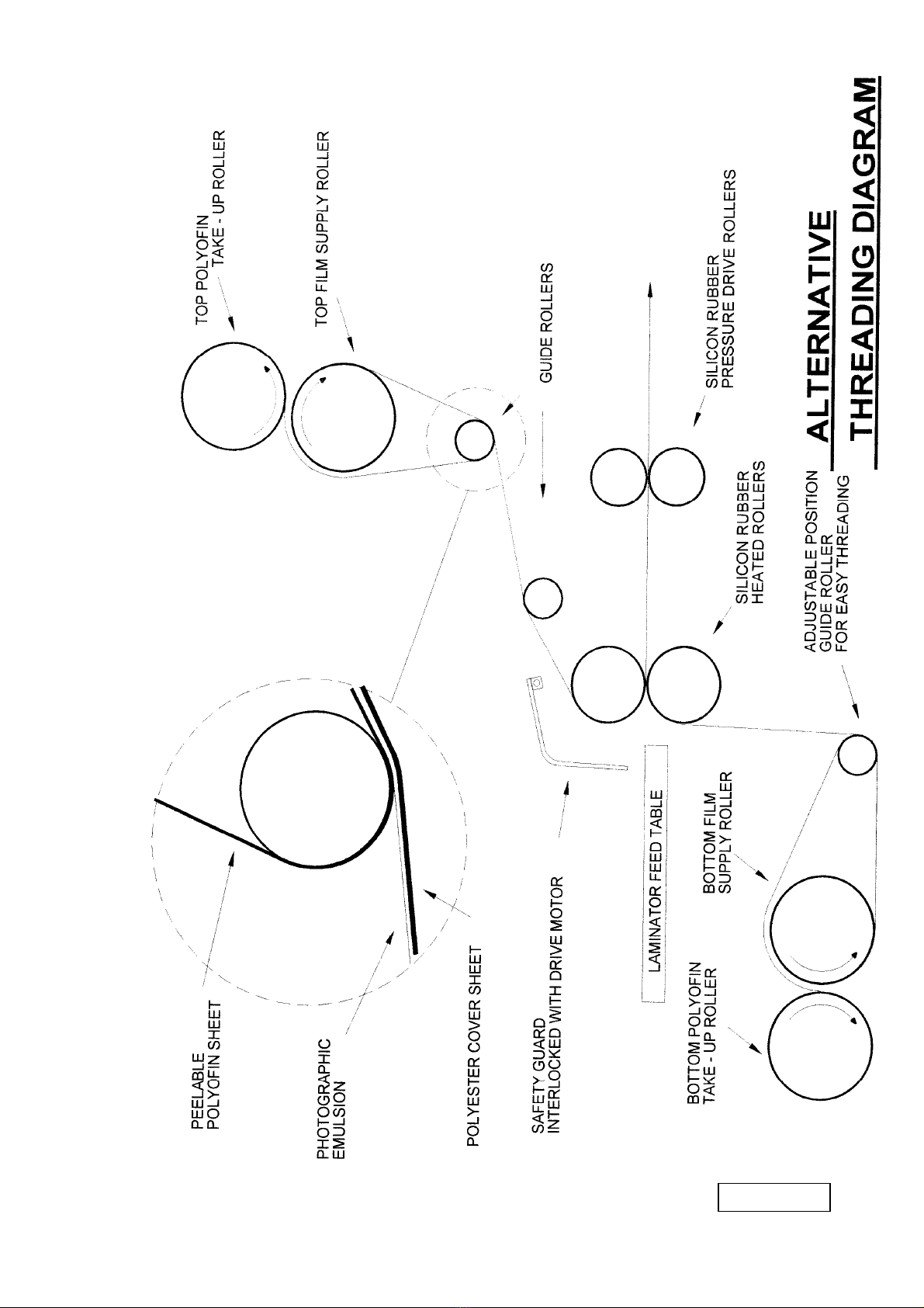
The laminator is now threaded with film and ready to run, it is advisable to check with the manufacturer the
recommended laminating temperature of the dry film, the feed speed and the exit temperature required. As
with some Dry Films the peelable POLYOFIN sheet can have a low melting temperature. The guide roller
adjacent to the machine guard which is situated above the top heat roller can get hot. When the machine is
switched off this POLYOFIN film can stick to the cooling guide roller. When next the machine is switched on
and the drive motor activated this POLYOFIN film can break, if this happens then use the alternative treading
diagram on page 5.

3
MACHINE OPERATION
The machine is very simple to use after threading. Switch the laminator on
with the rear rocker mains switch, the laminator defaults to room
temperature setting, motor off and temperature is reading Centigrade.
Refer to the film temperature and feed rate speed specification from the dry
film data sheet, select one of the four pre-set programs “38” “75” “125”
“250” on the front panel, the temperature setting can be modified by using
the up and down temperature arrowhead keys to select the required
temperature recommended by the Dry Film Manufacturer, similarly using
the up and down arrowhead keys select the required film feed speed.
The laminator now will start to heat up to the set
temperature and this takes about 10 – 12 minutes
dependant on the temperature selected, up to a
maximum high of 130 degrees centigrade. When the
temperature of the heat rollers reach 5 degrees lower
than the selected temperature the “READY” sign will
be displayed on the front panel, and when the
temperature rises 5 degrees above the set temperature
the “READY” sign will flash. This over shoot will
happen on initial warm up and it is best to leave the
laminator a further 3 – 4 minutes to stabilise the
temperature before use. At any time the “MEAS”
button on the front panel can be pressed to display the
actual roller surface temperature of the machine. To
laminate the panels now press “RUN” the motor will
slowly increase speed to the selected speed number and
lamination can commence by feeding the panels against
the side fence on the table and into the pinch grip of the
front rollers. As soon as the first panel has been through
the front heat rollers then introduce the second panel so
as not to waste dry film and continue until all panels
have been laminated, as the panels exit they can be
stacked in a zigzag fashion and separated later with a
sharp knife, the “ STOP” button then switches the
motor off. The “FAN” button is used to switch a
cooling fan on/off, this fan is located between the front
heat rollers and the rear pull rollers below the film line,
it is only operated when the exit temperature of the
laminated panels is above the recommended exit
temperature of the Dry Film manufacturers
specification, usually needed when laminating metal plates which can retain heat longer than printed circuit
boards.
If the machine is left switched on with a high temperature selected and without running for 90 minutes then
the micro-processor will shut the temperature down and remain in a standby mode until required for use, the
digital display will show “st by”, operation of one of the buttons will re-instate the program settings used.
When the laminating of the batch of boards are complete and the machine is not required it is advisable to
move the pressure lever on the right side of the machine upwards to release the pressure on all the rollers at
this point the temperature setting should be reduced to zero degrees on the front panel, the fan button switched
on, speed No 5 selected and switched to run the machine rollers will then rotate without feeding film. Leave
the machine running for approximately 10 – 15 minutes for the rollers to cool down, when the temperature is
below 35 degrees the machine can now be switch off with the rocker switch at the rear of the machine.
After exposure the panels need to be developed in either sodium carbonate or potassium carbonate normally at
a mixture of 10 grams per litre and the solution is used at a temperature of 28 – 30 degrees but remember to
remove the protective polyester cover sheet from the dry film emulsion before developing. Please refer to the
data sheet of the dry film for recommendation as to the temperature and mixture of the developer.

4
PRE – PROGRAM SETTINGS
The Laminator has four pre-programmed settings to cover most of the common films used.
PROGRAM No TEMPERATURE SPEED No SPEED
38 120 degrees Centigrade 8 1.4 Mtr/min
75 115 degrees Centigrade 6 1.0 Mtr/min
125 110 degrees Centigrade 5 0.9 Mtr/min
250 105 degrees Centigrade 3 0.5 Mtr/min
PANEL PREPARATION
Sufficient adhesion, necessary in the subsequent etching and electolytic processes can only be ensured if the
panel material surface is absolutely free of grease and oxides as well as any moisture or traces left by
mechanical/chemical cleaning. This cleaning may be carried out by hand or machine with suitable advice from
the supplier of DRY FILM.
The waiting periods before panel preparation and lamination should not exceed 60 minutes, otherwise there is
a chance that the metal surface may become oxidised and cause loss of adhesion. After laminating, the panels
must be allowed to stand at room temperature for 20 minutes before exposure to ensure the cure of the dry
film emulsion.
STORAGE
The resists of most manufacturers require that the dry films be stored preferably in a dark room at a
temperature of less than 26 degrees centigrade but preferably between 15 – 20 degrees centigrade and at a
relative humidity of 40% - 60 % to ensure full shelf life. Always lay the film box flat never on the end as this
will cause film problems and keep spare or extra rolls of film inside the black plastic bags supplied with the
film and inside the film box in storage.
SPECIFICATION
MAXIMUM WORKING WIDTH MODEL 305 Film width 305 mm (12”) Film Support Tube 330 mm (13”)
MODEL 610 Film width 620 mm ( 24”)Film Support Tube 635 mm (25”)
TEMPERATURE RANGE 0 – 130 degrees CENTIGRADE
LAMINATION SPEEDS 0 – 1.6 metres/minute variable in 10 stages
POWER REQUIREMENTS MODEL 305 220/240 Volts 50/60 Hz
Consumption 1400 watts
Input Current 6 amps
POWER REQUIREMENTS MODEL 610 220/240 Volts 50/60 Hz
Consumption 1800 watts
Input Current 7.8 amps
NET WEIGHT MODEL 305 35 kg
MODEL 610 49 Kg
5
6

7
This manual suits for next models
1
Table of contents


