Fortinet FIM-7901E User manual

FIM-7901E Interface Module Guide
7000

FORTINET DOCUMENTLIBRARY
http://docs.fortinet.com
FORTINETVIDEOGUIDE
http://video.fortinet.com
FORTINETBLOG
https://blog.fortinet.com
CUSTOMERSERVICE&SUPPORT
https://support.fortinet.com
http://cookbook.fortinet.com/how-to-work-with-fortinet-support/
FORTIGATECOOKBOOK
http://cookbook.fortinet.com
FORTINETTRAININGSERVICES
http://www.fortinet.com/training
FORTIGUARDCENTER
http://www.fortiguard.com
FORTICAST
http://forticast.fortinet.com
ENDUSER LICENSE AGREEMENT
http://www.fortinet.com/doc/legal/EULA.pdf
FEEDBACK
Email: techdocs@fortinet.com
Friday, June 23, 2017
FIM-7901E Interface Module Guide
01-540-374567-20170623

TABLEOFCONTENTS
FIM-7901E interface module 4
Physical Description 5
Front panel LEDs 5
Front panel connectors 6
Supported transceivers 7
Turning the module on and off 7
NMI switch 7
FIM-7901E hardware architecture 8
Hardware installation 9
Installing SFP+ and SFP transceivers 9
To install transceivers 9
FIM-7901E mounting components 10
Inserting a FIM-7901E module into a chassis 11
Shutting down and removing a FIM-7901E board from a chassis 16
Troubleshooting 19
FIM-7901E does not startup 19
FIM-7901E status LED is flashing during system operation 19
Quick FIM-7901E configuration 20
Registering your FortiGate-7000 series products 20
Choosing the configuration tool 20
Changing network settings 20
Cautions and Warnings 22
Environmental Specifications 22
Safety 23
Regulatory Notices 25
Federal Communication Commission (FCC) – USA 25
Industry Canada Equipment Standard for Digital Equipment (ICES) – Canada 25
European Conformity (CE) - EU 25
Voluntary Control Council for Interference (VCCI) – Japan 26
Product Safety Electrical Appliance & Material (PSE) – Japan 26
Bureau of Standards Metrology and Inspection (BSMI) – Taiwan 26
China 26
FIM-7901E interface module
FIM-7901E interface module
The FIM-7901E interface module is a hot swappable module that provides data, management and session
sync/heartbeat interfaces, base backplane switching and fabric backplane session-aware load balancing for a
FortiGate-7000 series chassis. The FIM-7901E includes an integrated switch fabric and DP2 processors to load
balance millions of data sessions over the chassis fabric backplane to FPM processor modules.
The FIM-7901E can be installed in any FortiGate-7000 series chassis. Normally you would install two FIM-7901E
modules in chassis hub/switch slots 1 and 2. Two FIM-7901Es provide a total of 32 10GigE small form-factor
pluggable plus (SPF+) interfaces for a FortiGate-7000 chassis.
You can also install FIM-7901Es in a second chassis and operate the chassis in HA mode with another set of
processor modules to provide chassis failover protection.
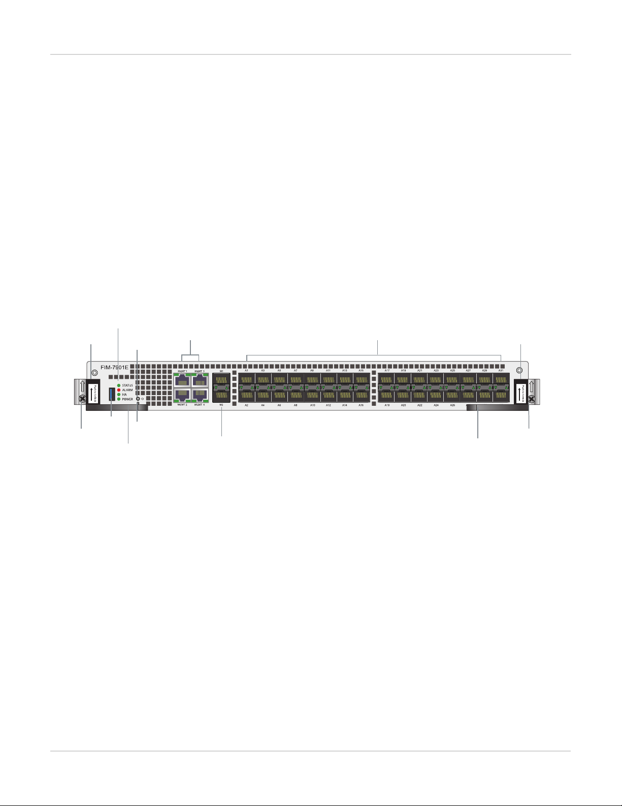
FIM-7901E front panel
Sliding
Latch
Handle
Retention
Screw Handle
Sliding
Latch
Retention
Screw
A1 to A32
10GigE Fabric Channel
SPF+ Network
Interfaces (data)
M1 and M2 10GigE Base
Channel SFP+ Interfaces
(heartbeat and management)
MGMT1 - MGMT4
10/100/1000BASE-T Copper
Management Interface
Status, Alarm
HA and Power
LEDS
USB
Power
Button
NMI
Button
The FIM-7901E includes the following hardware features:
lThirty-two front panel 10GigE SFP+ fabric channel interfaces (A1 to A32). These interfaces are connected to
10Gbps networks to distribute sessions to the FPM processor modules installed in chassis slots 3 and up. These
interfaces can also be configured to operate as Gigabit Ethernet interfaces using SFP transceivers. These
interfaces also support creating link aggregation groups (LAGs) that can include interfaces from both FIM-7901Es.
lTwo front panel 10GigE SFP+ interfaces (M1 and M2) that connect to the base backplane channel. These
interfaces are used for heartbeat, session sync, and management communication between FIM-7901Es in different
chassis. These interfaces can also be configured to operate as Gigabit Ethernet interfaces using SFP transceivers,
but should not normally be changed. If you use switches to connect these interfaces, the switch ports should be
able to accept packets with a maximum frame size of at least 1526. The M1 and M2 interfaces need to be on
different broadcast domains. If M1 and M2 are connected to the same switch, Q-in-Q must be enabled on the
switch.
lFour 10/100/1000BASE-T out of band management Ethernet interfaces (MGMT1 to MGMT4).
lOne 80Gbps fabric backplane channel for traffic distribution with each FPM module installed in the same chassis as
the FIM-7901E.
lOne 1Gbps base backplane channel for base backplane with each FPM module installed in the same chassis as the
FIM-7901E.
4 FIM-7901E Interface Module Guide
Fortinet Technologies Inc.

FIM-7901E interface module Physical Description
lOne 40Gbps fabric backplane channel for fabric backplane communication with the other FIM-7901E in the chassis.
lOne 1Gbps base backplane channel for base backplane communication with the other FIM-7901E in the chassis.
lOn-board DP2 processors and an integrated switch fabric to provide high-capacity session-aware load balancing.
lOne front panel USB port.
lPower button.
lNMIswitch (for troubleshooting as recommended by Fortinet Support).
lMounting hardware.
lLED status indicators.
Physical Description
Dimensions 1.2 x 11.34 x 14 in. (3.1 x 28.8 x 35.1 cm) (Height x Width x Depth)
Weight 7.2 lb. (3.23 kg)
Operating Temperature 32 to 104°F (0 to 40°C)
Storage Temperature -31 to 158°F (-35 to 70°C)
Relative Humidity 10% to 90% (Non-condensing)
Front panel LEDs
From the FIM-7901E font panel you can view the status of the module LEDs to verify that the module is
functioning normally.
LED State Description
STATUS
Off The FIM-7901E is powered off.
Green The FIM-7901E is powered on and operating normally.
Flashing
Green
The FIM-7901E is starting up.
ALARM
Red Major alarm.
Amber Minor alarm
Off No alarms
FIM-7901E Interface Module Guide
Fortinet Technologies Inc.
5
Table of contents
Other Fortinet Recording Equipment manuals


