Fortinet FortiTester 100F User manual

FortiTester 100F
FTS-100F
QuickStart Guide

QuickStart Guide
Register for Support
Register your Fortinet product to receive:
• Technical Support
• New product features
• Protection from new threats
Vous devez enregistrer le produit pour recevoir:
• Support technique
• Nouvelles fonctionnalitées du produit
• Protection contre de nouvelles menaces
La reistrazione ti permette di usufruire di:
• Supporto Tecnico
• Nuove funzionalita
• Proteezione dalle ultime minaccce
Debe registrar el producto para recibir:
• Apoyo técnico
• Nuevas funcionalidades del producto
• Protección contra ataques
登録のお願い
本日、フォーティネット製品の登録をしてください。
登録すると次のメリットがあります。
テクニカルサポート • 新機能の追加 • 新しい脅威への防御
请马上注册
您的飞塔产品
您在注册以后才能得到技术支持、新产品特点信息、最新威胁防护
https://support.fortinet.com
Toll free: 1 866 648 4638
Phone: 1 408 486 7899
Fax: 1 408 235 7737
Email: [email protected]
October 23, 2023
20231023
Copyright© 2020 Fortinet, Inc. All rights reserved. Fortinet®, FortiGate®, FortiCare® and FortiGuard®, and certain other marks are registered trademarks
of Fortinet, Inc., in the U.S. and other jurisdictions, and other Fortinet names herein may also be registered and/or common law trademarks of Fortinet. All
other product or company names may be trademarks of their respective owners. Performance and other metrics contained herein were attained in internal
lab tests under ideal conditions, and actual performance and other results may vary. Network variables, different network environments and other conditions
may affect performance results. Nothing herein represents any binding commitment by Fortinet, and Fortinet disclaims all warranties, whether express or
implied, except to the extent Fortinet enters a binding written contract, signed by Fortinet’s General Counsel, with a purchaser that expressly warrants that
the identified product will perform according to certain expressly-identified performance metrics and, in such event, only the specific performance metrics
expressly identified in such binding written contract shall be binding on Fortinet. For absolute clarity, any such warranty will be limited to performance
in the same ideal conditions as in Fortinet’s internal lab tests. In no event does Fortinet make any commitment related to future deliverables, features or
development, and circumstances may change such that any forward-looking statements herein are not accurate. Fortinet disclaims in full any covenants,
representations, and guarantees pursuant hereto, whether express or implied. Fortinet reserves the right to change, modify, transfer, or otherwise revise this
publication without notice, and the most current version of the publication shall be applicable.
For Product License Agreement / EULA and Warranty Terms, visit https://www.fortinet.com/content/dam/fortinet/assets/legal/EULA.pdf
22 3
44 5
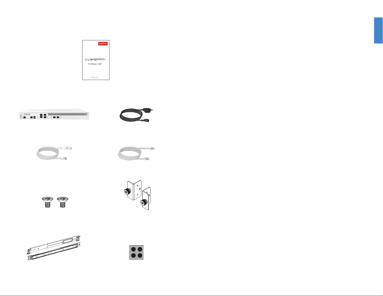
FortiTester 100F
1x Console Cable
(USB to RJ45)
2x M3 Handle Screws
1x Set of Sliding Rails 4x Rubber Feet
1x Set of Handles
1x AC Power Cable
1x Ethernet Cable
QuickStart Guide
Box Includes
66 7
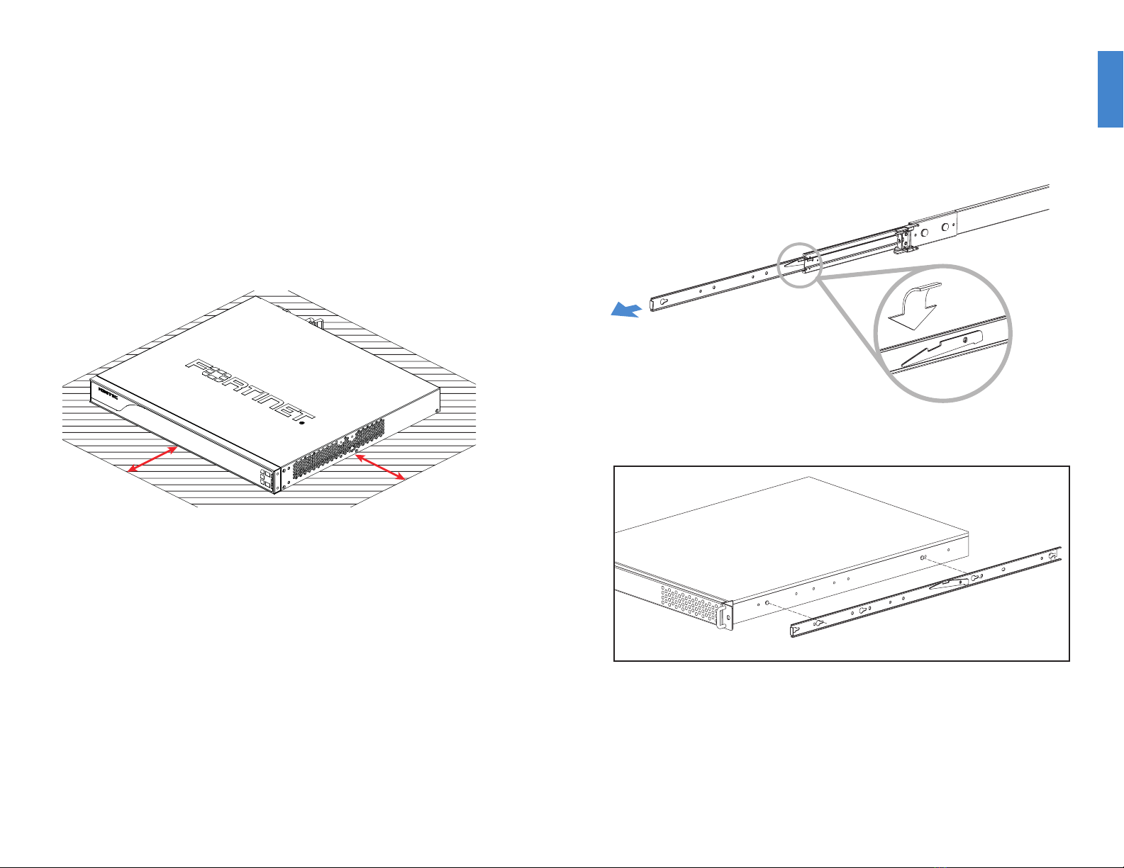
Desktop Installation
Please read “Cautions and Warnings” prior to installing your device.
The appliance can be placed on any flat surface, or mounted in a standard 19 inch rack.
To install the appliance on a at surface
1. Ensure that the surface onto which the appliance to be installed is clean, level, and
stable and that there is at least 1.5in (3.8cm) of clearance on all sides to allow for
adequate airflow.
2. Attach the provided rubber feet to the bottom of the appliance.
3. Place the appliance in the designated location.
4. Verify that the spacing around the appliance conforms to requirements and that the
unit is level.
1.5in
1.5in
To install the FortiTester unit into a rack:
1. Ensure that the FortiTester unit is placed on a stable surface prior to rack-mount
installation.
2. Assemble the rails and install the system in the rack following the safety instructions
and the rack installation instructions in Rail Installation (p.6).
3. Verify that the spacing around the FortiTester unit conforms to requirements and that
the unit is level.
4. Connect the provided power cables to the system.
5. Plug the other end of the power cables into separate power sources, such as
uninterruptible power supplies (UPS) or power distribution units (PDU).
6. Insert one end of the provided Ethernet cable into one of the Ethernet ports on the
FortiTester unit. Insert the other end to a router or switch that is connected to the
internet.
7. Press the power button on the system to turn on the device. Do NOT place heavy
objects on the unit.
To install the FortiTester unit using the rail mount kit:
1. To remove the chassis (inner) member, pull the slide open, and then press the trigger
down as shown on the drawing, and pull the chassis (inner) member out.
2. Use the standoffs to mount the chassis (inner) member to the chassis.
3. To attach the cabinet (outer) member to the rail, first ensure that the safety lock is in
the unlocked position. Then, insert the stag into the upper and lower square holes on
the EIA rail from the back of the rail.
Finally, push the safety lock forward to secure the bracket.
Rail Installation
Pull chassis (inner)
member out
Press the trigger
down to release

88 9
1. To mount the chassis into the cabinet, first ensure that the ball retainer is in the fully
open position. Then, insert the chassis (inner) member into the cabinet member.
When you push the chassis back into the cabinet, press the trigger down to release
the slide from the locked position.
Release safety lock
before mounting
Push the safety lock forward to secure
Retainer is in fully open position
Press trigger down to unlock slides
SFP Ports
To install the SFP transceivers
1. Slide the SFP into the cage socket until it clicks into place
2. Lift latch to lock the SFP
Tx
Rx
Cage Socket
Cage Socket
Latch
SFP
SFP
1
1
2
2
To remove the SFP transceivers
1. Lower the latch to unlock the SFP
2. Carefully pull the SFP out of the cage socket

1010 11
Device Guide
Grounding Screws
Provides extra grounding MGMT
Dedicated Gigabit Ethernet Management Port
for system management.
Reset Button
Reboots the
system.
Console
Optional connection to the
management computer. Provides
access to the CLI.
Power Switch
To turn the power ON/OFF.
Power Connection
100-240V AC, 50-60Hz, 6A-3A.
Ports 1-2
RJ45 type 1 Gigabit Ethernet ports
for connections to your DUT.
Ports 3-4
SFP type 1 Gigabit Ethernet port for
connections to your DUT
Ports 5-6
SFP+ type 10 Gigabit Ethernet port
for connections to your DUT
USB Ports
Reserved for future use

1212 13
Device Guide
Console Port
RJ-45, RS-232 serial. Optional
connection to the management
computer. 9600 bps access to
the CLI.
LED for MGMT, Ports 1-2
Right - Speed
Green: Link established at 1Gps
Amber: Link established at 100Mbps
Off: Link established at 10Mbps or disconnected
Left - LNK/ACT
Green: Link established
Flashing Green: Data activity
Off: No link established
1 - Status
Off: System working normally
Flashing Red: Warning
On: Critical error
4 - Power
Blue: The unit is ON
Off: The unit is OFF
2 - Mode
Off: System is working in node mode
On: System is working as Test Center mode
3 - Hard Drive
Off: Hard drive is not powered
Flashing Amber: Hard drive is acting
1
2
3
4
LED for Ports 5-6
Bottom - Speed
Green: Link established at 10Gbps
Off: Link established at 1Gbps or disconnected
Upper - LNK/ACT
Green: Link established
Flashing Green: Data activity
Off: No link established
LED for Ports 3-4
Green: Link established
Flashing Green: Data activity
Off: No link established
1414
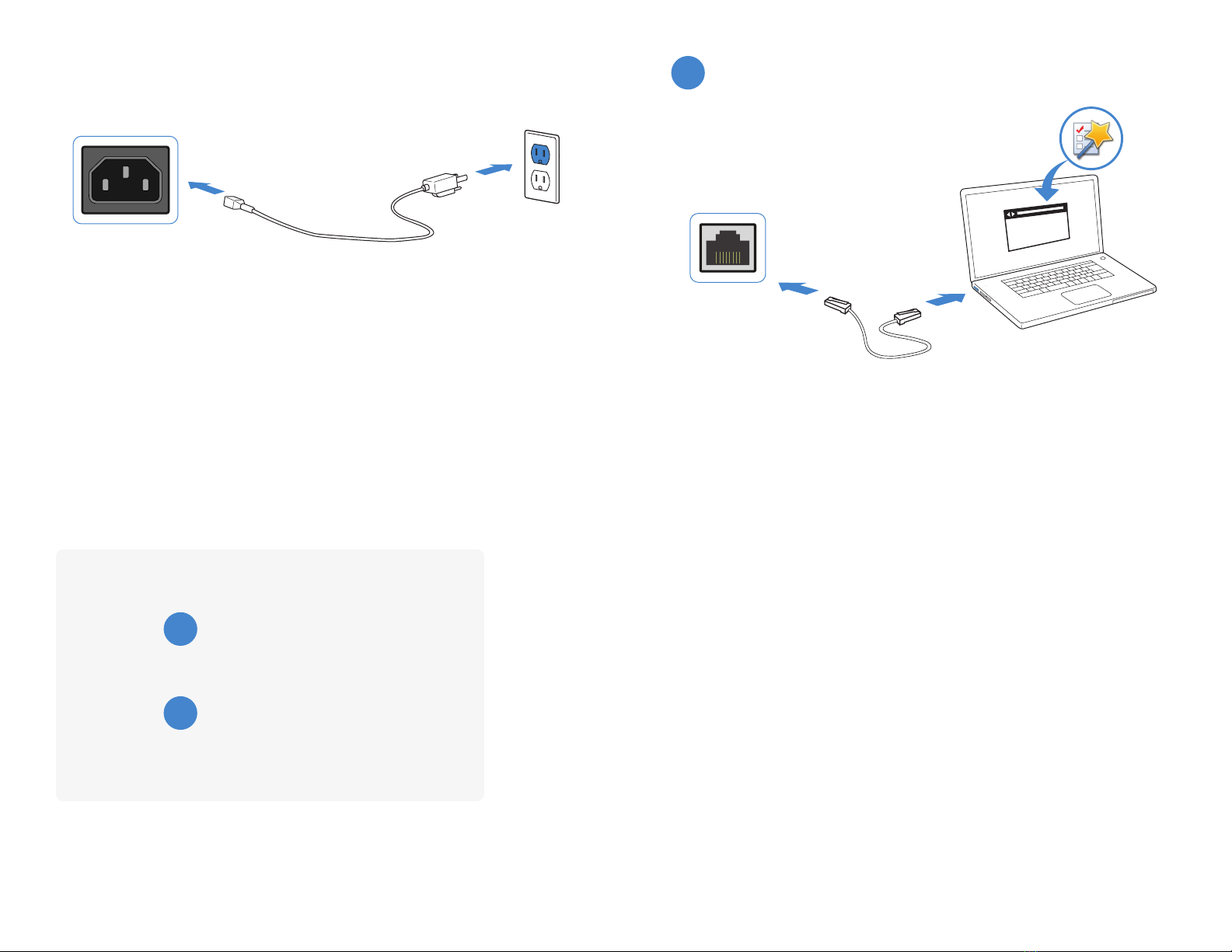
Basic Connections
Plug the provided power cable into the rear of the appliance, and then into a grounded
electrical outlet or a separate power source such as an uninterruptible power supply
(UPS) or a power distribution unit (PDU).
If the appliance has a redundant power supply, connect each power cable to a different
power source.
Power Connection
Setup Options
Web Browser
A
BTerminal Emulation
MGMT Port
http://
Web Browser with Ethernet cable
A
To connect to the web UI
Requires: Microsoft Internet Explorer 9 or higher, the latest version of Mozilla Firefox,
Apple Safari 6, or Google Chrome.
1. Using the Ethernet cable, connect the appliance mangement port to your computer.
2. Configure your computer to match the appliance management port default subnet.
For example, from the Windows 7 Control Panel, go to Network and Sharing Center.
Click the Local Area Connection link, and then click the Properties button. Select
Internet Protocol Version 4 (TCP/IPv4) and then click its Properties button. Select
Use the following IP address, and then enter the following settings:
IP address: 192.168.1.2
Netmask: 255.255.255.0
3. To connect to the web UI, start a web browser and go to http://192.168.1.99.
4. Type admin in the Name field, leave the Password field blank, and then click Login.
15

To connect to the CLI
Requires: Terminal emulator such as PuTTY, Tera Term, or a terminal server.
1. Connect the appliance console port to the management computer using the
provided console cable.
2. Start a terminal emulation program on the management computer, select the
COMport, and use the following settings:
Baud Rate: 9600
Data bits: 8
Parity: None
Stop bits: 1
Flow Control: None
3. Press Enter on your keyboard to connect to the CLI.
4. Login using username admin and no password. You can now proceed with
configuring your device.
Get started by typing ?for a list of available commands.
Begin typing a command then type ?for a list of available ways to complete.
For example config ?shows the lowest level of configuration options.
Terminal Emulation
B
Console Cable
Speed (default): 9600
Data bits: 8
Stop bits: 1
Parity: None
Flow Control: None
Console Port
1616 17

Cautions and Warnings
Environmental specications
Ambient operating temperature: 0°C to 40°C
Rack Mount Instructions - The following or similar rack-mount instructions are included with the installation instructions:
Instructions de montage en rack - Les instructions de montage en rack suivantes ou similaires sont incluses avec les instructions d’installation:
Elevated Operating Ambient - If installed in a closed or multi-unit rack assembly, the operating ambient temperature of the rack environment may be
greater than room ambient. Therefore, consideration should be given to installing the equipment in an environment compatible with the maximum ambient
temperature (Tma) specified by the manufacturer.
Température ambiante élevée – S’il est installé dans un rack fermé ou à unités multiples, la température ambiante de fonctionnement de l’environne-
ment du rack peut être supérieure à la température ambiante de la pièce. Par conséquent, il est important d’installer le matériel dans un environnement
respectant la température ambiante maximale (Tma) stipulée par le fabricant.
Reduced Air Flow - Installation of the equipment in a rack should be such that the amount of air flow required for safe operation of the equipment is not
compromised.
Ventilation réduite – Installation de l’équipement dans un rack doit être telle que la quantité de flux d’air nécessaire au bon fonctionnement de l’équipe-
ment n’est pas compromise.
Mechanical Loading - Mounting of the equipment in the rack should be such that a hazardous condition is not achieved due to uneven mechanical
loading.
Chargement Mécanique – Montage de l’équipement dans le rack doit être telle qu’une situation dangereuse n’est pas lié à un chargement mécanique
inégal.
Circuit Overloading - Consideration should be given to the connection of the equipment to the supply circuit and the effect that overloading of the
circuits might have on overcurrent protection and supply wiring. Appropriate consideration of equipment nameplate ratings should be used when
addressing this concern.
Surtension – Il convient de prendre l’ensemble des précautions nécessaires lors du branchement de l’équipement au circuit d’alimentation et être
particulièrement attentif aux effets de la suralimentation sur le dispositif assurant une protection contre les courts-circuits et le câblage. Ainsi, il est recom-
mandé de tenir compte du numéro d’identification de l’équipement.
Reliable Earthing - Reliable earthing of rack-mounted equipment should be maintained. Particular attention should be given to supply connections other
than direct connections to the branch circuit (e.g. use of power strips).
Fiabilité de la mise à la terre – Fiabilité de la mise à la terre de l’équipement monté en rack doit être maintenue. Une attention particulière devrait être
accordée aux connexions d’alimentation autres que les connexions directes au circuit de dérivation (par exemple de l’utilisation de bandes de puissance).
Refer to specic Product Model Data Sheet for Environmental Specications (Operating Temperature, Storage Temperature, Humidity, and Altitude)
Référez à la Fiche Technique de ce produit pour les caractéristiques environnementales (Température de fonctionnement, température de stockage,
humidité et l’altitude).
Safety
Moving parts — Hazardous moving parts. Keep away from moving fan blades.
Pièces mobiles – Pièces mobiles dangereuses. Se tenir éloigné des lames mobiles du ventilateur.
Battery – Risk of explosion if the battery is replaced by an incorrect type. Do not dispose of batteries in a fire. They may explode. Dispose of used
batteries according to your local regulations. IMPORTANT: Switzerland: Annex 4.10 of SR814.013 applies to batteries.
Batterie – Risque d’explosion si la batterie est remplacée par un type incorrect. Ne jetez pas les batteries au feu. Ils peuvent exploser. Jetez les piles
usagées conformément aux réglementations locales. IMPORTANT: Suisse: l’annexe 4.10 de SR814.013 s’appliquent aux batteries.
警告
本電池如果更換不正確會有爆炸的危險
請依製造商說明書處理用過之電池
Caution: There is a danger of explosion if a battery is incorrect replaced. Replace only with the same or equivalent type.
Dispose batteries of according to the manufacturer’s instructions.
Disposing a battery into fire, a hot oven, mechanically crushing, or cutting it can result in an explosion.
Leaving a battery in an extremely hot environment can result in leakage of flammable liquid, gas, or an explosion.
If a battery is subjected to extremely low air pressure, it may result in leakage of flammable liquid, gas, or an explosion.
Warning:
Lithium-Batterie Achtung: Explosionsgefahr bei fehlerhafter Batteriewechsel. Ersetzen Sie nur den gleichen oder gleichwertigen Typ. Batterien gemäß den
Anweisungen des Herstellers entsorgen.
Beseitigung einer BATTERIE in Feuer oder einen heißen Ofen oder mechanisches Zerkleinern oder Schneiden einer BATTERIE, die zu einer EXPLOSION
führen kann
Verlassen einer BATTERIE in einer extrem hohen Umgebungstemperatur, die zu einer EXPLOSION oder zum Austreten von brennbarer Flüssigkeit oder
Gas führen kann
Eine BATTERIE, die einem extrem niedrigen Luftdruck ausgesetzt ist, der zu einer EXPLOSION oder zum Austreten von brennbarer Flüssigkeit oder Gas
führen kann.
Laser Class 1 optical transceiver shall be used only
L’émetteur-récepteur optique de classe 1 laser doit être utilisé uniquement
Regulatory Notices
Federal Communication Commission (FCC) – USA
This device complies with Part 15 of the FCC Rules. Operation is subject to the following two conditions:
(1) this device may not cause harmful interference, and
(2) this device must accept any interference received; including interference that may cause undesired operation.
This equipment has been tested and found to comply with the limits for a Class A digital device, pursuant to Part 15 of the FCC Rules.
These limits are designed to provide reasonable protection against harmful interference when the equipment is operated in a commercial
environment. This equipment generates, uses, and can radiate radio frequency energy, and if it is not installed and used in accordance
with the instruction manual, it may cause harmful interference to radio communications. Operation of this equipment in a residential area
is likely to cause harmful interference, in which case the user will be required to correct the interference at his own expense.
WARNING: Any changes or modications to this product not expressly approved by the party responsible for compliance could void the
user’s authority to operate the equipment
Industry Canada Equipment Standard for Digital Equipment (ICES) – Canada
CAN ICES-003 (A) / NMB-003 (A)
This digital apparatus does not exceed the Class A limits for radio noise emissions from digital apparatus set out in the Radio
Interference Regulations of the Canadian Department of Communications.
Cet appareil numérique n’émet pas de bruits radioélectriques dépassant les limites applicables aux appareils numériques de la classe A
prescrites dans le Règlement sur le brouillage radioélectrique édicte par le ministère des Communications du Canada.
European Conformity (CE) - EU
This is a Class A product. In a domestic environment, this product may cause radio interference, in which case the user may be required
to take adequate measures.
Voluntary Control Council for Interference (VCCI) – Japan
この装置は、クラスA情報技術装置です。 この装置を 家庭環境で使用すると電波妨害を引き起こすことがあります。 この場合には使用
者が適切な対策を講ずるよう要求されることがあります。VCCI-A
Product Safety Electrical Appliance & Material (PSE) – Japan
日本では電気用品安全法(PSE)の規定により、同梱している電源コードは本製品の専用電源コードとして利用し、他の製品に使用しな
いでください。
Bureau of Standards Metrology and Inspection (BSMI) – Taiwan
The presence conditions of the restricted substance (BSMI RoHS table) are available at the link below:
限用物質含有情況表 (RoHS Table) 請到以下 網址下載:
https://www.fortinet.com/bsmi
此為甲類資訊技術設備,於居住環境中使用時,可能會造成射頻擾動,在此種情況下,使用者會被要求採取某些適當的對策。
英屬蓋曼群島商防特網股份有限公司台灣分公司
地址:台北市內湖區行愛路176號2樓
電話:(02) 27961666
China
此为A级产品,在生活环境中,该产品可能会造成无线电干扰。这种情况下,可能需要用户对其采取切实可行的措施。
1818 19

This manual suits for next models
1
Table of contents
Other Fortinet Test Equipment manuals


