AFL ROGUE cB1 User manual

www.AFLglobal.com, +1 (800) 321-5298 or +1 (603) 528-7780
Test & Inspection
ROGUE Device
User’s Guide
Test Workflow and Data Management Solution

2
Table of Contents
Safety Information............................................ 3
aeRos®| Rogue®Solution Overview .............................. 4
aeRos — Test Workflow and Data Management Solution .................4
ROGUE — Modular Platform ......................................4
ROGUE®cB1 Overview ......................................... 5
Contents of ROGUE cB1 Kit........................................5
Recommended Accessories ........................................5
Hardware Overview..............................................6
Controls, Display, Interfaces ......................................6
Battery Charging................................................7
Checking the Battery Status ......................................7
Installing a Module ..............................................8
Touch Screen Display Features......................................9
Turning On/Off VFL Port (if present) .................................10
ROGUE®iB1 Overview ......................................... 11
Contents of ROGUE iB1 Kit ........................................11
Recommended Accessories ........................................11
Hardware Overview..............................................12
Controls, Display, Interfaces ......................................12
Battery Charging and Operation ....................................13
Checking the Battery Status ......................................13
Installing a Module ..............................................14
Turning On/Off VFL Port (if present) .................................14
Touch Screen Display Features......................................15
Device Settings Overview .........................................17
Wi-Fi .......................................................18
Bluetooth ....................................................18
Display ......................................................19
Sound & Notification ...........................................20
Apps........................................................20
Memory .....................................................21
Add Account..................................................21
General ..................................................... 22
Recommended Accessories ..........................................22
Cleaning Tips ....................................................22
Cleaning Connectors on Test Cables and Fiber Under Test .................22
Cleaning the Optical Ports.........................................22
Recharging Batteries ...............................................24
Repair and Calibration..............................................24
General Information ...............................................25
Standards Compliance Information ..................................25
Contacting Customer Service.......................................25
Warranty Terms and Conditions.....................................25
©2017, AFL, all rights reserved. RG-UG-1000 Revision Ab 2017-04-17
Specications are subject to change without notice.

3
Safety Information
WARNING! Use of procedures or adjustments other than those specied herein may result in
hazardous radiation exposure.
NOTE! ROGUE testers contain Bluetooth / WiFi Transceiver
FCC ID: TFB-TIWI1-01
IC ID: 5969A-TIWI101
CAUTION! To avoid serious eye injury, never look directly into the optical outputs of ber optic
network equipment, test equipment, patch cords, or test jumpers. Refer to your company’s safety
procedures when working with optical systems.
WARNING! Use only the specied AC adapter. Use of another type of AC adapter can damage
the instrument and create the danger of re and electrical shock.
AC adapter should be 90-240VAC input, 15Vdc @ 2.4A, with center positive connector
WARNING! To avoid the danger of re and electrical shock:
• Never use a voltage that is different from that for which the AC adapter is rated.
• Do not plug the device into a power outlet that is shared by other devices.
• Never modify the power cord or excessively bend, twist, or pull it.
• Do not allow the power cord to become damaged. Do not place heavy objects on the power
cord or expose it to heat.
• Never touch the AC adapter while your hands are wet.
• Should the power cord become seriously damaged (internal wiring exposed or shorted),
contact the manufacturer to request servicing.
CAUTION! Do not run any tests or perform functions that activate an LED/LASER output port
unless ber cable is attached to the corresponding output port.
NOTICE! ROGUE Testers contain no user serviceable parts. Except for changing batteries and
cleaning optical ports, this instrument must be returned to AFL or authorized agents for repair and
calibration.
IMPORTANT! Proper care in handling should be taken when using any precision optical test
equipment. Scratched or contaminated optical connectors can impact the performance of the
instrument.
IMPORTANT! It is important to keep connector end-faces on the launch and receive cables and
those on the Fiber Under Test (FUT) clean, to ensure accurate measurements and operation.

4
aeRos®| Rogue®Solution Overview
AFL's ROGUE™| aeRos™Test Workow and Data Management Solution is a suite of products built
completely around your company’s specic testing requirements.
aeRos — Test Workflow and Data Management Solution
ROGUE — Modular Platform
aeRos is an open, cloud-based, workow management platform that facilitates two-way
communication and data exchange from engineering to project management to technicians in
the eld. aeRos allows project managers to send jobs directly to technicians, dening tests and
congurations as needed. This reduces both setup time and mistakes in the eld creating real
OPEX savings. Throughout the job, managers can monitor technicians' progress and help to solve
problems as they arise avoiding expensive retesting and unnecessary truck rolls. aeRos solution is
available in two options: aeRos BASIC and aeRos PRO:
aeRos BASIC — Data Management Solution
aeRos BASIC allows users to save their test data in the aeRos cloud and then retrieve it from
anywhere at any time with a standard Internet browser such as Chrome or Safari. aeRos BASIC is
free to all owners of AFL’s ROGUE modular test equipment.
aeRos PRO — Workflow Management Solution
aeRos PRO allows users to manage their entire testing workow and enables seamless and
efcient communications and data management. aeRos PRO is available in multiple License
congurations.
ROGUE is the modular hardware platform that works seamlessly with aeRos. Like aeRos, it is an
open system built around you, for both CAPEX and OPEX savings. By unbundling software and
hardware, the ROGUE platform allows you to invest in the application-specic tests you really
need. Because ROGUE works with iOS or Android, you can leverage your investment in your
existing smart devices. Your technicians will use equipment and capabilities they are familiar with,
further increasing their overall efciency and your OPEX savings. The ROGUE platform is available
in two modications: ROGUE cB1 Compact Base or ROGUE iB1 Intelligent Base.
The ROGUE cB1 compact base is ruggedly built to withstand testing in the eld. It is
lightweight, portable, and comes with options for carrying and/or placing it on a surface, with a
convenient carrying strap and a “kick-stand”. The ROGUE cB1 works with most Android tablets
and phones.
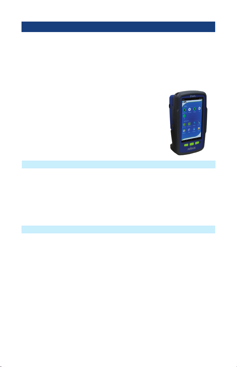
The ROGUE iB1 intelligent base is the latest addition to the ROGUE modular family of test
equipment. The ROGUE iB1 is hand-held, portable, and comes with a unique kickstand design
that allows for portrait or landscape viewing. The iB1 intelligent base utilizes an Android inspired,
icon-based user interface and provides superior ease of use through a large, 7” high resolution
color touchscreen display making for an ideal solution for applications where smart devices are
prohibited or undesired.
Both ROGUE devices share test modules and application software such as the TURBO OLTS/Cert
test and LinkMap OTDR test apps.

5
ROGUE®cB1 Overview
Contents of ROGUE cB1 Kit
Recommended Accessories
The Rogue cB1 is designed to mate with one of various test Modules. A test Module mounts in
and interfaces with the cB1, with the cB1 providing control/data interfacing and power to the test
Module. The Rogue cB1 is ruggedly built to withstand testing in the eld. It is lightweight, portable,
and comes with options for carrying and/or placing it on a surface, with a convenient carrying strap
and a “kickstand”.
ROGUE cB1 Key Features
• WiFi/Bluetooth Connectivity
• Touch Screen
• "Mini-Apps" - Pairing, Power Manager, Module Information
• USB Connections
• Power Connections/Removable Battery
• Ergonomics - stands on its own, Kickstand, Anchor Points/Strap
Depending on your testing requirements, AFL recommends the following accessories:
• ROGUE cB1 Kickstand
• AC Adapter
• Adapters (LC, SC)
• Multi-ber Switch: enables the testing of 12 ber cables without the need to use a breakout
cable. Multi-ber Switch is also available in Certication Add-on kits.
• FOCIS Flex Fiber Optic Connector Inspection System
• AFL's cleaning supplies
• AFL's Fiber Rings
• SM, MM Reference Jumper Cables
• MPO reference Jumper Cables
Each ROGUE cB1 kit includes one of each:
• ROGUE cB1
• Battery
• Power supply
• Adjustable carry strap
6
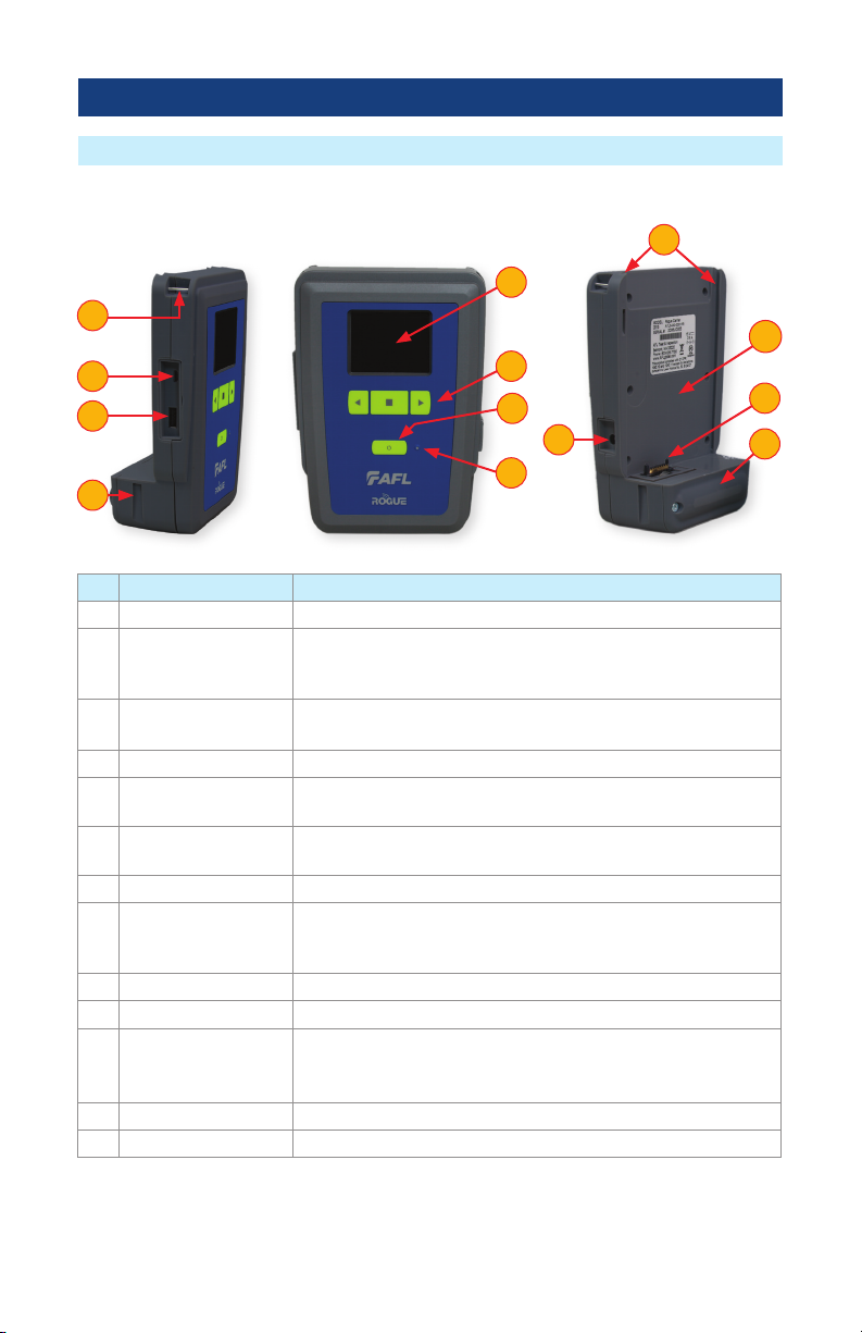
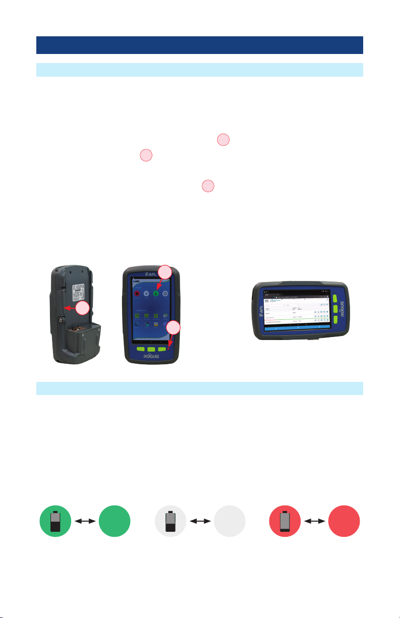
ROGUE®cB1 Overview
Hardware Overview
Ref Feature Description
1 Strap Eyelet Used to attach an adjustable carry strap supplied with your cB1.
2 Mini-USB Function
Port
This port may be used to connect the cB1 to a PC for downloading
and managing test data, updating User Interface software or for
remote control of the device.
3 USB Host Port This USB port allows connection to USB devices (keyboard, USB
ash drive, or other USB devices)
4Key Slot Used to mount a Kickstand accessory on the ROGUE cB1.
5 Touch Screen Display Contains on-screen controls and menus, allowing the user to select
parameters and functions and control the operation of the cB1.
6 Function Buttons Used to perform specic tasks. The functionality of these buttons
depends on the active test mode/screen.
7 Power Button Press and hold (~2 seconds) to turn power on or off.
8 AC/Charger Indicator When ON, indicates that an AC adapter is connected to the cB1.
-Red light - rechargeable battery is charging.
-Green light - rechargeable battery is fully charged.
9Guide Rails Used to mount a Module on the ROGUE cB1.
10 Slot for Module This slot accepts one of the ROGUE Modules.
11 Module Interface
Connector
This connector interfaces with a test module, providing power
and passing control and data signals between the cB1 and
module.
12 Battery Compartment Holds removable/rechargeable Li-ion battery.
13 AC/Charger Port This is the connector for the AC power adapter/charger.
Controls, Display, Interfaces
37
2
13
11
12
8
4
6
10
5
1
9

7
Checking the Battery Status
Battery Charging
The battery icon on the ROGUE cB1 device display indicates the battery status and shows
percentage of the remaining battery charge.
Battery/Power Level
icon
will indicate current charge level as follows:
– Green = >50%
– White = Between 20% and 50%
– Red = <20%
Rogue cB1 device can simultaneously operate and charge the internal battery while connected to
the provided AC adapter. To connect the AC adapter:
• Plug the AC adapter/charger into a standard wall outlet.
• Connect the AC adapter/charger to the power port located on the Rogue side panel
A
.
– The AC/Charger indicator
B
turns RED while battery is charging.
– The AC/Charger indicator turns GREEN when battery is fully charged.
A
ROGUE cB1 Overview
50% 30% 20%
B

8
Installing a Module
1. Starting from the cB1 top, align bottom of the Module guiding tracks
A
with top of the cB1
guiding tracks
B
.
2. Slide the Module into the cB1 base.
3. Make sure that Module is completely inserted in the Module Slot.
4. To secure Module, depress the two latch pins until fully seated
C
.
5. Align Kickstand guiding tracks
D
with the cB1 base key slots
E
.
6. Slide the cB1 with mounted Module into Kickstand until fully seated.
7. For stationary use, ip-out the Kickstand handle
F
and position the assembled ROGUE
tester vertically on a at surface.
1
2
3
4
5
6
7
2 3
1
A
B
6
4
C
5
E
D
7
F
ROGUE cB1 Overview

9
Touch Screen Display Features
ROGUE cB1 Overview
Ref Icon Function
1Bluetooth Connectivity.
Pressing this icon will display the Bluetooth pairing screen.
• If your ROGUE device is not already paired, the Bluetooth connectivity screen
will display a QR code that can be used to pair with a Smart Device. See
"Bluetooth Pairing – Connecting to a ROGUE™ Device" on page 14 .
• If your ROGUE device is already paired, the Bluetooth pairing screen will
display an option to disconnect.
Color code will indicate pairing status as follows:
Red = Bluetooth off
Red Pulsating = Paired with Smart Device; waiting for connection to App.
Green = Paired with Smart Device and TURBO™App is running
2Module Info
Color code:
• Red = Module is not installed (or not completely installed); tapping the icon
will result in an error message “No Module”
• Green = Module is properly installed and seated; tapping the icon will provide
information on the serial number and description of the installed module.
3Battery/Power Level.
This icon will indicate current charge level.
Color code:
Green = >50%
White = Between 20% and 50%
Red = <20%
4cB1 Information
Pressing this icon provides options to display the following information:
Module Version (if a Module installed), cB1 Version, Legal Information.
5VFL port.
Present only when the installed module has a VFL port.
Color code:
White = VFL port is Off
Green = VFL port is On
Flashing Green = VFL is On/Pulse.
1
4 5
3
2
10
ROGUE cB1 Overview
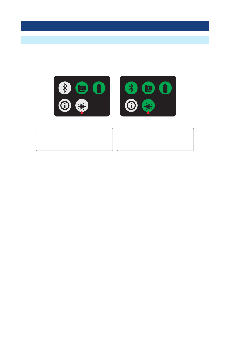
Turning On/Off VFL Port (if present)
The VFL icon on the cB1 touch screen display is the VFL port on/off button. To enable/disable the
VFL port, touch the VFL icon.
VFL port icon
WHITE indicates that laser is disabled
Tap to enable the VFL port
VFL port icon
GREEN indicates that laser is enabled
Tap to disable the VFL port
11
ROGUE®iB1 Overview
Contents of ROGUE iB1 Kit
Recommended Accessories
ROGUE iB1 Key Features
• WiFi/Bluetooth Connectivity
• Touch Screen
• USB Connections
• Power Connections/Removable Battery
• Ergonomics - stands on its own, Kickstand, Anchor Points/Strap
Depending on your testing requirements, AFL recommends the following accessories:
• AC Adapter
• Adapters (LC, SC)
• Multi-ber Switch: enables the testing of 12 ber cables without the need to use a breakout
cable. Multi-ber Switch is also available in Certication Add-on kits.
• FOCIS Flex Fiber Optic Connector Inspection System
• AFL's cleaning supplies
• AFL's Fiber Rings
• SM, MM Reference Jumper Cables
• MPO reference Jumper Cables
Each ROGUE iB1 kit includes one of each:
• ROGUE iB1
• Battery
• Power supply
• Adjustable carry strap
The Rogue iB1 is designed to mate with one of various test Modules. A test Module mounts in
and interfaces with the iB1 providing control/data interfacing and power to the test Module. The
ROGUE iB1 is hand-held, portable, and comes with a unique kickstand design that allows for
portrait or landscape viewing. The iB1 intelligent base utilizes an Android inspired, icon-based user
interface and provides superior ease of use through a large, 7” high resolution color touchscreen
display making for an ideal solution for applications where smart devices are prohibited or
undesired.
12
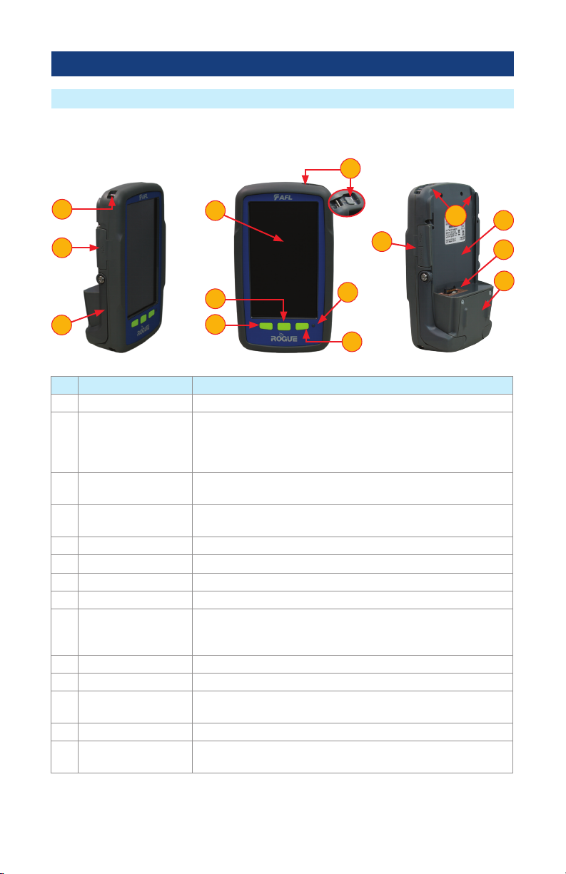
ROGUE®iB1 Overview
Hardware Overview
Ref Feature Description
1 Strap Eyelet Used to attach an adjustable carry strap supplied with your cB1.
2 USB Ports
Compartment
Contains the following ports:
Mini-USB Function Port, which may be used for remote control of
the device
USB Host Port, which allows connection to USB devices
3 Kickstand Kickstand accessory mounted on the ROGUE iB1. Used for portrait
or landscape positioning.
4 Touch Screen Display Contains on-screen controls and menus; allows to select
parameters/functions and control the operation of the iB1.
5 Home Button Press to display Home Scree
6 Back Button Press to return to the previous screen
7 Window Button Allows the user to open, switch or close Apps that are running
8 Power Button Press and hold (~2 seconds) to turn power on or off.
9 AC/Charger Indicator When ON, indicates that an AC adapter is connected to the
ROGUE cB1 device: Red light - rechargeable battery is charging;
Green light - rechargeable battery is fully charged.
10 Guide Rails Used to mount a Module on the ROGUE iB1.
11 Slot for Module This slot accepts one of the ROGUE Modules.
12 Module Interface
Connector
This connector interfaces with a test module providing power and
passing control and data signals between the iB1 and module.
13 Battery Compartment Holds removable/rechargeable Li-ion battery.
14 USB/AC Ports
Compartment
Contains USB Host Port (connection to USB devices) and AC/
Charger Port (interface for AC power adapter/charger).
Controls, Display, Interfaces
9
4
14 12
13
11
10
8
5
7
6
3
1
2
13
ROGUE iB1 device can simultaneously operate and charge the internal battery while connected to
the provided AC adapter/charger. To connect the AC adapter/charger:
• Plug the AC adapter/charger into a standard wall outlet.
• Connect the AC adapter/charger to the power port
A
.
– The AC/Charger indicator
B
turns RED while battery is charging.
– The AC/Charger indicator turns GREEN when battery is fully charged.
The battery icon on the ROGUE iB1 device display
C
indicates the battery status and shows
percentage of the remaining battery charge as follows:
– Green = >50%,
– White = 20% - 50%,
– Red = <20%
Battery Charging and Operation
iB1 may be used in either vertical
or horizontal orientation
ROGUE®iB1 Overview
Checking the Battery Status
The battery icon on the ROGUE iB1 device display indicates the battery status and shows
percentage of the remaining battery charge.
Battery/Power Level
icon
will indicate current charge level as follows:
– Green = >50%
– White = Between 20% and 50%
– Red = <20%
50% 30% 20%
A
B
C

14
ROGUE®iB1 Overview
1. Starting from the iB1 top, align bottom of the Module guiding tracks
A
with top of the iB1
guiding tracks
B
.
2. Slide the Module into the iB1 base.
3. Make sure that Module is completely inserted in the Module Slot.
4. To secure Module, depress the two latch pins until fully seated
C
.
5. For stationary operation, use Kickstand handles to position the assembled ROGUE tester on a
at surface. You can choose either portrait (vertical) or landscape (horizontal) orientation:
– Flip-out one handle for horizontal positioning
D
– Flip-out two handles are used for vertical positioning
E
1
2
3
4
5
Installing a Module
2 3
1
A
B
4
C
5
D
E
Turning On/Off VFL Port (if present)
The VFL icon on the iB1 touch screen display is the VFL port on/off button. To enable/disable the
VFL port, touch the VFL icon.
VFL port icon
WHITE indicates that laser is disabled
Tap to enable the VFL port
VFL port icon
GREEN indicates that laser is enabled
Tap to disable the VFL port
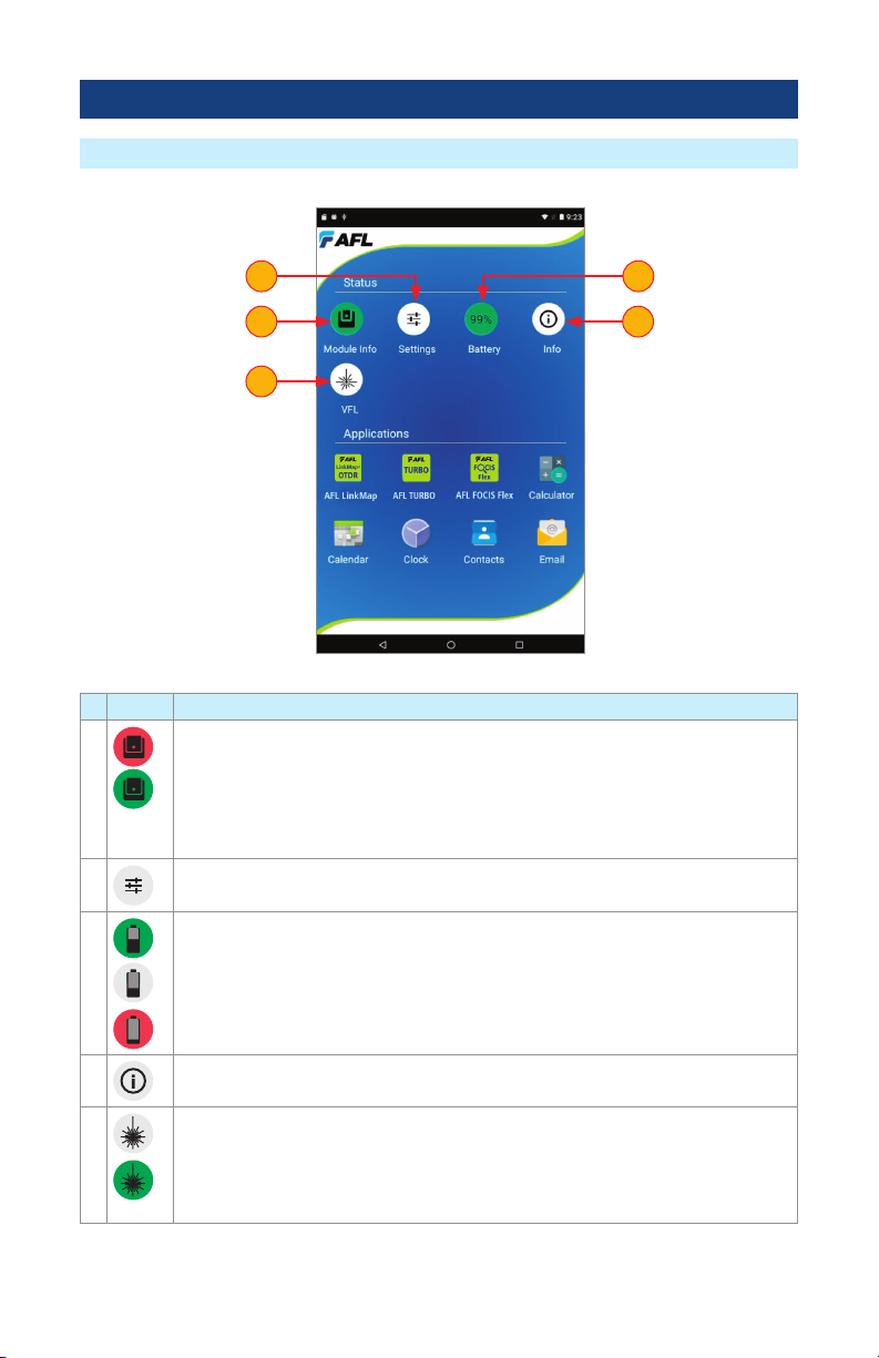
15
Touch Screen Display Features
# Icon Function
1Module Info
Color code:
• Red = Module is not installed (or not completely installed); tapping the icon will
result in an error message “No Module”
• Green = Module is properly installed and seated; tapping the icon will provide
information on the serial number and description of the installed module.
2Settings - Used to set Wi-Fi, Bluetooth, Sound, Notications and other common
system features.
3Battery/Power Level - This icon will indicate current charge level.
Color code:
Green = >50%
White = Between 20% and 50%
Red = <20%
4ROGUE iB1 Information - Pressing this icon provides options to display the
following information: Module Version (if installed), iB1 Version, Legal Information.
5VFL port - Only present if the installed Module has a VFL port.
Color code:
White = VFL port is Off.
Green = VFL port is On.
Flashing Green = VFL is On/Pulse.
1
5
4
2 3
ROGUE®iB1 Overview

16
Touch Screen Display Features
6
7
A
ROGUE®iB1 Overview
# Icon Function
6 OnBoard AFL developed Apps - Tap an App icon to launch.
7 Factory set App tools - Tap any of the factory set App tools to launch.
8Active Tray
Upon installation of a module, the iB1 senses what module type is present and
launches the appropriate Mobile App
This App appears in the active “Tray”
A
at the bottom of the home screen.
8

17
Device Settings Overview
ROGUE®iB1 Overview
A
Device Settings screen is accessed from the Home screen by tapping the settings icon
A
Wireless and networks settings
•
Wi-Fi
•
Bluetooth
iB1 device general settings
•
Home
•
Display
•
Sounds & Notication
•
Apps
•
Battery
•
Memory
Personal settings:
•
Accounts
•
Language & Input
System settings:
•
Date & Time
•
Accessibility
•
About Device

18
Device Settings Overview
Wi-Fi
• When in the Settings Screen, tap the Wi-Fi option
A
• From the displayed list, choose the desired network
B
• In the displayed Password eld, enter password
C
• Tap Connect
D
.
Bluetooth
• When in the Settings Screen, tap the Bluetooth option
E
.
• Once the Bluetooth screen is displayed, tap Bluetooth On/Off control to turn it On
F
.
• From the displayed list of nearby Bluetooth devices, select the desired device
G
.
• Tap Pair
H
.
• When pairing is successful, tap OK.
D
H
F
A
E
B
G
C
ROGUE®iB1 Overview

19
Device Settings Overview
Display
Tapping the Display option
A
allows the user to choose settings for Brightness Level, Sleep mode,
and Font Size as follows.
• Brightness Level:
– Tap on the Brightness Level option
B
as needed.
– When the Brightness adjusting slider is displayed, set it to the desired Brightness level.
• Sleep:
– Tap on the Sleep option to display a sub-menu
– Select the desired time of inactivity before iB1 device will go to sleep mode
C
.
• Font Size:
– Tap on the Font Size option to display a sub-menu
– Select the desired Font Size
D
.
A
ROGUE®iB1 Overview
B
B
C
D
20
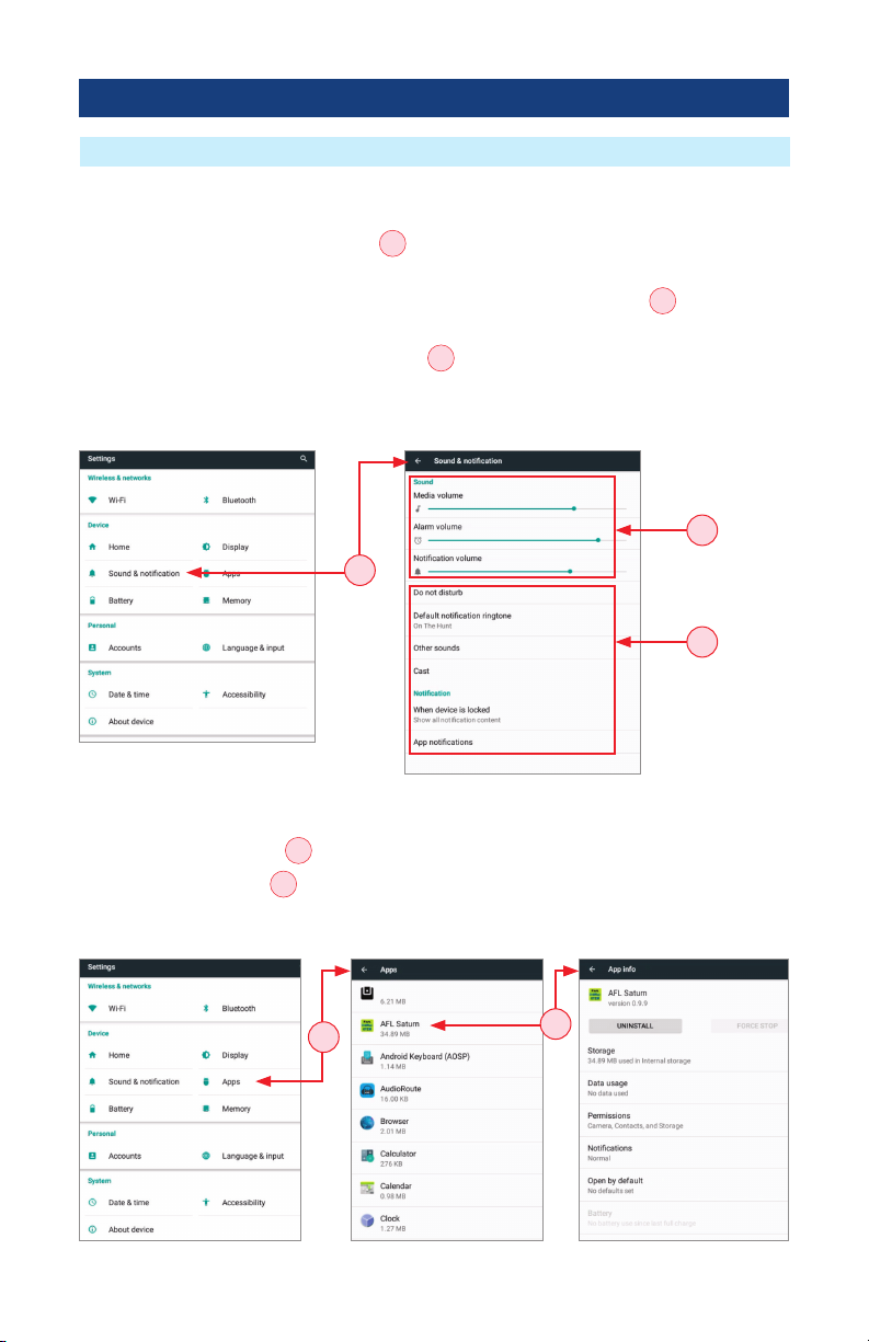
Device Settings Overview
Sound & Notification
Tapping the Sound & Notications option
A
will display settings screen that allows the user to
set various sound and notication parameters as follows.
• For Volume Settings (Media, Alarm, Notication), use the adjustment sliders
B
to set the
desired volume level.
• For all other Sound and Notication Settings
C
(Do not disturb, Default notication ringtone,
Other sounds, Casting, Notications when device is locked,Notication for individual Apps), tap
the desired option to display a sub-screen, and then select the desired option.
ROGUE®iB1 Overview
B
C
Apps
• Tapping the Apps option
D
provides a list of resident Apps on the iB1 and their sizes in MB.
• Tapping a specic App
E
will provide the user with more detailed information and settings
options.
A
DE
Other manuals for ROGUE cB1
1
This manual suits for next models
3
Table of contents
Other AFL Test Equipment manuals


