Fortress Building Products FortressAccents User manual

1
FORTRESSACCENTS INSTALLATION: PLUG AND PLAY
FORTRESSACCENTS PLUG AND PLAY
INSTALLATION INSTRUCTIONS

2
FORTRESSACCENTS INSTALLATION: PLUG AND PLAY
Introducon.........................................................................3
RequiredTools/LighngOpons..............................4
LighngComponents..............................................5
Installaon
ProjectPlanning.......................................................6
WireSetup...............................................................8
Metal Post
FlatPyramidCap.........................................12
LEDCapLight..............................................13
LEDGlowRing............................................16
LEDVercalPostLight................................18
LEDSurfaceMountLight............................20
Wood Post
FlatPyramidCap........................................22
LEDLighng................................................24
PostBaseCover.......................................................25
Screw-less PostBaseCover.....................................26
TuyaSmartAppforSmartController......................27
Care&Maintenance/Warranty..........................................31
AboutCaliforniaProposion65:
hps://fortressbp.com/about/californiaproposion65
TABLE OF CONTENTS

3
FORTRESSACCENTS INSTALLATION: PLUG AND PLAY
INTRODUCTION
READ INSTRUCTIONS COMPLETELY BEFORE
STARTING INSTALLATION
Itistheresponsibilityoftheinstallertomeetallcodeand
safetyrequirements,andtoobtainallrequiredbuilding
permits.Thedeckandrailinginstallershoulddetermine
andimplementappropriateinstallaontechniquesforeach
installaonsituaon.FortressBuildingProductsandits
distributorsshallnotbeheldliableforimproperorunsafe
installaons.
WARNING–RiskofElectricShock.Installpowerunit10’
[3048mm]ormorefromapool,spa,orfountain.Wherethe
powerunitisinstalledoutdoors,connectpowerunittoa
receptacleprotectedbyaGFCI.
AFortressAccentsTransformershouldalwaysbeusedto
operateFortressAccentsLEDlighng.FortressAccents
TransformersareavailablewhereverFortressAccentsLED
lighngissold.
UseofatransformerthatisnotaFortressAccentstransformer
withFortressAccentsLEDLighngwillvoidthewarranty.
• READ INSTALLATION INSTRUCTIONS BEFORE WIRING.
• NOT FOR USE WITH DIMMERS.
• FOR OUTDOOR USE ONLY. MOUNT AT LEAST 12” [305mm]
ABOVE GROUND.
• NOT FOR USE WITH SUBMERSIBLE FIXTURES.
• DO NOT CONNECT TWO OR MORE TRANSFORMERS IN
PARALLEL.

4
FORTRESSACCENTS INSTALLATION: PLUG AND PLAY
Required Materials
Goggles Tape
Measure
PhillipsHead
Screwdriver
Drill
T-25
DriverBit
DrillBits:
1/16”[2mm],1/8”[3mm],
5/32”[4mm],1/2”[13mm]
Pencil
ForstnerBit:
1”[25mm]
Rubber
Mallet
Light Opon
LEDCapLight
Fish
Tape
Cable
Clip
Light Projecon
LED Glow Ring
Recommended Install Posion
The LED Glow Ring is
recommendedtobeinstalled
betweenthePostCapandPost
CapBase.
TheLEDCapLightis
recommendedtobeinstalled
face down inside the slot holes
inthePostCapBase.
TheLEDVercalPostLightis
recommendedtobeinstalled
ontovercalsurfaces.
The LED Surface Mount Light is
recommendedtobeinstalled
onthedecksurface,sots,or
stairrisers.
Lighng
LEDVercal
Post Light
LED Surface
Mount Light
5
FORTRESSACCENTS INSTALLATION: PLUG AND PLAY
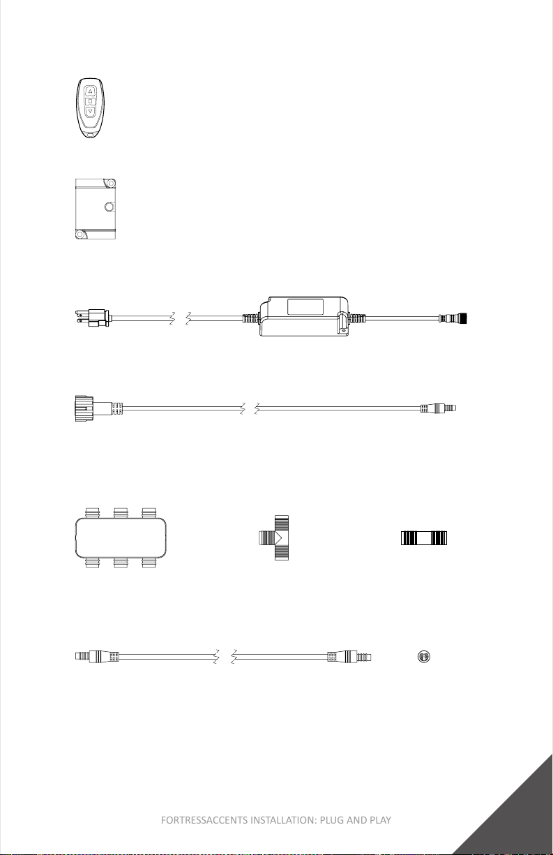
Smart Controller
3”[76mm]x2”[51mm]x1/2”[13mm]
Lighng Components
FA 60W 22-2GA PNP Adapter
20’[6096mm]
Plug and Play Components
Wire
FA-PNPFemale
6-waySplier
FA-PNP
FemaleT-Splice
FA-PNP
Female-To-FemaleConnector
60W Transformer
OutputWire6”[152mm],InputWireWithPlug5’[1524mm]
FA - PNP 22 GA LED Light Wire - Male Ends
5’[1524mm],10’[3048mm],15’[4572mm],20’[6096mm]
Remote Controller
Word Abbreviaons:
FA=FortressAccents PNP=PlugandPlay LED=Light-EmingDiode
GFCI=GroundFaultCircuitInterrupter GA=Gauge
6
FORTRESSACCENTS INSTALLATION: PLUG AND PLAY
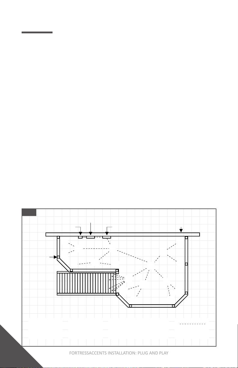
INSTALLATION: PROJECT PLANNING
Step 1: Design Wire Layout
1. Sketchoutlineofdeck.
2. IdenfylocaonofGFCIOutlet.If no GFCI Outlet, one will
need to be installed.
3. Determinelighngtobeusedandlayout/placementof
lighngondeck.Referencelightoponsonpage4.
4. Determinewhatwireconnectorswillberequiredforyour
project.Designwirelayoutsothataminimumamountof
connectorswillberequired.Referencewireconnectorson
page5.
5. Determinethebestlocaonforthetransformerbasedon
yourlighnglayout.Thetransformershouldbelocated
within15’[4572mm]oftherstLEDLight.
6. DeterminedesiredplacementoftheSmartController(if
applicable).TheSmartControllershouldbeposionedata
locaonthatallowsfortheoutputwiretobeeasilyfed
underneaththedecking.
7. Sketchdesiredwirelayout,Lighng,Transformer
and SmartControllerplacement.AsshowninFig.1.
Fig. 1
1.
FA-PNPFemale
6-waySplier
2.
FA-PNP
FemaleT-Splice
3.
FA-PNP
Female-To-FemaleConnector Wire
3.
2.
3.
3.
Top View
GFCIOutlet SmartController
Transformer
Wall/House
Post
3.
2.
3.
3.
3.
2.
3.
3.
1.
2. 1.
1.
3.
2.

7
FORTRESSACCENTS INSTALLATION: PLUG AND PLAY

8
FORTRESSACCENTS INSTALLATION: PLUG AND PLAY
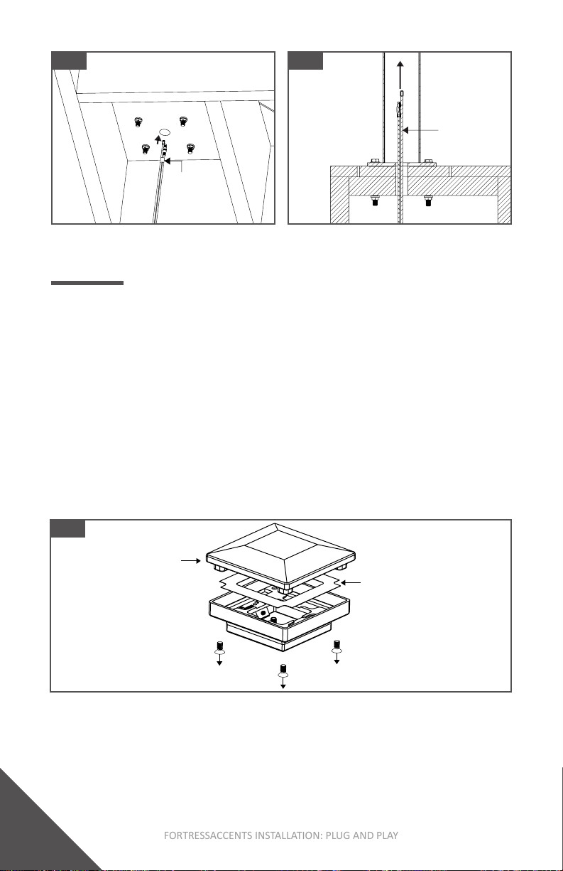
Step 2: Cut Out Post Hole In Deck
1. IdenfypoststhatwillhaveFApostGlowRing,CapLightor
VercalPostLightsinstalled.
2. Locatepostblocking/boltlocaonunderneathdecksurface.
3. Determinecenterbetweenfourbolts.
4. Measureandmarkacirclecenteredbetweenthefour
boltswitha1”[25mm]diameter.AsshowninFig.2.
5. Usinga3/4”[19mm]drillBit,drillholethroughdeck
surface.AsshowninFig.3.
Note:
• RailingshouldbeinstalledpriortoFortressAccentsPlug
andPlayinstallaon.
Fig.3Fig.2
INSTALLATION: WIRE SETUP
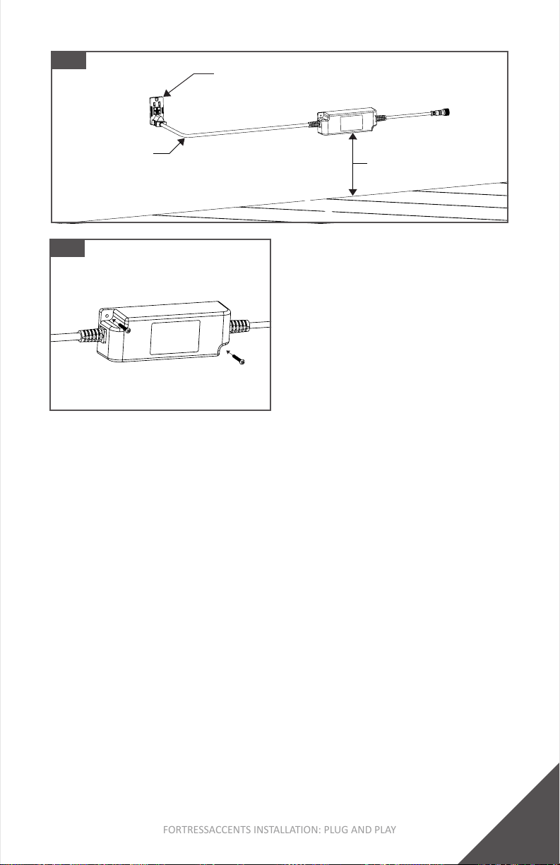
Step 1: Install Transformer
1. Thetransformermustbeinstalledataminimumof12”
[305mm]abovethegroundandclosetotheGFCIOutlet
(inputwireis5’[1524mm]long).AsshowninFig.4.
2. Placetransformerindesiredlocaonandusetheprovided
screwstomount.AsshowninFig.5.
Tip:
• Thesuppliedinputwirewithplugmustbeconnectedtoa
GFCIprotectedoutletwithahoodedushtypecoverplate
receptaclemarked“WetLocaon”. DO NOT use an
extensioncord.IfnoGFCIprotectedoutletwithahooded
ushtypecoverplatereceptaclemarked“WetLocaon”
isavailable,alicensedelectricalcontractormustinstalla
GFCIoutletattherequiredlocaon.
Boom View
1”
[25mm]
9
FORTRESSACCENTS INSTALLATION: PLUG AND PLAY
Step 2: Install Smart Controller (If Applicable)
1. ConnecttheFA-PNPAdaptertothetransformeroutput
wirewiththethreadedconnector. AsshowninFig.6.
2. ConnecttheFA-PNPAdaptertotheSmartControllerinput
wire.AsshowninFig.7.
3. PlaceSmartControllerindesiredlocaonandusethe
providedscrewstomount.AsshowninFig.8.
Tip:
• PlacetheSmartControllerinalocaonthatallowsfor
wirestobeeasilyhiddenandfedthroughtotheunder
sideofthedeck.
• Controllerisdesignedtobemountedontomulple
surfaces(Wall,Postetc).
• Ifmountedontopost,inputandoutputwirescanbefed
andhiddeninsidepost.
• Itiscricaltomaintainpolaritywhenmakingconnecons.
AsshowninFig.9.
GFCIOutlet
Minimum12”[305mm]
Fig.5
Fig.4
5’[1524mm]
InputWire

10
FORTRESSACCENTS INSTALLATION: PLUG AND PLAY
Fig.8
Fig.7Fig.6
Transformer
OutputWire
FAPlugandPlay
Adapter
• InaddiontotheSmartController,theFortressAccents
PNPsystemalsooersanaddionalRemoteController.As
showninFig.10.
FA-PNPAdapter
SmartController
InputWire
Fig.9
Transformer To FA - PNP Adapter Connecon FA - PNP Adapter To Controller Connecon
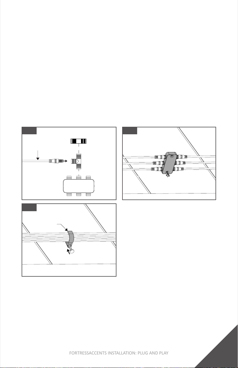
Step 3: Connect Wires
1. FeedtheSmartControlleroutputwiretotheundersideof
thedeck.
2. SecureSmartControlleroutputwiretodesiredwire
connector.AsshowninFig.11.
3. Buildoutwireconneconsbasedonthewirelayout
designedintheprojectplanningstepsonpages6&7.
Fig.10
Front View
RemoteController
Dimcontrol
(Dimlightsup)
Dimcontrol
(Dimlightsdown)
Power control
(Lightson/o)
Maintain Polarity
Besureinternalprolesofconnectorsare
orientatedinthesamedireconwithat
edgeofbothconnectorsfacingdown.
11
FORTRESSACCENTS INSTALLATION: PLUG AND PLAY
Tip:
• TheFA-PNPFemale6-waySpliercanbemountedtothe
undersideofthedeckusingtheprovidedscrews.As
showninFig.12.
• OrganizeandmanagewiresbyusingCableClips.Asshown
inFig.13.
• Beforestarngwireconnecons,surveyundersideofdeck
anddeterminebestlocaonstomounttheFA-PNP
Female6-waySplierandCableClips.
• Amale-to-malewirewillberequiredifcreanga
conneconbetweentwoconnectors.Reference connector
oponsonpage5.
Fig.11
or
or
Smart Controller
Output Wire
FA-PNPFemale
6-waySplier
FA-PNP
FemaleT-Splice
FA-PNP
FemaleToFemaleConnector
Fig.12
Fig.13
Step 4: Feed Wires Through Post or deck cut out
1. TapetheWireandtheFishTapetogether.
2. FeedFishTapeandWireupwardthroughthedeckcutout
andpost.AsshowninFig.14&15.
Cableclip
12
FORTRESSACCENTS INSTALLATION: PLUG AND PLAY
Fig.14 Fig.15
Secon View
FeedWire&
FishTape
upwards
throughpost
TapeWire
&FishTape
together
Step 1: Dis-assemble Flat Pyramid Cap
1. Removethe4machinescrews,locatedateachcorner.As
showninFig.16.
2. RemovethePostCapandInsectScreen.DO NOT discard
thescrews.
Note:
• Thefollowingcomponentsareincludedwiththe
FortressAccentsFlatPyramidCaps:PostCap,PostCap
Base,Insect Screen,4-MachineScrews,4-HexHead
SetScrews,anda2.5mmHexWrench.
INSTALLATION (METAL POST): FLAT PYRAMID CAP - NO LIGHTS
(2” [51mm] & 3” [76mm])
Fig. 16
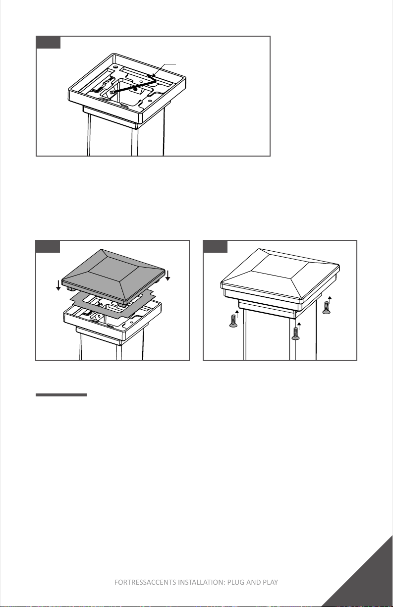
Step 2: Mount Post Cap Base
1. MountthePostCapBaseontothepost.
2. Usingthesupplied2.5mmAllenWrench,ghtenthefour
setscrews.AsshowninFig.17.
3. AdjustthescrewstocenterandlevelthePostCaponthe
post.
PostCap
Insect Screen
13
FORTRESSACCENTS INSTALLATION: PLUG AND PLAY
Fig. 17
Step 3: Install Post Cap
1. Place the Insect ScreenbackontoPostCapBase.Posion
thePostCapontothePostCapBase.AsshowninFig.18.
2. SecurePostCapwiththe4MachineScrewsthatwere
removedinstep1.AsshowninFig.19.
Fig. 18 Fig. 19
2.5mmAllenWrench
INSTALLATION (METAL POST): LED CAP LIGHT KIT
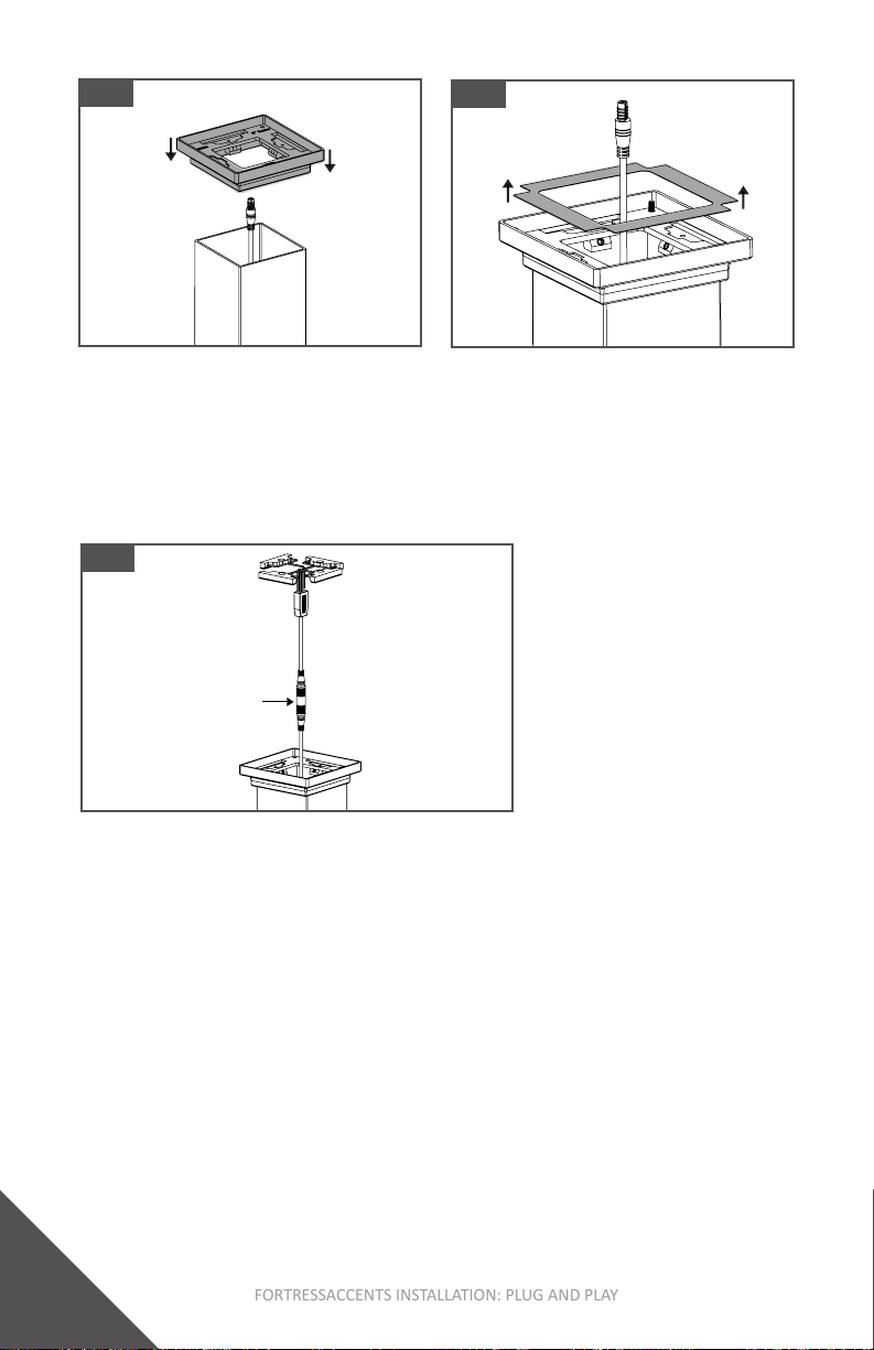
Step 1: Install Post Cap Base
1. MountthePostCapBaseontothepost. Asshownin
Fig.20.
2. Referencestep2“MountPostCapBase”onpages12&13
forinstruconsonhowtosecurethePostCapBasetothe
Post.
3. RemovetheInsectScreenfromtheFortressAccentsPost
CapBase. AsshowninFig.21.
Note:
• AnLEDCapLightKit and LED Glow Ring canbeinstalled
togetherinthesameFortressAccentsFlatPyramidCap
forcapsizesgreaterthan2”[51mm].
14
FORTRESSACCENTS INSTALLATION: PLUG AND PLAY
Fig. 21
Step 2: Connect Light Wire To LED Cap Light Kit Wire
1. ConnectwiresbyusingaFA-PNPFemale-To-Female
Connector.AsshowninFig.22.Wireconneconscanalso
bemadebelowthedecksurface.
2. Onceconnected,tuckexcesswiresintopost.
Fig. 22
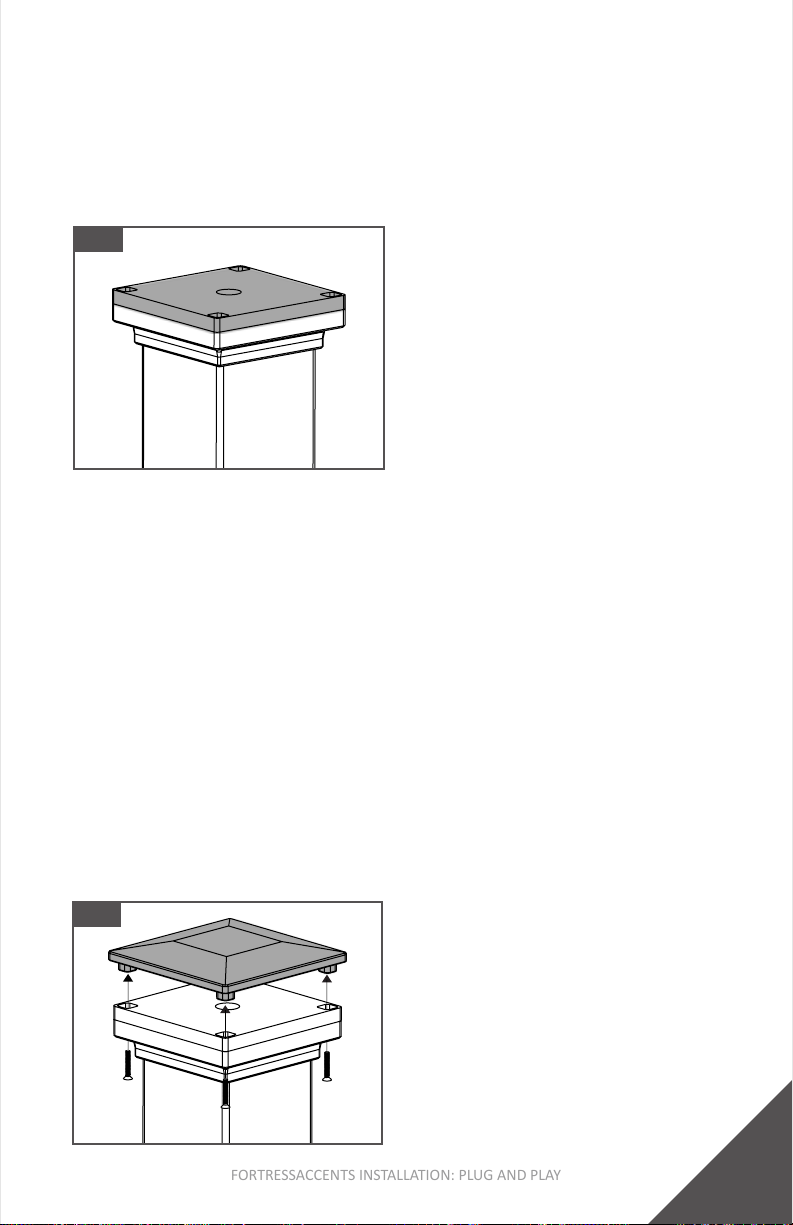
Step 3: Mount LED Cap Light Kit
1. InserteachLEDCapLightintoaslotholeonthePostCap
BasewiththeLED’sfacingdown.AsshowninFig.23.
2. SecuretheLEDCapLightKitwithprovidedscrew.As
showninFig.24.
Tip:
• If a slot holeinthePostCapBasewillnotbeusedtoemit
light,mounttheappropriateCapLightippedupsidedown
withthelightfacingup.AsshowninFig.25.Thiswillallow
theslotholetobecoveredwhilealsostoptheCapLight
fromeminglight.
Fig. 20
FA-PNP
Female-To-Female
Connector

15
FORTRESSACCENTS INSTALLATION: PLUG AND PLAY
Top View
Fig. 23 Fig.24
Fig. 25
CapLightmounted
withlightfacingup
Step 4: Install Post Cap
1. TurnontheSmartController(ifapplicable)toturnonthe
lightsandverifythatthewiringiscorrect.
2. PosionthePostCapontothePostCapBase.
3. SecurethePostCapontothePostBaseCoverwiththe
provided4MachineScrews.AsshowninFig.26.
Tip:
• IfusingSmartController,referencepages27-30 for Tuya
Smartapppairingprocess.
• IfnotusingSmartController,lightscanbeturnedonby
pluggingtransformerplugintoGFCIOutlet.
Fig. 26

16
FORTRESSACCENTS INSTALLATION: PLUG AND PLAY
INSTALLATION (METAL POST): LED GLOW RING
Step 1: Install Post Cap Base
1. MountthePostCapBaseontothepost.Asshownin
Fig.27.
2. Referencestep2“MountPostCapBase”onpages12&13
forinstruconsonhowtosecurethePostCapBasetothe
Post.
3. RemovetheInsectScreenfromtheFortressAccentsPost
CapBase.AsshowninFig.28.
Note:
• AnLEDGlow Ring and LED CapLightKitcanbeinstalled
togetherinthesameFortressAccentsFlatPyramidCapfor
capsizesgreaterthan2”[51mm].
Fig. 27
Step 2: Connect Light Wire To LED Glow Ring Wire
1. ConnectwiresbyusingaFA-PNPFemale-To-Female
Connector.AsshowninFig.29.Wireconneconscan
alsobemadebelowthedecksurface.
2. Onceconnected,tuckexcesswiresintopost.
Fig. 29
Fig. 28
FA-PNP
Female-To-Female
Connector
17
FORTRESSACCENTS INSTALLATION: PLUG AND PLAY
Step 3: Test Fit LED Glow Ring
2. BoomedgeofLEDGlowRinglenswillsitatonthetop
edgeofPostCapBase.Ifthereisagap,adjustthescrews
toallowforpropertofLEDGlowRinglens.Protect edges
ofLEDGlowRinglensfromscratchingduringinstallaon.
Fig. 30
Step 4: Install Post Cap
1. Beforeinstallingthepostcap,recheckthetoftheLED
GlowRingontothePostCapBase.
2. TurnontheSmartController(ifapplicable)toturnonthe
lightsandverifythatthewiringiscorrect.
3. AlignthePostCapscrewbosseswiththeholeslocatedat
eachcorneroftheLEDGlowRing.
4. InstallthePostCapCoverwiththefastenersprovidedwith
theLEDGlowRing.AsshowninFig.31.
Tip:
• IfusingSmartController,referencepages27-30forTuya
Smartapppairingprocess.
• IfnotusingSmartController,lightscanbeturnedonby
pluggingtransformerplugintoGFCIOutlet.
Fig. 31

18
FORTRESSACCENTS INSTALLATION: PLUG AND PLAY
INSTALLATION (METAL POST): LED VERTICAL POST LIGHT
Step 1: Drill LED Vercal Post Light Wire Hole
1. PlacetheLEDVercalPostLightBaseonthepostatthe
desiredlocaon.TheLEDVercalPostLightshouldbe
installedaminimumof12”[305mm]abovegroundlevel.
AsshowninFig.32.
2. Usingapencil,tracetheholepaernontothepost.As
showninFig.33.
3. Markthecenterpointoftheholepaernanddrilla1/2”
[13mm]diameterholeinpost.
Tip:
• Besuretoremoveanymetalshavingsfromthesurfaceof
deck,paoorbalconytopreventrustonthesurface.
Fig. 32
Step 2: Mount LED Vercal Post Light Base
1. Pre-drillscrewholesusinga5/32”[4mm]drillbit.
2. AachLEDVercalPostLightBasetopostwithsupplied
screwsthenfeedwirethroughpostcutout.Asshownin
Fig.34.
Installed a
Minimumof
12”[305mm]
aboveground
Fig. 34
Fig. 33
19
FORTRESSACCENTS INSTALLATION: PLUG AND PLAY
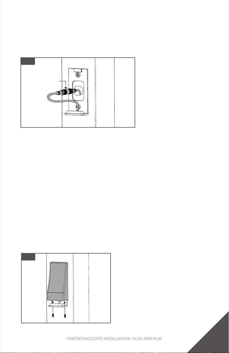
Step 3: Connect Light Wire To LED Vercal Post Light Wire
1. ConnectwiresbyusingaFA-PNPFemale-To-Female
Connector.AsshowninFig.35.Wireconneconscan
alsobemadebelowthedecksurface.
Fig. 35
FA-PNP
Female-Female
Connector
Step 4: Install LED Post Vercal Post Light Cover
1. Tuckwiresinsidepostcutout.
2. PlaceLEDVercalPostLightCoverovertheinstalledLED
VercalPostLightBaseandslidedownwardunlcoveris
fullyinplace.
3. TurnontheSmartController(ifapplicable)toturnonthe
lightsandverifythatthewiringiscorrect.
4. Usingthetwosuppliedmachinescrews,securethecover
tothebase.AsshowninFig.36.
Tip:
• IfusingSmartController,referencepages27-30 for Tuya
Smartapppairingprocess.
• IfnotusingSmartController,lightscanbeturnedonby
pluggingtransformerplugintoGFCIOutlet.
Fig. 36
20
FORTRESSACCENTS INSTALLATION: PLUG AND PLAY
INSTALLATION (METAL POST): LED SURFACE MOUNT LIGHT
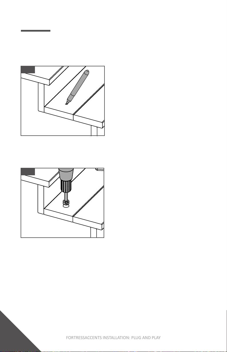
Step 1: Mark Desired LED Surface Mount Light locaon
1. PlacetheLEDSurfaceMountLightinthedesiredlocaon.
2. Usingapencil,markthecenterpoint.AsshowninFig.37.
Fig. 37
Step 2: Drill LED Surface Mount Light Hole
1. UsingaForstnerBit,drilla1”[25mm]holeonthe
previouslymarkedcenterpoint.AsshowninFig.38.
Fig. 38
Step 3: Connect Light Wire To LED Surface Mount Light Wire
1. ConnectwiresbyusingaFA-PNPFemale-To-Female
Connector.AsshowninFig.39.Wireconneconscan
alsobemadebelowthedecksurface.
Table of contents
Popular Outdoor Light manuals by other brands


brennenstuhl
brennenstuhl SGF2 DA 96 S DE 3993 operating instructions

Inlite
Inlite FISH EYE 100 manual

Delta Light
Delta Light SONAR 105 T18 A-ANO quick start guide

heatco
heatco JAMMY O-0005-WUP instruction manual

HAMPTON BAY
HAMPTON BAY NEWBERRY LDO1601AX-01/CP Use and care guide

oneConcept
oneConcept 10027647 user manual

HAMPTON BAY
HAMPTON BAY 596-897 instruction manual

HAMPTON BAY
HAMPTON BAY 62113 Use and care guide

Inlite
Inlite ACE UP-DOWN installation manual

MegaLite
MegaLite HELIUS L Series Instructions for installation

ledscom
ledscom LC-EL-125-WW Assembly instructions

NewGarden
NewGarden MYKONOS HANG Assembly and maintenance manual