Fortress Technologies EVOLUTION STEEL PERGOLA User manual

EVOLUTIONTM STEEL PERGOLA
INSTALLATION INSTRUCTIONS

PERGOLA INSTALLATION: EVOLUTION
2
PERGOLA INSTALLATION: EVOLUTION
3
General Guidelines...............................................................3
Required Tools/Components...............................................4
Project Planning...................................................................6
...........................................................7
Pergola
.....9
Post to Framing Member........................................11
Post to Framing Member (F-50 Bracket)................11
P
Bracket)..................................................................12
Post to Single or Double Beam Joists.....................13
Post to Material (Composites, Lumber,
Joists etc)...............................................................14
Lateral Bracing Assembly........................................15
19
Single or 22
23
..................................24
Joist/Framing Member Cap...................................26
Purlin Cap..............................................................27
Post Cap.................................................................27
Care & Maintenance/Warranty....................................................29
TABLE OF CONTENTS INTRODUCTION
READ INSTRUCTIONS COMPLETELY BEFORE
STARTING INSTALLATION
General Guidelines
It is the responsibility of the installer to meet all code and
safety requirements, and to obtain all required building
permits. The pergola installer should determine and
its distributors shall not be held liable for improper or unsafe
pergola parts. At the end of each
surrounding surfaces.
As the steel parts are cut, DO NOT
happen.
it may be necessary for you to consult a professional
may become necessary to use brackets other than Fortress’
PERGOLA INSTALLATION: EVOLUTION
4
PERGOLA INSTALLATION: EVOLUTION
5
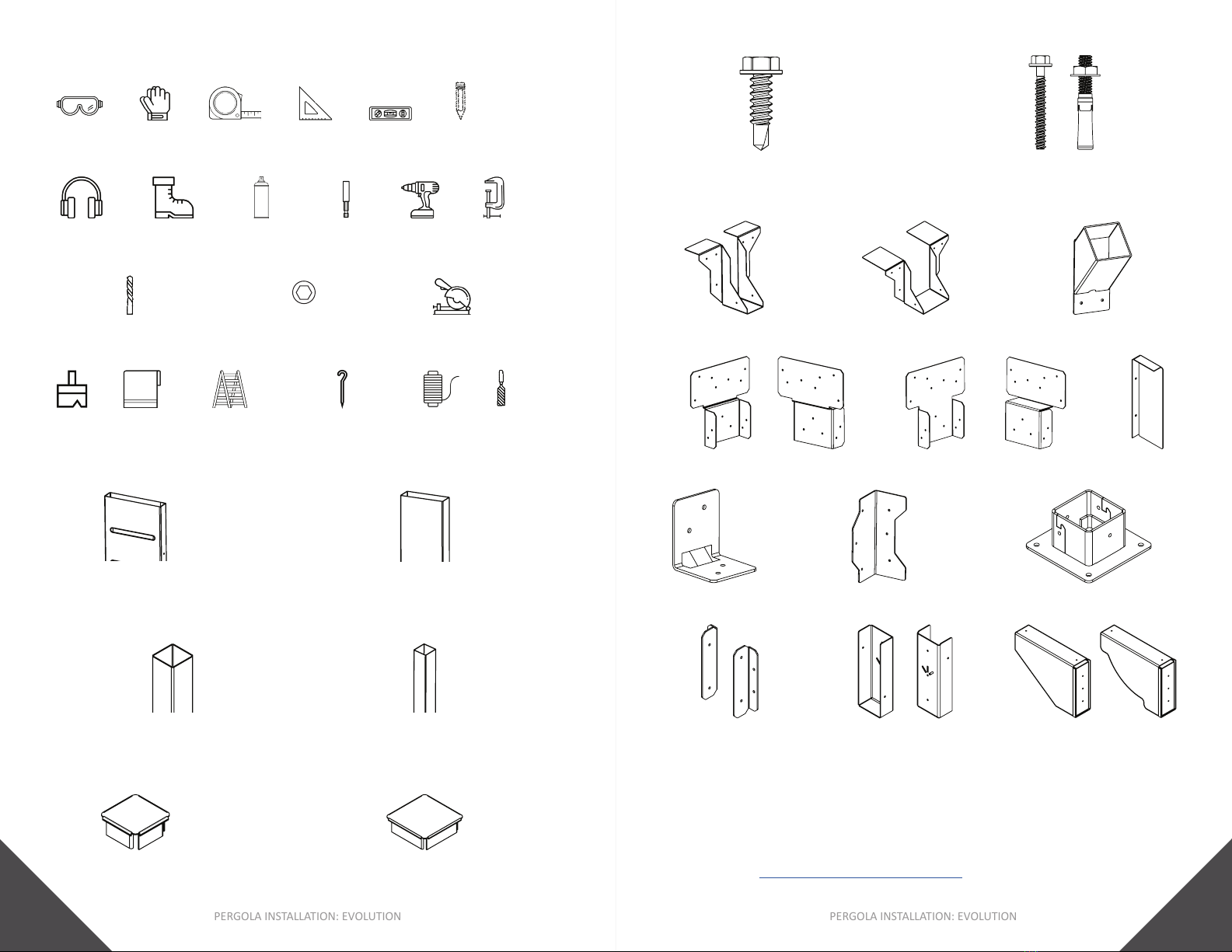
F-10 Bracket
Joist Cap
Single Hanger Bracket
Components
3/4” [19mm]
#12
Anchor
Concrete Anchor:
Wedge Anchor:
Lateral Bracing Bracket
Required Tools
Goggles
Drill
Tape
Measure
Tool
Speed
Square
Bit
Concrete Drill Bit:
5/16”, 3/8” [8mm, 10mm]
Pencil
Safety
Close-Toed
Shoes
Protector
ClampsTouch-Up
Paint
3/8”, 5/16” [10mm, 8mm]
StringGround Stakes File
Post
4877mm, 5486mm, 6096mm]
Purlin or Lateral Bracing Support
Purlin Cap
F-50 Bracket
Double Beam To Post Bracket
Step Ladders
Brush Rags
Note:
pergola designs.
Double Hanger Bracket
Beam
3658mm, 4877mm or 6096mm]
Single Beam To Post Bracket
Post Cap
CS
Bracket
Bracket
Post Anchor Bracket
PERGOLA INSTALLATION: EVOLUTION
6
PERGOLA INSTALLATION: EVOLUTION
7
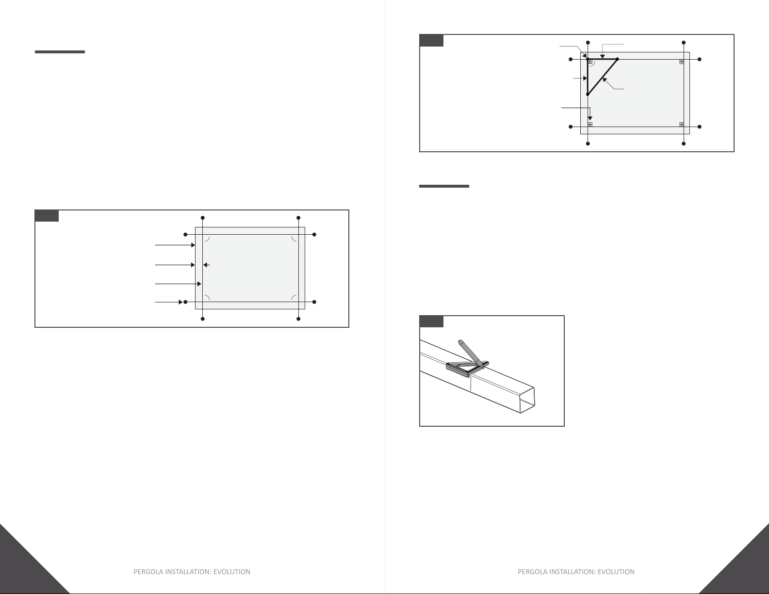
PROJECT PLANNING
Step 1: Create a Perimeter For The Pergola
1. Using Stakes and Guide String, create a perimeter for the
Tip:
•
•
Fig. 1
Guide String
Stake
Minimum 4” [102mm]
Fig. 2
4’ [1219mm]
3’ [914mm]
5’ [1524mm]
along internal
corner of Guide Strings
Step 2:
1. Post Anchor Brackets along internal corners
2.
Tip:
•
and square.
• Fortress recommends using the
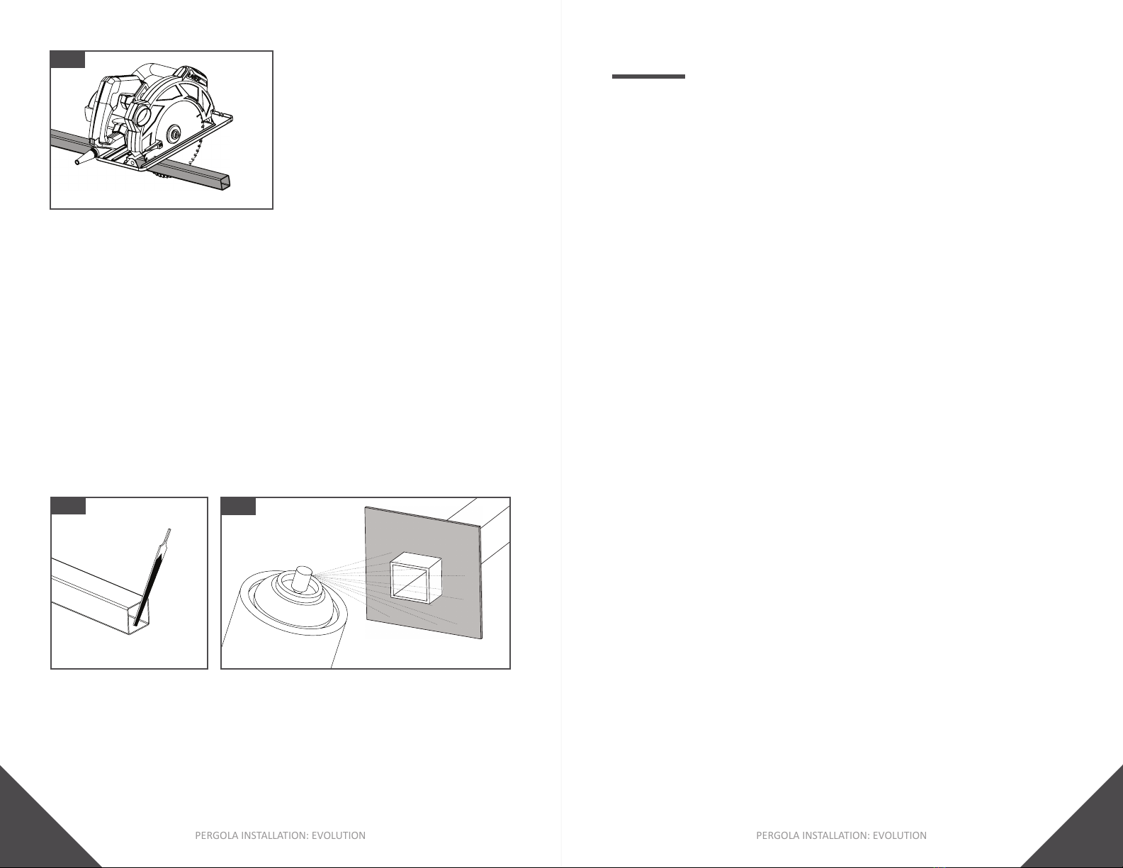
CUTTING & PAINTING
Step 1: Mark Cut Points
2. Using a pencil, mark desired length onto material being cut.
3. Using a Speed Square, straighten cut point markings on
top and side faces.
Tip:
•
Fig. 3
Step 2: Cut The Material
1. Cut the Post, Joist or Purlin using a ,
As
Tip:
•
bending or binding.
•
PERGOLA INSTALLATION: EVOLUTION
8
PERGOLA INSTALLATION: EVOLUTION
9
Fig. 4
Fig. 5 Fig. 6
2X
Step 3: Clean Cut Areas & Apply Spray Paint To Cut Areas
3. Make sure surfaces to be painted are clean. DO NOT cut
4. Using a piece of cardboard as a mask, apply the 1st coat of
Fortress Black Sand Touch Up Paint.
6. Apply the 2nd coat of Fortress Black Sand Touch Up Paint.
A minimum of three coats of spray paint
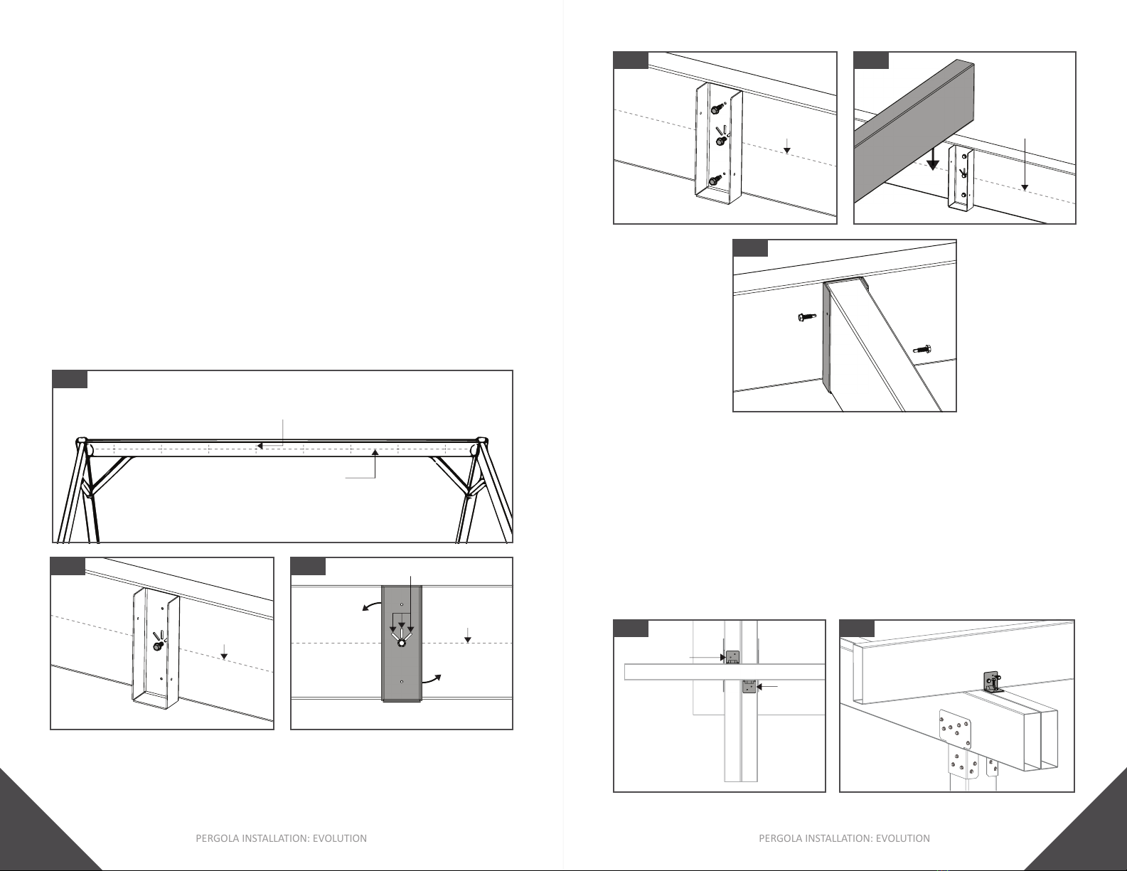
PERGOLA CONNECTIONS
concrete or slab.
4. Pre-drill holes using a concrete drill bit. Reference the
concrete anchor manufacturer for recommended
drill bit size.
5. Mount the Post Anchor Bracket onto the surface using
Post Anchor Bracket detachable
Fig. 9.
7. Insert Post into Post Anchor Bracket. Be sure post is fully
As
.
8. Mount the Post Anchor Bracket detachable
back onto the bracket slot.
Note:
• Post Anchor Brackets to
PERGOLA INSTALLATION: EVOLUTION
10
PERGOLA INSTALLATION: EVOLUTION
11
Fig. 9
Fig. 8
Fig. 7
Fig. 10
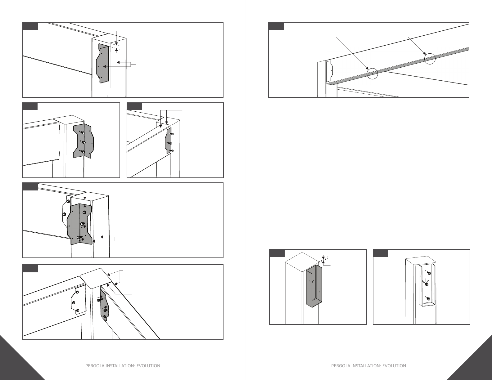
Fig. 12Fig. 11 Post To Framing Member
As
2. mount the F-50
Bracket onto the Post.
Framing Member
the Post.
4. Using , mount the F-50
Bracket onto the Framing Member.
5.
Note:
•
Adjust if required.
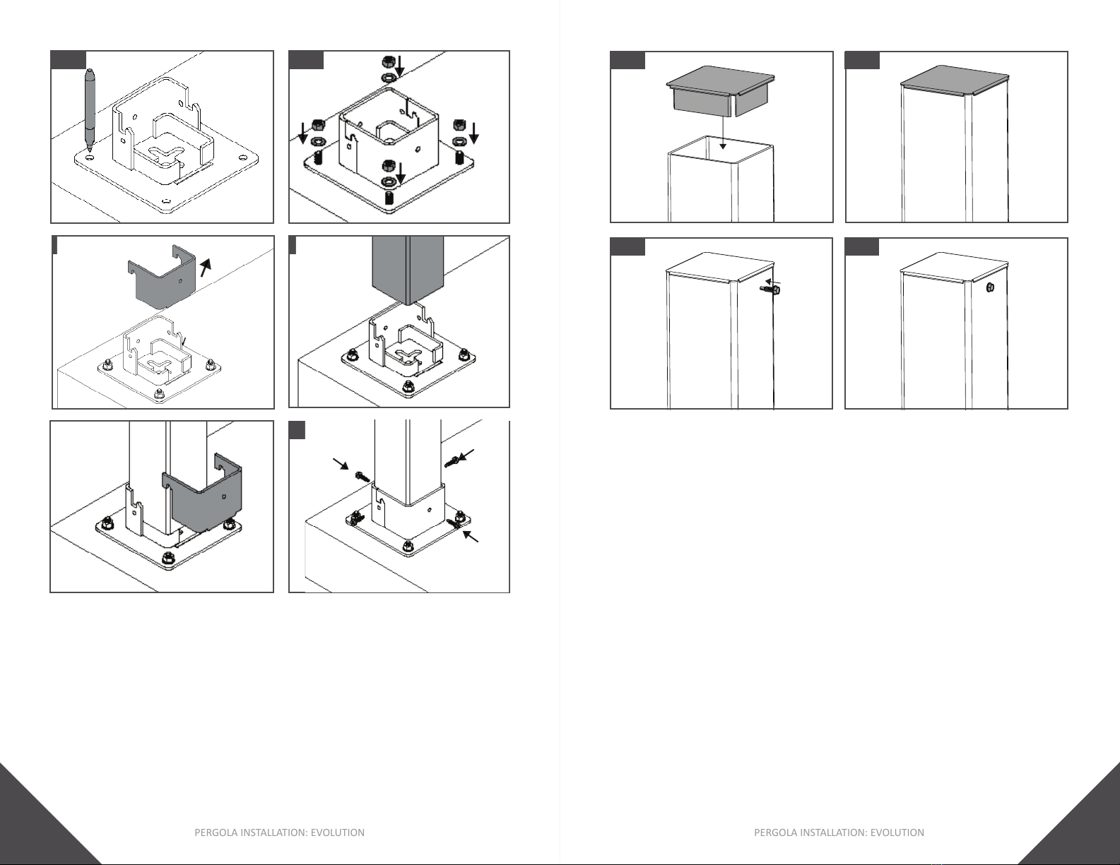
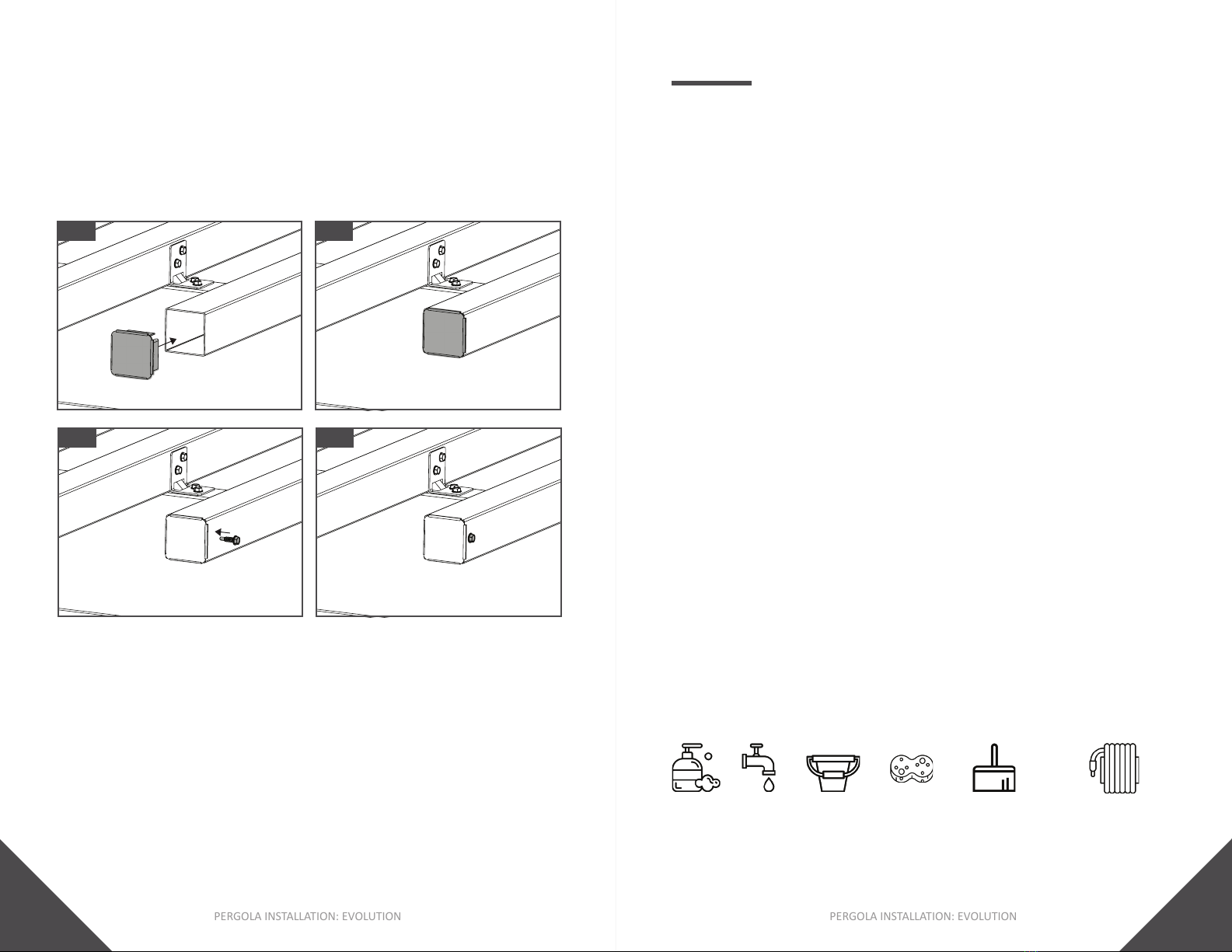
Post Cap
Post CapPost. As
If required, use a Rubber Mallet to
fully seat the Cap.
2. , fasten Cap onto the
Post
[18mm] from the end of the cap.
Note:
installing brackets.
Fig. 14Fig. 13
Fig. 16Fig. 15
PERGOLA INSTALLATION: EVOLUTION
12
PERGOLA INSTALLATION: EVOLUTION
13
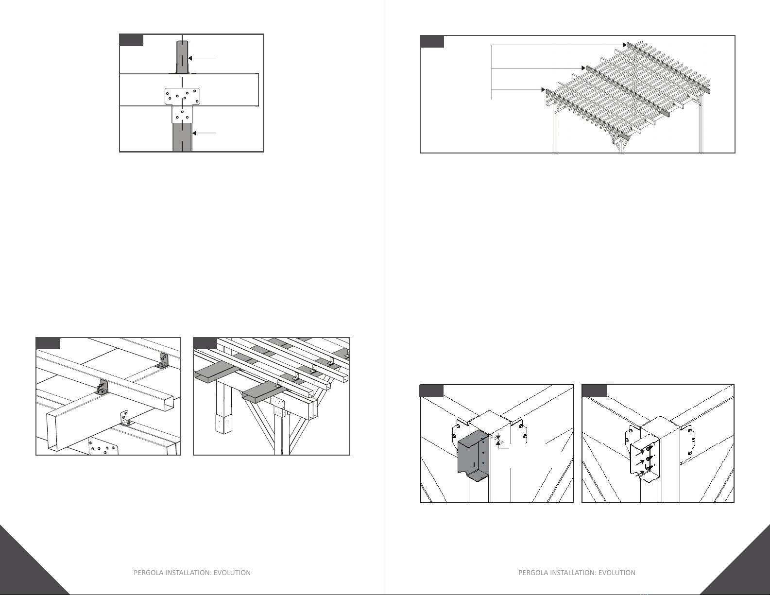
Fig. 21
Fig. 20 F-50 Bracket 7/16” [11mm] from top of Post
Fig. 22
Drainage holes
Post To Framing Member
Post to Framing Member:
[2mm] from the
top of each Post
2. mount the
onto the Post.
fastening.
3. Insert the Framing Member into the
Brackets
4. fasten the
s onto the Framing Member. As
Fig. 24
Fig. 23
1/16” [2mm]
from top of Post
Fig. 17
F-50 Bracket 7/16” [11mm] from top face of Post
edge of Post
Fig. 19Fig. 18 Top face of Framing
top face of Post
PERGOLA INSTALLATION: EVOLUTION
14
PERGOLA INSTALLATION: EVOLUTION
15
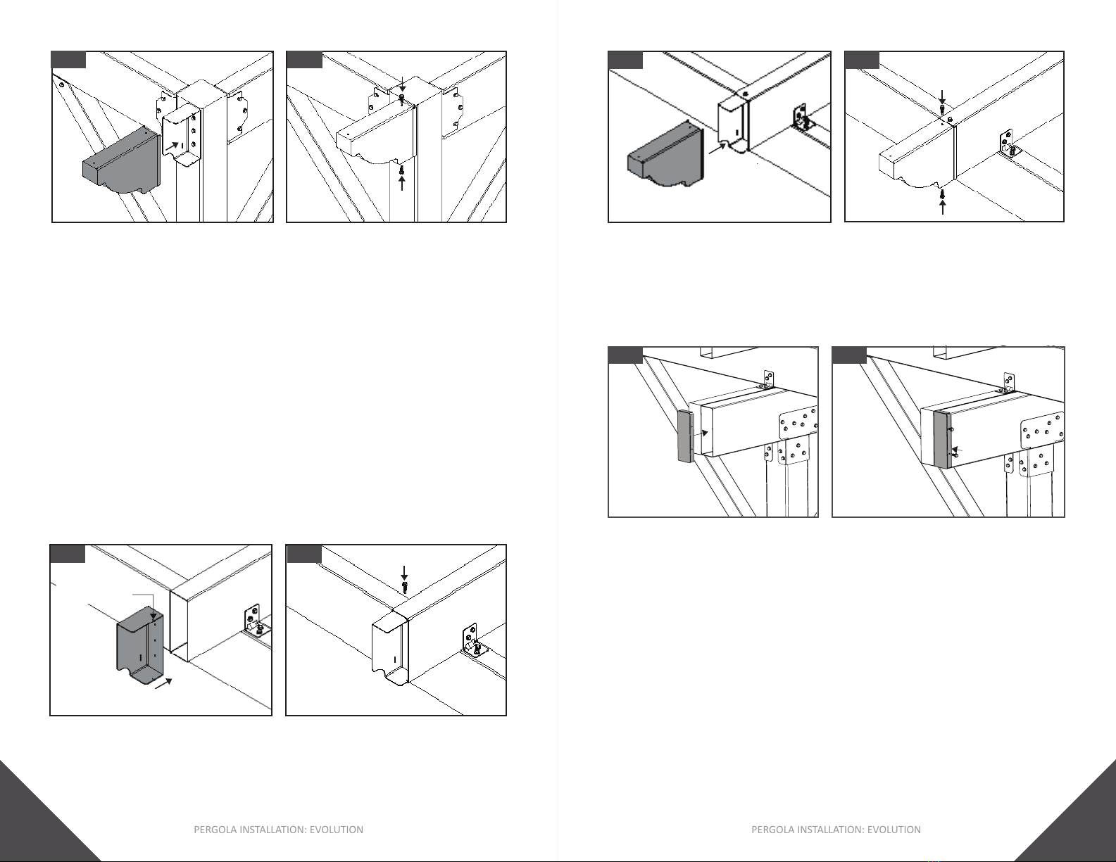
Fig. 28Fig. 27
Fig. 30Fig. 29
24” [610mm]
1. Cut material to desired length.
2. , CS Brackets
at both ends of cut material. Be sure outside face of
3.
4. , fasten CS Brackets
Note:
•
Fig. 32
Fig. 31
Fig. 25 Fig. 26
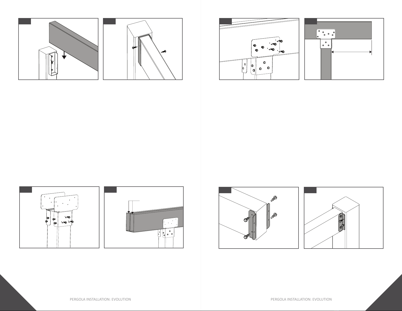
Post To Single or Double Beam Joists
1. ,
Double Beam to Post Brackets onto top edge of Post. As
Fig. 28.
Double Beam to Post Brackets
Fig. 29.
Note:
•
PERGOLA INSTALLATION: EVOLUTION
16
PERGOLA INSTALLATION: EVOLUTION
17
Fig. 34Fig. 33
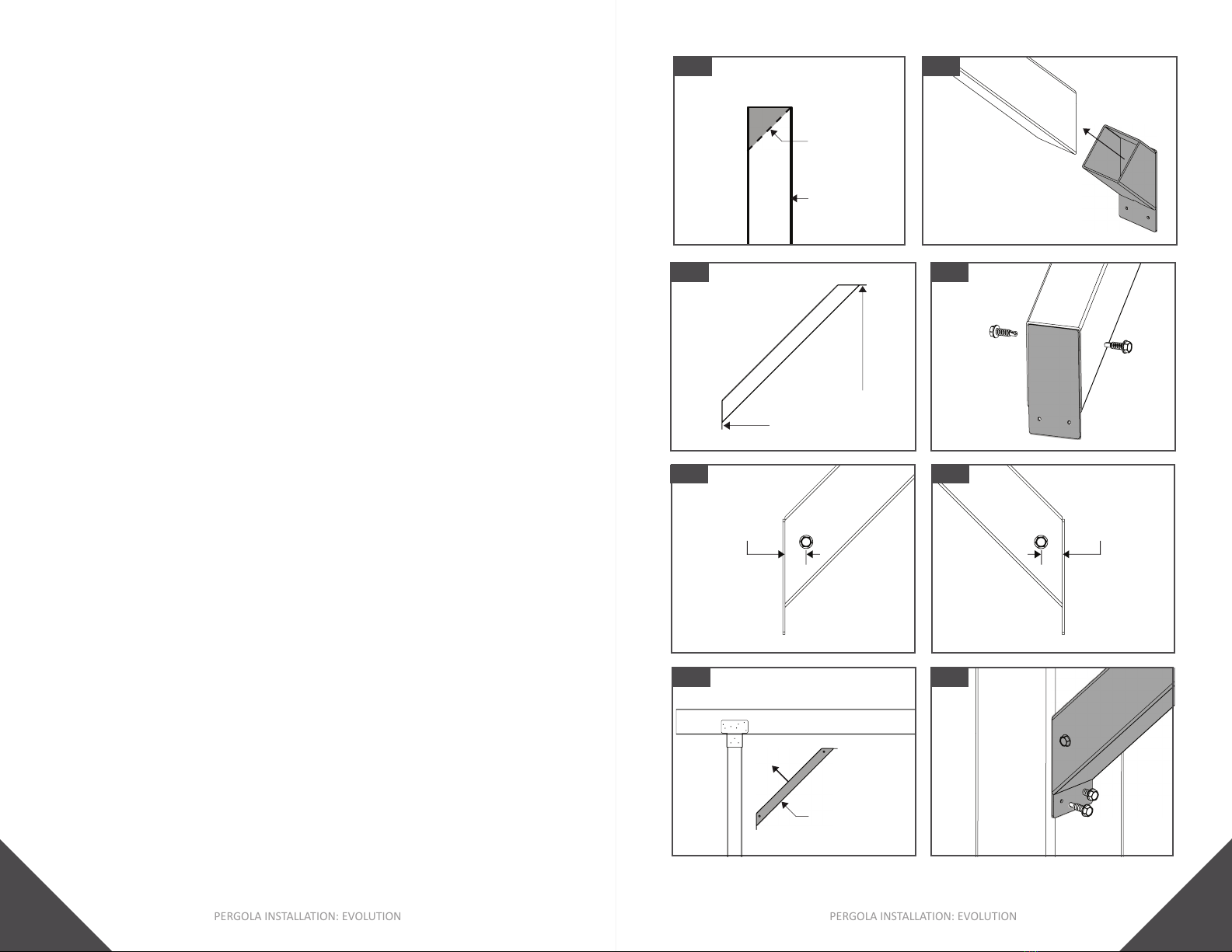
Lateral Bracing
Support
45degree
cut
Fig. 36Fig. 35
Lateral Bracing Bracket
from angle
Fig. 38Fig. 37
1” [25mm]
Fig. 40
Fig. 39
Lateral Bracing
Assembly
3/4” [19mm]
Lateral Bracing Assembly
1. Cut the to
desired length.
2. Cut both ends of the
Bracing Support at a 45o
3. Insert the Lateral Bracing Brackets into both ends of the
4. Be sure the Lateral Bracing Brackets are orientated in
Fig. 35. Adjust if needed.
5. , fasten the Lateral
Bracing Brackets onto t
Lateral Bracing Support
from the edge of the Lateral Bracing Bracket.
Fig. 36 - 38.
Lateral Bracing Assembly into the desired
45oangle
7. , fasten the Lateral
Bracing Assembly onto the Post and Framing Member or
Note:
• Purlin tubing is re-purposed as
Lateral Bracing Support.
• Lateral Bracing
Support: 24” [610mm].
PERGOLA INSTALLATION: EVOLUTION
18
PERGOLA INSTALLATION: EVOLUTION
19
Fig. 41
Fig. 42
Fig. 43
Top faces of Framing
Fig. 45
Fig. 44
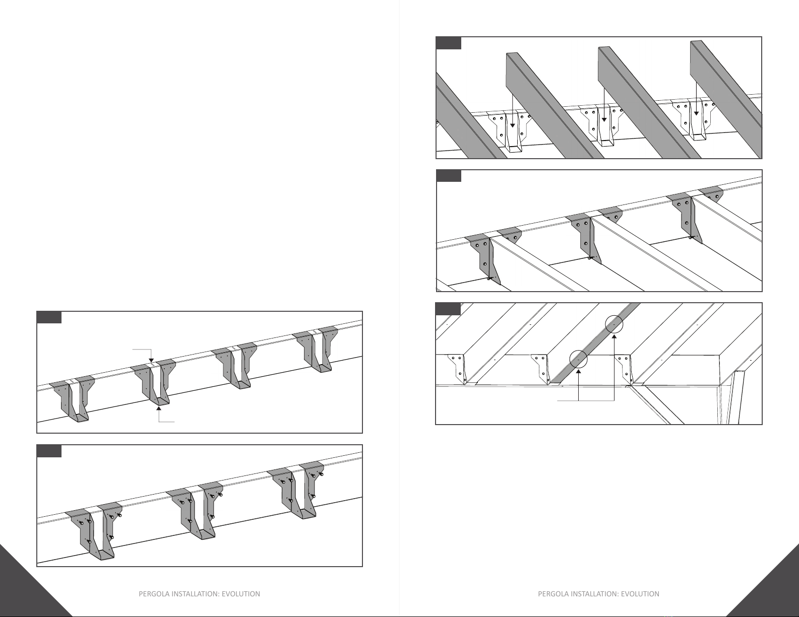
1. Measure and mark desired on-center spacing onto top
.
2. Mount the F-50 Bracket centered along on-center spacing
Fig. 41.
3.
perpendicular to the Framing Member.
4. fasten the F-50
Bracket onto the Framing Member.
5. Framing
MemberFraming
Member
6. , fasten the onto
the F-50 Bracket.
7.
Tip:
• Be sure all F-50 Brackets are orientated in the same
•
PERGOLA INSTALLATION: EVOLUTION
20
PERGOLA INSTALLATION: EVOLUTION
21
Fig. 47
Fig. 48
Fig. 49
Fig. 50
Drainage holes
1. Measure and mark desired on-center spacing onto top
.
2. Mount the Single or Double
Framing Member and centered along on-center spacing
3. , fasten the Single or
the Framing Member. As
4. Single or Double
5. , fasten the
Single or Double
in Fig. 49.
Tip:
•
Fig. 46
onto Framing Member and centered on mark
opposite Framing Members.
2. Measure and mark desired on-center spacing onto inside
.
Fig. 51.
3. , loosely fasten the
center hole of at each
PERGOLA INSTALLATION: EVOLUTION
22
PERGOLA INSTALLATION: EVOLUTION
23
Fig. 54
Fig. 53
Fig. 52
Fig. 55
Centerline
Centerline
Centerline Centerline
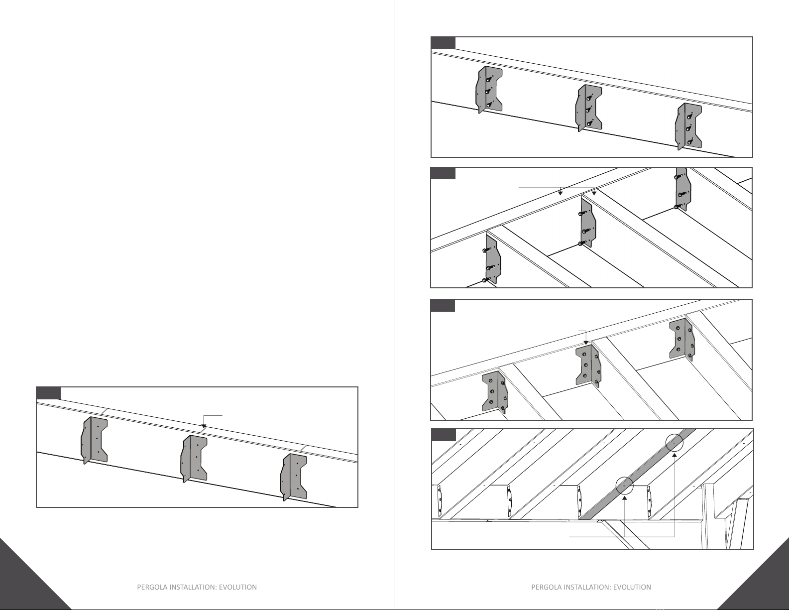
Fig. 56
Single or Double Beam Joist To
Fasten brackets using . As
Tip:
•
in Fig. 59.
Fig. 58Fig. 57
F-10 Bracket
F-10
Bracket
to desired angle.
5. , fasten the remaining
6. . As
7. , fasten the
Fig. 56.
Tip:
•
.
Fig. 51
Centerline
PERGOLA INSTALLATION: EVOLUTION
24
PERGOLA INSTALLATION: EVOLUTION
25
from the top face
of each Post
2. mount the
onto the Post.
Fig. 64. Use a Speed Square to keep
3. Slide
Fig. 65.
4. fasten the
onto the
.
in Fig. 66.
Fig. 64
Fig. 63
1/16” [2mm]
from top of Post
Fig. 61
Fig. 60
Fig. 62
F-10 Brackets mounted
Fig. 59
Joist
Post
To Purlin
1. , fasten one F-10
Bracket on each joist to Purlin
Tip:
• For each Purlin, at a minimum, F-10 Brackets should be
PERGOLA INSTALLATION: EVOLUTION
26
PERGOLA INSTALLATION: EVOLUTION
27
Joist/Framing Member Cap
2. , fasten Joist/Framing
Member
Fig. 69
Fig. 68Fig. 67
Fig. 70
Fig. 72Fig. 71
Insert up to the
punched slot
Fig. 65 Fig. 66
1. Slide the
insertminimum of
2. fasten into the
insert.
3. Slide
Tail
Fig. 69.
4. fasten the
onto the
.
PERGOLA INSTALLATION: EVOLUTION
28
PERGOLA INSTALLATION: EVOLUTION
29
CARE & MAINTENANCE
• DO NOT
• The frequency of cleaning depends in part on the standard
be used.
Cleaning Your Ultraspan Joist
Soap Water Bucket Sponge
With Fan Tip
Broom
Purlin Cap
Purlin CapPurlin. As
If required, use a Rubber Mallet to
fully seat the Cap.
2. , fasten Cap onto the
Purlin
[18mm] from the end of the cap.
Fig. 76Fig. 75
Fig. 74Fig. 73

PERGOLA INSTALLATION: EVOLUTION
30
PERGOLA INSTALLATION: EVOLUTION
31
WARRANTY
STEP 1:
STEP 2:
STEP 3:
*DO NOT use standard composite cleaners on the UltraSpan Joist.

JOIN THE REVOLUTION.
FortressBP.com | 866.323.4766
Unless otherwise noted, all proprietary names are trademarks of Fortress Iron, LP. All rights reserved.
01/2023
© 2023 Fortress Building Products.
Table of contents
Other Fortress Technologies Outdoor Furnishing manuals


Popular Outdoor Furnishing manuals by other brands


Harol
Harol VZ720 Mounting instruction

Forever Redwood
Forever Redwood DEL NORTE OUTDOOR KITCHEN PAVILION Assembly instructions

Weltevree
Weltevree Wheelbench product manual

Anova
Anova SS1001-TRI Assembly instructions

Tramontina
Tramontina LEBLON 92256 ASSEMBLY AND GENERAL INSTRUCTIONS

Patiova
Patiova varaMORA Ottoman w/Tray Assembly manual


