Fortress Technologies AI13 User manual

1
AL13 HOME TRADITIONAL PANEL INSTALLATION
INSTALLATION INSTRUCTIONS
INSTRUCTIONS D’INSTALLATION
INSTRUCCIONES DE INSTALACIÓN
TRADITIONAL ALUMINUM RAILING
RAMPE TRADITIONNELLE EN ALUMINIUM
BARANDAS DE ALUMINIO TRADITIONAL

2
AL13 HOME TRADITIONAL PANEL INSTALLATION
TABLE OF CONTENTS
English
Introduction...................................................................................3
Installation.....................................................................................5
OTP & Proud Post Installation.........................................5
Over The Top (OTP) Installation.....................................9
Proud Post Installation...................................................17
Angle Bracket Installation............................................22
Care & Maintenance.................................................................34
Warranty.....................................................................................35
Français
Introduction.................................................................................39
Installation...................................................................................41
Installation sur poteau et Proud Posts..........................41
Installation sur poteau..................................................45
Installation de Proud Posts...........................................53
Installation de ferrures à angle....................................58
Entretien......................................................................................70
Garatie........................................................................................71
Español
Introducción................................................................................75
Instalación..................................................................................77
Instalación OTP y postes salientes..............................77
Instalación sobre la parte superior (OTP)...................81
Instalación de postes salientes....................................89
Instalación de soporte en ángulo................................94
Cuidado y mantenimiento.......................................................106
Garantía....................................................................................107

3
AL13 HOME TRADITIONAL PANEL INSTALLATION
INTRODUCTION
READ INSTRUCTIONS COMPLETELY BEFORE
STARTING INSTALLATION
It is the responsibility of the installer to meet all code and
safety requirements, and to obtain all required building
permits. The deck and railing installer should determine and
implement appropriate installation techniques for each
installation situation. Fortress Railing Products and its
distributors shall not be held liable for improper or unsafe
installations.
Fortress AL13 HOME posts must always be secured to the deck
framing and should never be attached to only the deck
boards.
Note
When cutting Fortress railing, it is very important to complete
the following at cut points:
• Remove all metal shavings from the cut area.
• File any sharp edges left by cutting. Thoroughly wipe and
remove any filings, grime or dirt from the railing.
• Apply two coats of Fortress zinc based touch-up paint to the
cut area. If touch up is at rail ends, allow paint to dry before
connecting bracket to post.
• Be sure to remove any metal shavings from the surface of
deck, patio or balcony to prevent stains on the deck surface.
Torx Safety Tips
• Always use the lowest speed setting on drill.
• To reduce chance of bit breakage, start tightening with drill on
low torque setting and work up until screw is secured.
Tip: Pre-drill holes with 3/16” [4.5mm] drill bit.

4
AL13 HOME TRADITIONAL PANEL INSTALLATION
Required Tools
Goggles
Drill
Tape
Measurer
Level
Tool
Speed
Square
Touch-Up
Paint
Miter Saw
T-25
Driver Bit
#2 Phillips
Head Bit
Crescent
Wrench
Bit
Extender
5/16” [8mm]
Nut Driver Bit
Drill Bits:1/16”,
3/16”, 3/8”, 5/8” [1.5mm,
4.5mm,9.5mm, 16mm]
Al13 HOME Traditional Installation Options
Over The Post (OTP)
Socket
Set
Pencil
Rubber
Mallet
Hex
Wrench
Flat ATR
Line Splice
Round ATR
Line Splice
Flat Accent Top Rail
Round Accent Top Rail
Post
Pre-attached
Straight Brackets
2” [51mm]
Post
Post
Pre-attached
Straight Brackets
Post Base Cover
Flat ATR
End Splice
Round ATR
End Splice
I-Support
Al13 HOME Panels
69.5” [1763mm] or 93.5” [2375mm]
Spring
Punch

5
AL13 HOME TRADITIONAL PANEL INSTALLATION
Proud Post
Step 1: Install Wood Blocks
1. Install Wood Block level with top of joist. As shown in Fig.1(A)
2. Secure Wood Block to blocking on all four sides with #10 X
3-1/2” [89mm] deck screws.
• Wood Block must be constructed with treated dimensional
lumber with a minimum thickness of 1 1/2” [38mm].
OTP & PROUD POST: POST MOUNTING
Step 2: Position Base Plate
1. Position the edge of AL13 HOME base plate a minimum of ½”
[12.5mm] from the inside edge of rim joist. As shown in Fig. 1.
*If using Fortress Evolution Framing, contact Fortress for instructions.
Fig. 1
#10 x 3-1/3”
[84.5mm]
(A)
(A)
Joist
Blocking
Flat Accent Top Rail
Round Accent Top Rail
Post Cap
Post
Pre-attached
Straight Brackets
3” [76mm]
Post
Post Base Cover
Post
Pre-attached
Straight Brackets
I-Support
Al13 HOME Panels
69.5” [1763mm] or 93.5” [2375mm]

6
AL13 HOME TRADITIONAL PANEL INSTALLATION
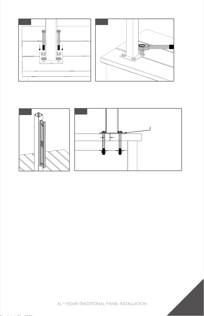
Step 4: Mount Posts
1. Mark mounting hole locations and pre-drill a 3/8” [9.5mm]
hole.
2. Insert 3/8” x 3-1/2” [9.5mm x 89mm]Hex Head galvanized
bolts through 3/8” [9.5mm] galvanized washer and post
base plate.
Note:
• Post Base Plate holes MUST be positioned a minimum ½”
[12.5mm] from edge of deck board.
• Use only 3/8” [9.5mm] Hex Head Galvanized Bolts. Lag
Screws should NOT be used. Secure each post with four bolts.
Fig. 1
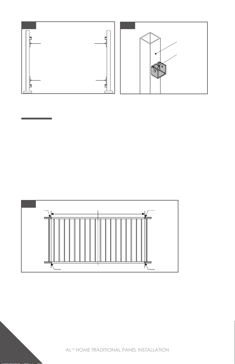
Step 3: Max Post Spacing
• 8’ panel maximum post spacing is 93-3/4” [2381mm].
• 6’ panel maximum post spacing is 69-3/4” [1771.5mm].
Note:
• Do not exceed the maximum post spacing.
Fig. 1
1/2” [12.5mm]
1/2”
[12.5mm]
8’ panel maximum post spacing is 93-3/4”
[2381mm]
6’ panel maximum post spacing is 69-3/4”
[1771.5mm]
7
AL13 HOME TRADITIONAL PANEL INSTALLATION
Step 5: Check Mounted Posts
1. Shim post as needed to ensure post is level.
Fig. 1
Fig. 1 Fig. 2
Step 6: Measure The Panel Opening Length
1. Measure the distance of the panel opening. As shown in Fig. 1.
2. Confirm that the measurements for the top brackets are the
same as the bottom brackets.
Note:
• Measure from the back wall of the bracket to the
back wall of the bracket on other post. As shown in
Fig. 2.
OTP and Proud Post: Max Post Spacing
• 8’ panel maximum post spacing is 93-7/8”.
• 6’ panel maximum post spacing is 69-7/8”.
Note: Do not exceed the maximum post spacing.
8’ Panel max post spacing 93-7/8”
6’ Panel max post spacing 69-7/8”
OTP and Proud Post: Measuring The Panel Opening Length
• Measure the distance of the panel opening.
• Measure from the back wall of the bracket to the back wall of the bracket on other post.
• Confirm that the measurements for the top brackets are the same as the bottom brackets.
Measure the panel opening
Not here
Measure from
back of bracket
Check measurement with top
3/12
Fig. 2
Shim post as needed to
ensure post is level
Deck Board
Rim Joist
Joist / Blocking
Wood Block 1/2”
[12.5mm]
8
AL13 HOME TRADITIONAL PANEL INSTALLATION
OTP & PROUD POST: CUTTING DOWN PANELS
Step 1: Measure & Mark Panels Where Cuts Will Be Made
1. To ensure panel is symmetrical, take the measurement found
on page 7 step 6 and divide it in half. Then cut equal lengths
from both ends.
2. Find the center of the panel and measure out half of the length
each direction.
3. Mark these locations with a pencil on the top and bottom rail.
Fig. 1
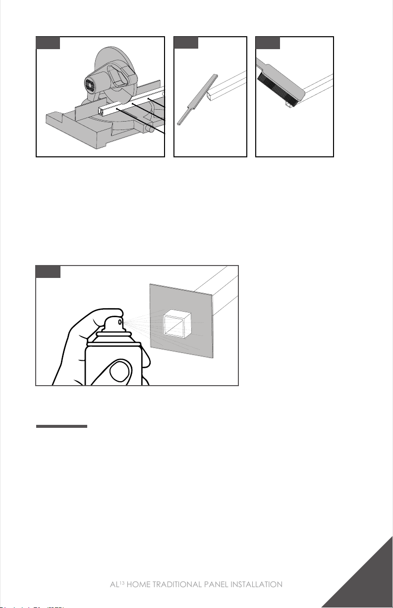
Step 2: Cut & Clean Panel
1. Cut rails using a saw with a fine tooth carbide cutting blade.
2. Use file to smooth cut edges.
3. Remove any metal shavings and dust with a brush or rag.
4. Make sure surfaces to be painted are clean.
Fig. 1 Fig. 2
Measure the panel opening
Check measurement with top
Do not measure
from post
Measure
from back
of bracket
Mark Here
Mark Here
Mark Here Mark Here
Half of Panel Length
Center of Panel
9
AL13 HOME TRADITIONAL PANEL INSTALLATION
Fig. 1 Fig. 2 Fig. 3
Step 3: Apply Spray Paint To Cut Areas
1. Using a piece of cardboard as a mask, apply the 1st coat of
Fortress zinc based touch-up paint.
2. Allow to dry before applying second coat.
3. Apply the 2nd coat of Fortress zinc based touch-up paint.
4. Allow to dry and install.
OTP INSTALLATION
Fig. 1
2X
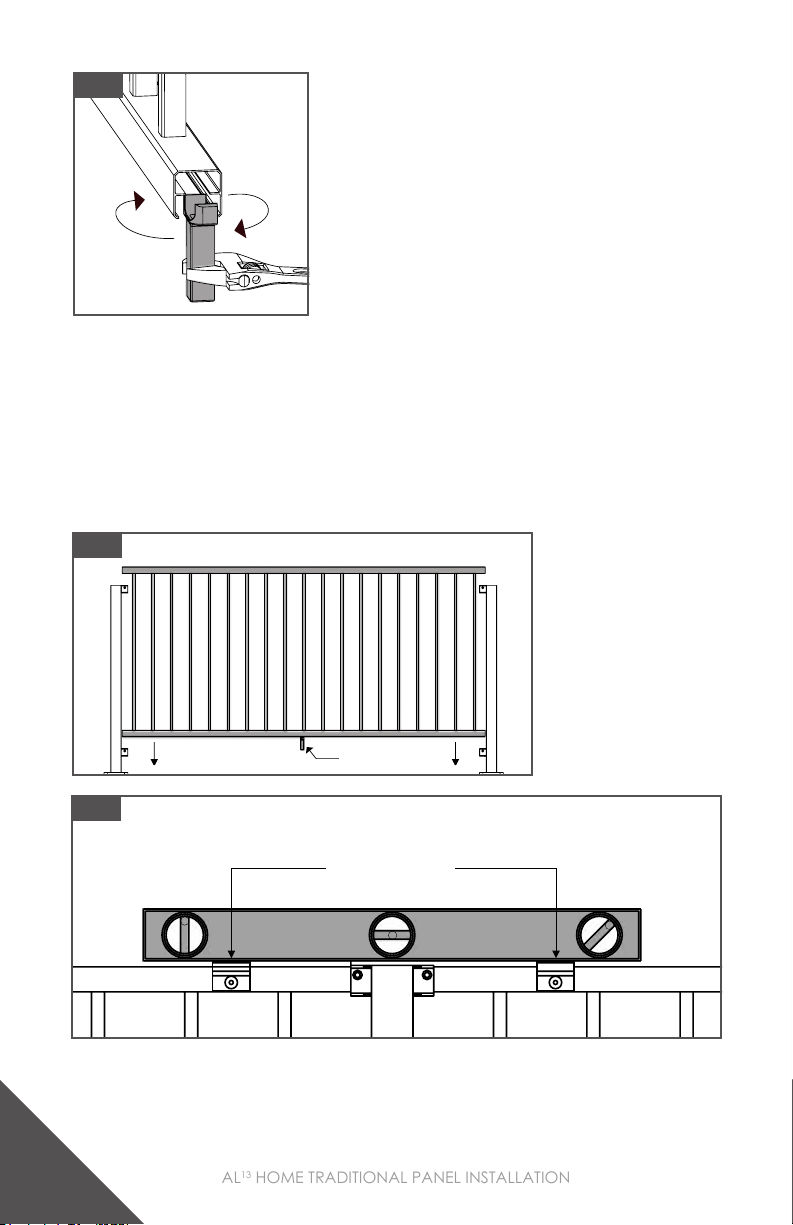
Step 1: Install I-Support On Panel
1. Install the panel I-support by twisting it into the center of the
bottom rail directly under a baluster. As shown in Fig. 1.
2. Position the I-support so the attachment screw can be easily
installed on the deck.
10
AL13 HOME TRADITIONAL PANEL INSTALLATION
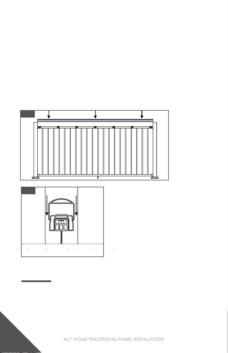
Step 2: Install Panel
1. Insert cut panel to ensure proper fit.
2. Use level to ensure that all panels are at the same height
before attaching them to the post. As shown in Fig. 2.
• The use of an ATR spacer or block might be needed to
measure over a post.
Fig. 1
Fig. 1
OTP and Proud Post: Max Post Spacing
• 8’ panel maximum post spacing is 93-7/8”.
• 6’ panel maximum post spacing is 69-7/8”.
Note: Do not exceed the maximum post spacing.
8’ Panel max post spacing 93-7/8”
6’ Panel max post spacing 69-7/8”
OTP and Proud Post: Measuring The Panel Opening Length
• Measure the distance of the panel opening.
• Measure from the back wall of the bracket to the back wall of the bracket on other post.
• Confirm that the measurements for the top brackets are the same as the bottom brackets.
Measure the panel opening
Not here
Measure from
back of bracket
Check measurement with top
3/12
I-Support
Fig. 2
ATR Spacers

11
AL13 HOME TRADITIONAL PANEL INSTALLATION
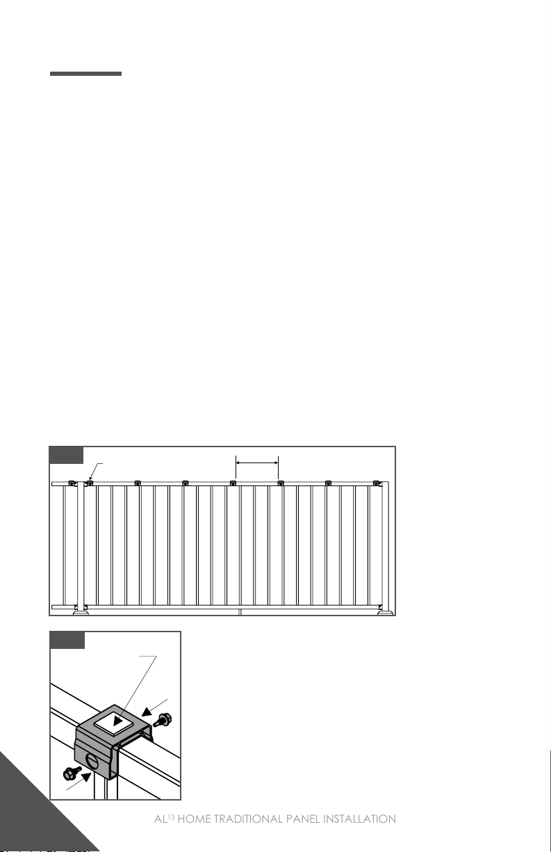
Step 3: Apply Screws
1. Attach the panel to each of the 4 brackets using the provided
self-drilling screw with a T-25 Bit.
Tip: Pre-drill with a 3/16” [4.5mm] drill bit.
Note:
• It is recommended that all panels are attached with
provided screws on the same side of the bracket
when using a line post. As shown in Fig.1.
• Only one screw is needed to secure the bracket to
the panel.
Fig. 1
Fig. 1
Step 4: Attach I-Support To Deck
1. Fasten I-Support to Deck Surface with the supplied Phillips
Head Wood Screw.
Tip: Pre-drill with a 1/16” [1.5mm] drill bit.
12
AL13 HOME TRADITIONAL PANEL INSTALLATION
OTP: ROUND ACCENT TOP RAIL (ATR)
Step 1: Round ATR Spacers
1. Attach spacers using provided self-drilling screws with a
5/16” [8mm] nut driver, two screws per spacer. As shown in
Fig. 2.
• The Accent Top Rail Kit comes with 7 spacers in the 93.89”
[2385mm] kit, 6 spacers in the 69.89” [1775mm] kit and 14
spacers in the 190” [4826mm] kit.
• The spacers should be equally spaced along the length of the
rail, with no more then 14” [279.5mm] spacing between them.
As shown in Fig. 1.
• The end spacers should be placed as close to the end brackets
as possible.
Note:
• DO NOT REMOVE BACKING OF DOUBLE SIDED TAPE
UNTIL YOU ARE READY TO PERMANENTLY ATTACH
THE ATR.
Double Sided Tape
Fig. 1
Fig. 2
Spacer Attached
Next To Bracket 14” [279.5mm]
Max

13
AL13 HOME TRADITIONAL PANEL INSTALLATION
Step 2: Round ATR Line and End Posts
1. Measure the distance from the inside edge of the 2 posts.
2. Cut the ATR to measured length.
3. The ATR cannot block the inside edge of the post. As shown in
Fig. 2.
4. When test fitting the ATR, place on top of the spacers. Do not
press the ATR down over the spacers. Removing the ATR from
the spacers can damage the ATR and spacers. As shown in
Fig. 3.
5. Remove the backing of all of the double-sided tape on the ATR
spacers.
6. A Rubber Mallet might need to be used to install. If using a
rubber mallet, use a cloth to protect the ATR from damage.
Fig. 1
Fig. 2 Fig. 3
ATR Cannot Go
Past This Line
ATR Should Go Past This
Point When Test Fitting

14
AL13 HOME TRADITIONAL PANEL INSTALLATION
Step 3: Round ATR Corner
1. When installing ATR on corners with a 2” [51mm] post, the ATR
must be 5/16” [8mm] away from the post. As shown in Fig. 1.
2. If installing a corner with a 3” [76mm] proud post, install the
ATR at full length from the inside edge of the post to the inside
edge of the post.
Fig. 1 Fig. 2
Step 4: Round ATR Splice
1. To install an ATR splice: Center the splice over the post and
with force press down over the ATR. As shown in Fig. 1,2,3.
2. A Rubber Mallet might need to be used to install. If using a
Rubber Mallet, use a cloth to protect the splice from damage.
• ATR splices reference the inside of the post and snap down
around the ATR.
• ATR splices allow up to 1/2” [12.5mm] of length variation
from the edge of the post. As shown in Fig. 4,5,6.
Fig. 1 Fig. 2 Fig. 3
CORNER LINE END
ATR With 3” [76mm] Proud Post
Over The Post
3” Post
[76mm]
ATR
ATR
ATR With 2” [51mm] Proud Post
Over The Post
2” Post
[51mm]
5/16’ [8mm]
Minimum
5/16’ [8mm]
Minimum

15
AL13 HOME TRADITIONAL PANEL INSTALLATION
Fig. 4 Fig. 5 Fig. 6
CORNER LINE END
OTP: FLAT ACCENT TOP RAIL (ATR)
Step 1: Flat ATR Spacers
1. Measure distance between brackets and cut ATR spacer to
length. The spacer can be 1/4” [6.5mm] shorter than the
distance between brackets.
2. If one of the screw holes was cut off during the sizing of the
ATR spacer, use a 5/8” [16mm] drill bit to add another hole
1” from the end of the ATR spacer.
3. Attach the ATR spacer using the provided self-drilling screws
with a 5/16” [8mm] nut driver.
4. All screw holes must have a screw installed.
Note:
• Flat ATR uses a full length ATR spacer.
• DO NOT REMOVE BACKING OF DOUBLE SIDED TAPE
UNTIL YOU ARE READY TO PERMANENTLY ATTACH
THE ATR.
1/2”
[12.5mm]
1/2”
[12.5mm]
1/2”
[12.5mm]
1/2”
[12.5mm] 1/2”
[12.5mm]
Fig. 1

16
AL13 HOME TRADITIONAL PANEL INSTALLATION
Step 2: Flat ATR Line and End
• Reference OTP Round ATR Line and End instructions on page 13.
Step 3: Flat ATR Corner
• Reference OTP Round ATR Corner instructions on page 14.
Step 4: Flat ATR Splice
• Reference OTP Round ATR Splice instructions on page 14.
OTP: CAP RAIL CLIPS & POST BASE COVER
Step 1: Cap Rail Clips
1. Install top rail bracket covers that come with the Cap Rail Clips.
As shown in Fig. 2.
2. Use Cap Rail Clips when installing a drink rail.
Note:
• Cap Rail Clips should be equally spaced over the panel length.
• It is recommended to pre-drill the screw holes.
Fig. 1 Cap Rail Clip
Double Sided
Tape
Fig. 2

17
AL13 HOME TRADITIONAL PANEL INSTALLATION
Fig. 2 Fig. 3
Step 2: Bracket Cap and Post Base Cover
1. Bracket Caps snap down over Bracket Cups.
2. Dis-assemble post base cover and install on post.
3. Use a broom or compressor to remove debris from railing and
deck surface.
Fig. 1 Fig. 2
Top Cap Installation When
Installing A Drink Rail
PROUD POST INSTALLATION
Step 1: Install I-Support On Panel
• Reference OTP I-Support Installation instructions on page 9.
Step 2: Install Panel
• Reference OTP Panel Installation instructions on page 10.

18
AL13 HOME TRADITIONAL PANEL INSTALLATION
1. Attach the panel to each of the 4 brackets using the provided
self-drilling screw with a T-25 Bit.
Tip: Pre-drill with a 3/16” [4.5mm] drill bit.
NOTE:
• Only one screw is needed to secure the bracket to
the panel.
Step 3: Apply Screws
Fig. 1
Step 5: Install Bracket Caps
1. Bracket Caps snap down over Bracket Cups.
• If you are installing a drink rail using the Cap Rail Clips, the
cap is installed under the bracket. See page16 for details.
• The top bracket cap can be installed when using an ATR but is
not required to be installed.
Fig. 2Fig. 1
Step 4: Attach I-Support To Deck
• Reference OTP I-Support Attachment instructions on page 11.

19
AL13 HOME TRADITIONAL PANEL INSTALLATION
PROUD POST: ROUND ACCENT TOP RAIL (ATR)
Step 1: Round ATR Spacers
1. Attach Spacers using provided self-drilling screws with a
5/16” [8mm] nut driver, two screws per spacer. As shown in
Fig. 2.
• The Accent Top Rail Kit comes with 7 spacers in the 93.89”
[2385mm] kit, 6 spacers in the 69.89” [1775mm] kit and 14
spacers in the 190” [4826mm] kit.
• The spacers should be equally spaced along the length of the
rail, with no more then 14” [279.5mm] spacing between them.
As shown in Fig. 1.
• The end spacers should be placed as close to the end brackets
as possible.
Note:
• DO NOT REMOVE BACKING OF DOUBLE SIDED TAPE
UNTIL YOU ARE READY TO PERMANENTLY ATTACH
THE ATR.
Fig. 1 Spacer Attached
Next To Bracket 14” [279.5mm]
Max
Double Sided Tape
Fig. 2
20
AL13 HOME TRADITIONAL PANEL INSTALLATION
Step 2: Round ATR
1. Measure the distance from the inside edge of the 2 posts.
2. Cut the ATR to measured length.
3. When test fitting the ATR, place it on top of the spacers. Do not
press the ATR down over the spacers. Removing the ATR from the
spacers can damage the ATR and spacers. As shown in Fig. 2.
4. Remove the backing of all of the double-sided tape on the
ATR spacers.
5. A Rubber Mallet might need to be used to install. If using a
Rubber Mallet, use a cloth to protect the ATR from damage.
Fig. 1
Fig. 2
ATR Should Go Past This
Point When Test Fitting
PROUD POST: FLAT ACCENT TOP RAIL (ATR)
Step 1: Flat ATR Spacers
1. Measure distance between brackets and cut ATR Spacer to
length. The Spacer can be 1/4” [6.5mm] shorter than the
distance between brackets.
Table of contents
Languages:
Other Fortress Technologies Outdoor Furnishing manuals


Popular Outdoor Furnishing manuals by other brands


Thomasville
Thomasville Richwood 203074431 Assembly instructions

Gutta
Gutta BS 160 Assembly instructions

Wisteria Lane
Wisteria Lane KX-13 instruction manual

Kettler
Kettler CUBIC 0111925-9000 Assembly & operating instructions

Canvas
Canvas SHERBROOKE 088-0095-6 Assembly instructions

Walker Edison
Walker Edison OW48PEALS Assembly instructions


