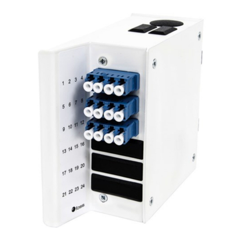
Foss FP60 User manual

MANUAL IV5016-E Issue J Page 1 of 7
fossfibreoptics.com
1. General
This manual describes installaon of pre-terminated cable, terminaon of cable using splicing and direct terminaon* of cable in panel
FP60 PRO or FP65 PRO. Some parts of the shown installaons may already be nished before delivery. If installing less bres and/or other
adapter types than shown, the manual is followed to the extent possible. When terminang less bres than the adapter plate can hold, the
rest of the holes are ed with blind plugs.
All installaon is described with the cable from the le side. If the cable should be from the right, the installaon has to be mirrored
accordingly.
It is recommended to read the whole manual once before starng the installaon.
Colour codes for cables delivered by Foss may be found under the icons to the right.
* Direct terminated cable means that the cable is prepared and the connectors assembled in the eld. The connectors may be prepolished and
without glue or meant for glue and polishing in the eld. It may also be connectors intended for direct splicing to the bre. Glue-free
connectors may be e.g. FAST or UniCam. Connectors for direct splicing to the bre may be e.g. FuseConnect.
2. Materials
Tools:
- Socket wrench 12 mm or 13 mm For use with FC or ST adapters
- Torx 25 screwdriver
- PZ2 screwdriver
- Heat gun
Addional equipment:
Depending on the applicaon the following may be necessary:
PS-3A-XHeat shrink tube, 60 mm, 100 pkn For splicing
PS-3A-X/45 Heat shrink tube, 45 mm, 100 pkn Alternave to 60 mm
4415 Cleaning kit, cables, grease For cables with loose tube
Content
1. General ...................................................................................................... 1
2. Materials.................................................................................................... 1
3.1 Alternave bracket assembly .................................................................... 2
3.2 Closing the bre guides.............................................................................. 2
4. Installing pre-terminated cable with ght buered bre.......................... 3
5. Splicing cable with ght buered bre...................................................... 4
6. Splicing cable with loose tube
A. Fibre tubes, up to 48 bres.................................................................. 5
B. Fibre tubes, over 48 bres (High Density) ........................................... 6
C. Fibre tubes, in corrugated tubes ......................................................... 6
7. Installing direct terminated cable
A. Cable with ght buered bre ............................................................ 7
B. Cable with loose tube.......................................................................... 7
Panel installaon FP60/65
Colour codes

IV5016-E Issue J Page 2 of 7
3.1 Alternave bracket assembly
The brackets are assembled as shown in picture 3.1 at delivery. This is used if
the panel is to be mounted in a 19” rack.
The bracket may be moved 2 cm forward as shown in picture 3.2. This gives
more space in front of the panel which may be benecial e.g. if the distance
to the doors in the front is very short.
When the panel is to be mounted in an ETSI (metric) rack, the brackets are
turned and assembled as shown in picture 3.3.
Aer all installaons: make sure the bre guides are closed (see picture).
3.1.1 19” assembly
3.1.2 Oset 19” assembly
3.1.3 ETSI assembly
3.2.1 Fibre guide open closed
3.2. Closing the bre guides

IV5016-E Issue J Page 3 of 7
Loosen the snap-latches and pull out the drawer.
Insert the adapters. SC adapters are inserted with the guide tracks to the
right, FC adapters with the guide tracks to the le. LC adapters are inserted
with the lock to the right.
Fasten the cable to the two foremost punched out mounts in the drawer
using e-wraps. If a second cable is used this is fastened to the backmost
mount and to the two upper holes in the rear wall as shown in picture 4.2.
Any excess cable must be handled outside of the panel.
The adapter plate may be lied up and lted to give easier access to the
adapters on the inside. See picture 4.3.
Loosen the screws on the side and li the plate up and forward (as indicated
by the arrow) unl it rest in the end of the track. There it rests while the plate
is lted to the desired angle. Tighten the screw to secure it in that posion.
Clean the adapters. Distribute the bres on the guiding crosses according to
the adapters they shall be mounted in. Clean the connectors and insert them
in the adapters.
Close the bre guides (see picture 3.2.1).
4.1 Interior of the panel
4.2 Fastening the cables
4. Installing pre-terminated cable with ght buered bre
4.4 Finished panel.
4.3 The adapter plate may be lted
2
1

IV5016-E Issue J Page 4 of 7
Prepare the cable(s) as shown in drawing 5.1.
Loosen the snap-latches and pull out the drawer.
Insert the adapters. SC adapters are inserted with the guide tracks to the
right, FC adapters with the guide tracks to the le. LC adapters are inserted
with the lock to the right. All seen from the front.
Mount a splice holder in the two mid holes as shown in drawing 5.2. It is xed
with rivets through the two holes in the middle of the holder.
Fasten the cable to the two foremost punched out mounts in the drawer
using e-wraps. If a second cable is used this is fastened to backmost mount
and to the hole in the back-wall as shown in picture 4.2.
Any excess cable must be handled outside of the panel.
The adapter plate may be lied up and turned to give easier access to the
adapters on the inside. See ch. 4.3.
Clean the adapters. If the pigtails are more than 1.5 m long, they should be
cut to this length. Clean the connectors and insert them in the adapters.
Aach splice protectors and splice the rst 12 bres, put the bres in the bre
guide crosses as shown in drawing 5.4 and place the splice protectors in the
splice holders. Fibre nr. 1 to 12 (according to front labelling) in track 1 to 12 in
the splice holder. Follow the colour coding.
Put the second splice holder on top of the rst (clipped on, turned 180°
compared to the rst). Splice and place the next 12 bres, bre 13 to 24 in
track 1 to 12 of the splice holder. Connue in the same way with the rest of
the splice holders.
Close the bre guides (see picture 3.2.1).
5.2 Interior of the panel
5.1 Cable preparaon
5. Splicing cable with ght buered bre
5.4 Finished panel.
150 cm stripped outer jacket
5.3 Fastening the cables
12
1
2
1

IV5016-E Issue J Page 5 of 7
Prepare the cable(s) as shown in drawing 6.1.
Make sure every bre is cleaned and that all grease is removed.
Loosen the snap-latches and pull out the drawer.
Insert the adapters. SC adapters are inserted with the guide tracks to the
right, FC adapters with the guide tracks to the le. LC adapters are inserted
with the lock to the right. All seen from the front.
Mount a splice holder in the two mid holes as shown in drawing 6.2. It is xed
with rivets through the two holes in the middle of the holder.
Fasten the cable to the two foremost punched out mounts and to the lower
hole in the back-wall of the drawer using e-wraps. Any excess cable must be
handled outside of the panel.
The adapter plate may be lied up and turned to give easier access to the
adapters on the inside. See ch. 4.3.
Clean the adapters. If the pigtails are more than 1.5 m long, they should be
cut to this length. Clean the connectors and insert them in the adapters.
Aach splice protectors and splice the rst 12 bres, put the bres in the bre
guide crosses as shown in drawing 5.4 and place the splice protectors in the
splice holders. Fibre nr. 1 to 12 (according to front labelling) in track 1 to 12 in
the splice holder. Follow the colour coding.
Put the second splice holder on top of the rst (clipped on, turned 180°
compared to the rst). Splice and place the next 12 bres, bre 13 to 24 in
track 1 to 12 of the splice holder. Connue in the same way with the rest of
the splice holders.
Close the bre guides (see picture 3.2.1).
6.2 Fastening of cable
6. Splicing cable with loose tube
6.1 Cable preparaon
150 cm free bre
0-1.5 cm
tube
6A. Fibre tubes, up to 48 bres
6.3 Finished panel.
12
1

IV5016-E Issue J Page 6 of 7
150 cm free bre
ca. 11 cm tube
6C. Fibre tubes, in corrugated tubes
6.7 Preparaon of cable when using corrugated tube
Strip the cable 161 cm + the length of the corrugated tube and prepare as
shown in drawing 6.7. If rubber tubes, do not ghten the e-wraps too hard.
The tubes may in this case be 19 cm outside the corrugated tube and end as in
drawing 6.8.
Protect the bre-tubes using foam tape and fasten the tubes to the two
foremost punched out mounts in the drawer using e-wraps. The foam tape
will also protect the tubes from slipping. The corrugated tube is fastened with
e-wraps to the holes in the back-wall as shown in drawing 6.8.
Then follow the instrucons in chapter 6A gure 6.3, or chapter 6B gure 6.5
depending on number of bres.
6.8 Fastening of the corrugated tube.
Prepare the cable(s) as shown in drawing 6.4. It may be benecial to await
cung the tubes unl the respecve bres are to be used.
Loosen the snap-latches and pull out the drawer.
Up to 96 bres (LC): Insert the adapters from the outside with the key to
the right.
72 bres (SC)/144 bres (LC): Insert two adapters in each hole.
Both adapter types are inserted with the keys away from each
other (one le and one right) as shown.
Mount two splice holders in the two mid holes (one for each holder) as shown
in drawing 6.5. They are xed with rivets through one of the “nut holes” at
the end of the holder (shown as black dots).
Fasten the cable to the two foremost punched out mounts and to the lower
hole in the back-wall of the drawer using e-wraps. Any excess cable must be
handled outside of the panel
The adapter plate may be lied up and turned to give easier access to the
adapters on the inside. See ch. 4.3. Clean the adapters.
IMPORTANT: If the pigtails are more than 1.2 m long, they should be cut to
this length.
Aach splice protectors and splice the rst 4 bres, put the bres in the bre
guide crosses as shown in drawing 6.6 and place the splice protectors in the
splice holders. Clean the connectors and insert them in the adapters. Follow
the colour coding.
Connue with 4 and 4 bres unl the rst splice holder is full. Put the second
splice holder on top of the rst (clipped on, turned 180° compared to the
rst). Splice and place the next 12 bres, bre 13 to 24 in track 1 to 12 of this
splice holder.
Connue in the same way unl the le stack of the splice holder have
covered half of the total bre count. Then connue with the right stack.
Close the bre guides (see picture 3.2.1).
6.5 Fastening of cable .
6.6 Finished panel.
6.4 Cable preparaon.
6B. Fibre tubes, over 48 bres (High Density)
1
1-48
or
1-72
(2)
49-96
or
73-144
48 (SC) or 96(LC)
72 (SC) or 144(LC)
1 4
5 8
1 4
150 cm
8 cm
112

IV5016-E Issue J Page 7 of 7
Foss AS
P.O. Box 3614
N-3007 Drammen
Telephone +47 32 21 08 00
Telefax +47 32 21 08 08
rmapost@foss-as.no
www.fossbreopcs.com
The informaon in this document is believed to be reliable (including drawings and pictures). However, FOSS AS makes no warranes as to its
accuracy or completeness and disclaims any liability in connecon with its use. The document may contain inaccuracies and errors. In no case
will FOSS AS be liable for any incidental, indirect or consequenal damages arising out of the sale, resale, use or misuse of the described
products. Users of FOSS AS products should make their own evaluaon to determine the suitability of each such product for the specic
applicaon. In no case will FOSS AS be liable for any errors, inaccuracies, omissions or lack of validity of informaon in this document.
Any use or copying of this document for other purposes than it is intended is strictly forbidden.
Prepare the cable(s) as shown in drawing 5.1.
Connectors for direct terminaon (e.g. FAST, UniCam, FuseConnect) are
assembled according to the instrucons from the supplier.
Then follow the instrucons in chapter 4, gure 4.1 and onwards.
Prepare the cable(s) as shown in drawing 6.1.
Make sure every bre is cleaned and that all grease is removed.
Connectors for direct terminaon (e.g. FAST, UniCam, FuseConnect) are
assembled according to the instrucons from the supplier.
Then follow the instrucons in chapter 6A, gure 6.2 but do NOT install the
splice holder.
The adapter plate may be lied up and turned to give easier access to the
adapters on the inside. See ch. 4.3.
Clean the adapters. Distribute the bres on the guiding crosses according to
the adapters they shall be mounted in. Clean the connectors and insert them
in the adapters.
Close the bre guides (see picture 3.2.1).
7.2 Finished panel
7. Installing direct terminated cable
Direct terminaon may be used on several cable types. In the following cable with ght buered bre and loos tube cable are covered.
7.1 Finished panel
7A. Cable with ght buered bre
7B. Cable with loose tube
7.1 Finished panel
This manual suits for next models
1
Table of contents
Other Foss Cables And Connectors manuals
