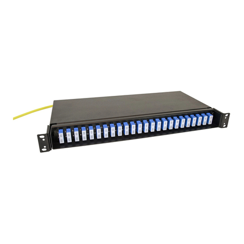
Foss FPD66 User manual

IV5038-E Edion B fossbreopcs.com Page 1 of 3
Installaon guide
1. In general
This guide shows how to splice cables with pigtails in the DIN closure FPD66. Parts of the installaon may be made by FOSS prior to delivery.
This closure may be used for up to 12 splices against pigtails. However; by factory terminated cables or direct terminaon, the closure may
hold 24 bres using the LC Quad adapter. If less bres than a full adapter front is used, the rest of the holes should be blinded using blind
plugs. This guide shows installaon with adapters poinng le (if a wall mount bracket is used), but the closure may be used poinng right. In
such a case, think mirrored when reading this manual.
You are advised to read through the full installaon guide upon beginning the installaon.
Colour codes for cables delivered by FOSS may be found under the QR code/link on the right.
2. Materials
Depending on the type of installaon and/or cable, the following may come to use:
PS-3A-X/45 Splice protector, 45 mm, 100 pack
4415 Cleaning kit, grease For loose tube cables
317-10600 Crimp sleeve 6/2
For addional equipment for the closure itself, see data sheet. Link to the right
Contents
1. In general................................................................................................... 1
2. Materials.................................................................................................... 1
3. Splicing pigtails .......................................................................................... 2
4. Mounng to DIN rail/wall box/raceway .................................................... 3
Splicing in FPD66
Data sheet
Fargekoder
Colour codes

IV5038-E Edion B fossbreopcs.com Page 2 of 3
3. Splicing pigtails
Prepare the cable according to one of the drawings in 3.1. If you need longer
bre ends, add 33 cm for an extra loop. If direct terminaon, use 70 cm for all
bres
Tight buered cables
Loose tube cables
3.2
3.3
3.4
3.1
M20
M20
85 cm
(fibres 7-12)
70 cm
(fibres 1-6)
82 cm
(fibres 7-12)
67 cm
(fibres 1-6)
3 cm
3 cm
3 cm
Cut pigtails to lengths 70 cm (bres 1-6) and 85 cm (bres 7-12).
Splice one bre at a me, coil and mount them to the splice holder. Fibres
1-6 is mounted according to leer A and the red bre on the drawing, bres
7-12 is coiled half a turn more before mounng to splice holder. All coiling is
made in the same direcon (counter-clockwise) to ensure proper bend radii.
Make connectors point out through the back (underneath the entering cable)
on the last turn and connect them to the adapter front there.
When all bres are spliced, turn the adapter front around to the front and
aach it to the closure (B). Push it in from the front so that the bre clamp
also is pushed in. Insert blind plugs in all unused holes. Raise the p of the
rear bre clamp (C) and mount the lid/back wall.
Detach the lid/back wall using a Torx 10 screwdriver.
Put on the appropriate numbering tab (depends on type of adapter), see
drawing 3.2. Install adapters.
Detach the adapter front and put it aside.
A
A
B
C
C
A
A
BCC
Install bre guides (A), splice holder (B)
and bre clamps (C).
Put the le bre clamp parally under
the low sloping wall.
If cable diameter is below 5 mm, increase the diameter using crimp sleeve(s)
of 7 cm length (placed so it ends up inside the cable gland)
Put the cable through the cable gland, the strain relief unit and the nut, and
mount together. Secure the cable using e-wraps.
3.5
A
C
B

IV5038-E Edion B fossbreopcs.com Page 3 of 3
Foss AS
P.O. Box 3614
N-3007 Drammen
Telephone +47 32 21 08 00
Telefax +47 32 21 08 08
rmapost@foss-as.no
www.fossbreopcs.com
The informaon in this document is believed to be reliable (including drawings and pictures). However, FOSS AS makes no warranes as to its
accuracy or completeness and disclaims any liability in connecon with its use. The document may contain inaccuracies and errors. In no case
will FOSS AS be liable for any incidental, indirect or consequenal damages arising out of the sale, resale, use or misuse of the described
products. Users of FOSS AS products should make their own evaluaon to determine the suitability of each such product for the specic
applicaon. In no case will FOSS AS be liable for any errors, inaccuracies, omissions or lack of validity of informaon in this document.
Any use or copying of this document for other purposes than it is intended is strictly forbidden.
Onto DIN rail:
The base units DIN-clip is clipped on boom rst. The box is then pulled up to
clip on to the top part of the rail.
The DIN clip is mounted at the rear on delivery (le picture).
If you want to have the clip on the at side of the box, a wall bracket must be
used (must be bought as accessory, see data sheet DB4177):
This is xed to the box with the same screws/holes as was used for the
DIN-clip. Then the DIN-clip is xed to the bracket with 3 pcs. Of M3 screws.
Note that the spring loaded side of the clip should point downwards. (Closure
facing right; mount clip upside down)
Onto a wall, in front of a wall box or onto a raceway front:
To mount directly to the wall the DIN-clip is replaced by a wall bracket (may
be bought as accessory). This is xed to the box with the same screws/holes
as was used for the DIN-clip. The screws are inserted into the wall with 60 cm
distance and the bracket is hooked on using the key-holes, the slots are 4.5
mm wide. (The easiest may be to use the bracket as a template when making
the holes in the wall).
If the box needs to be secured hard to the wall, the bracket may be xed to
the wall rst and the box mounted on the bracket aerwards (but then the
box may not be placed in a corner).
The bracket is also used if the closure is to be put in front of a wall or raceway
box. (Box has to have its screws c/c 60 mm horizontally.)
In this case, mount the bracket to the wall box rst, then the closure to the
bracket. Cable should be put through the bracket hole, down and into the
closure. (Max cable diameter 7 mm). Assure that cable’s minimum bend
radius is not violated.
The lid may be removed even though the closure is aached to the bracket:
Remove the 4 screws, then slide the closure out, sideways or upwards.
4.1
4. Mounng to DIN-rail/wall box/raceway
4.2
4.3
Table of contents
Other Foss Cables And Connectors manuals
Popular Cables And Connectors manuals by other brands
CORNING
CORNING SST Installing a Wire Mesh Pulling Grip
Staubli
Staubli CombiTac MA213-09 Assembly instructions
Philips
Philips SWV4422S/10 user manual
STODIA
STODIA 22103057 operating manual

Kindermann
Kindermann CablePort desk2 80 turn Mounting instructions

Flash butrym
Flash butrym DMX SPLITTER 8 User's manual & operating instructions
