Fostex 812 User manual
Owner’s
Manual
Model
RECORDING
MIXER
F05CGX
A
A
RISK
OF
ELECIHIC
SHOCK
OO
NOT
OPEN
CAUTICN:
TO
REDUCE
THE
RISK
OF
ELECTRIC
SHOCK.
CO
NOT
REMOVE
COVERlOR
BACK).
NO
USER-SERVICEABLE
PARTS
INSIDE.
REFER
SERVICING
TO
QUALFIED
SERVICE
PERSONNEL.
A
The
light
ring
llasti
with
arrowhead
symbol,
/f\
within
an
equilafero
triangle,
is
mended
to
/V
alert
tho
iser
lo
lhe
prese-xre
of
uninsulated
/
J
\
"dcngerous
voltage’
within
the
Deduct
s
en-
/
V
\
closure
that
rray
be
ol
sullicieni
magnitude
lo
corstitutea
risk
ol
electric
shock
to
person*.
A
The
exclamation
point
vviihri
an
equilateral
/«\
Iriaoyte
Is
intended
lo
ubrl
the
user
u
lire
/
I
\
f/esenco
ol
imports!
ni
opening
and
mninie-
/
I
\
nance
(sarveing)
instructions
in
the
literature
/
*
\
accompany
ng
the
appliance
'WARNING"
TO
REDUCE
THE
RISK
OF
FIRE
OR
ELECTRIC
SHOCK.
LO
NO
l
bXHUSt
I
HIS
AmiANCt:
10
RAIN
0RMQI5-
Tunc."
SAFETY
INSTRUCTIONS
1.
R;ad
Instructions
Al
the
oafcl/
and
operating
inolrvc
twins
shm
ild
he
r«»ri
bolore
lhe
appliance
is
operatnd
?.
Ftetain
inslruchnns
-Tie
salety
and
occiaiina
instructions
should
be
relaned
lo
lulure
reference.
3.
Heed
Warnings
-
All
warnngs
or
the
applianceand
in
the
operating
mstruenons
should
be
acnereo
io.
4.
Follow
Instructions
—
All
jperatny
anc
uie
instructions
choiJd
ho
lollowod.
Ft.
V*tio»
and
Moisture
-
The
appliance
should
not
b?
used
near
water
-
ler
example,
near
a
bathtub,
washbowl,
kit-
cher
sirk,
laundry
:ub,
in
s
wet
basement,
or
near
a
swim¬
ming
pool,
and
the
like.
6.
Carts
arvd
Sturds
Tho
appimrco
should
bo
used
only
with
a
cart
or
stand
that
is
recommended
by
the
mami:
lacturei
An
appfianco
anc
cert
combination
should
t>e
moved
with
care.
Quick
stops,
excessive
force
and
uneven
surlace3
nay
cause
tno
appiarce
and
cart
combiriaioi
t5
overturn.
7
Wull
or
Guiltly
Mounting
—Tlic
upoliaivsc
olxxitd
be
muml-
td
to
a
wal
or
coilivj
only
ic
ronnmmnnrtoil
hy
Hip
mrnu-
(acturer
8
YGniiation
-
Tie
appiaixe
should
be
mtuatec
so
that
its
locaiioncr
costion
does
not
nte-iere
win
is
proper
venti¬
lation.
For
example.
Ihc
ooplanco
cncUd
not
bo
eitualoc
on
a
bed.
sofa
ruo.
ct
similar
surface
Inal
mav
blxck
the
venlilation
openings;
or,
placed
in
a
built-in
nstalla»on
such
as
a
bookcase
or
cabinet
lhat
may
impede
the
rio//
o’
air
tnrough
the
ventilation
openings.
9.
Hc&l
The
appliance
ohould
bs
silualod
away
Irom
host
sources
such
as
rarintors.
heat
recsle
s,
staves.
cr
olhei
appiances
(including
amplriiers)
that
txoducs
heat.
10.
bovver
Sou-cos
■
rhcopplanccshculdbeccrnecteotOE
cower
supoly
only
of
the
type
assenbeO
m
me
operating
nolfii
clone
or
no
marked
on
ho
appianco
It.
GramdinQorPolarizaticn
-
Theprecaulwnsthatshould
oe
la
ken
so
that
live
grounding
or
polarization
means
d
an
appiiarce
s
not
defeated
12.
Rwer
Cord
Hotectiai
-
Riwer
supply
cords
should
be
routed
so
thal
Ihey
are
nc*
likely
to
be
wdked
on
cr
pinohod
by
items
pticed
ipon
or
against
them,
paying
particular
aitention
to
cords
at
plugs,
convenience
recep-
lades,
ana
the
point
whore
they
exit
from
the
appliance.
13.
Cleaning
-
The
appliance
should
bo
ebaned
only
as
recommended
by
the
manufacturer.
l
X
Ncr
use
Periods
-
The
powo
ccrd
cl
theappiianco
should
be
unpuggod
from
tho
cutlet
vision
loft
unused
lor
along
period
of
time.
IS
Ohjncl
and
I
iquid
Entry
-
Care
should
te
taken
so
lhat
obiectsdonoi
tall
and
licuicts
are
not
suited
into
the
enc¬
losure
through
openings.
16.
Damage
Requiring
Service
-
The
appliance
should
be
serviced
Py
qualllled
service
personnel
when:
A.
The
power
supply
cord
or
the
plixj
has
been
damaged;
or
8.
Cbiecls
have
fatten,
cr
licuid
has
been
spiled
into
the
appliance;
or
C.
The
appliance
has
been
exposed
to
rain;
or
D.
lhe
appliance
does
roi
appear»
operate
normaly
cr
exhbils
a
marked
change
n
performance;
c*
E.
The
appliance
hse
boon
dropped,
or
the
onciceuro
damaged
17
Servicing
-
The
user
should
tut
attemul
lo
service
the
appliance
beyond
that
described
in
the
opora&ng
instruc¬
tions.
All
ether
servicing
should
be
referred
to
qualified
service
personnel.

INTRODUCTION
Thank
\ou
very
much
for
purchasing
a
Fostex
Model
812
Recording
Mixer.
The
Mode
B12
is
a
'2-inpul
'eoording
mixer
with
al
the
necessary
functions
required
fo
a
multilracK
recording.
Tiie
Model
G12
has
all
of
the
foltowing
features
1
An
8
channel
output,
orcvicina
the
pcrlcct
combination
wifi
an
8-track
multitrack
recorder.
2
Two
Effect
Sends
(monaural)
and
ar
Auxilary
Send
(stereo),
al
owing
a
variety
of
sound
effect
processes
possible
3.
The
capability
to
send
the
AUX
signal
(while
monitoring
the
recorder
output
signal)
to
the
Effect
Send
2
output,
making
it
possibe
to,
tor
example,
cas
a
reverceraton
or
this
signal
and
thus
slmuiaie
the
recording
environ¬
ment
wiliout
tampering
with
lire
output
sigials
to
the
recorder
4.
Two
paranetic
and
cne
shelwng
ec
utilizers,
giving
more
flexibility
to
tone
control,
and,
with
the
use
of
a
solo
moni¬
tor
‘unction
and
.mute
furction.
the
mixing
process
is
made
even
more
easy.
5.
Three
stereo
Effect
Returns
alowing
connections
vari¬
ous
sound
effect
processors
without
sacrificing
irput
channels
lo
eccept
the
output
signals
from
the
piocessors
6.
A
DC24V
phaniom
power
source,
enabling
-lookup
to
e
high
quality
condenser
microphone
7.
An
FL
level
merer.
8.
Space
fer
connectng
MID!
interfacing
:
or
future
use
with
MIDI
control.
We
hepe
that
you
tnoroughiy
-ead
this
Manjal
and
wil
utilize
(he
product
to
its
fullest
capabilues.
With
proper
use
and
maintenance,
you
wil
enjey
maiy
years
ol
satisliec
periornance.
TABLE
OF
CONTENTS
■
M
IWhh.
SECTION
1
V
■
W
W
I
1
I
lall
|
SPECIFICATIONS
PAGE
2
SECTION
8
M
JUITRACK
RECORDING
PAGE
12
SECTION
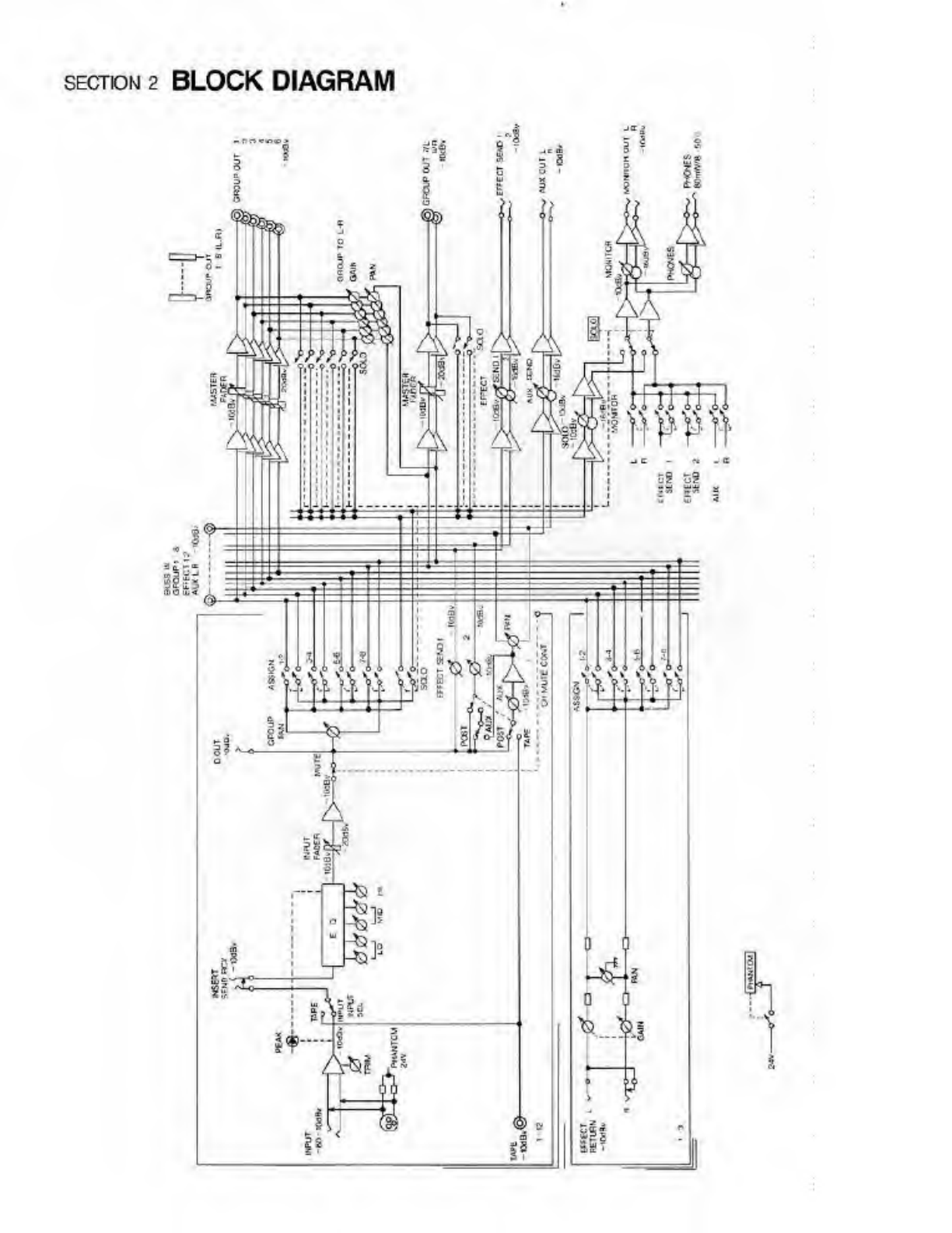
2
BLOCK
DIAGRAMS
3
SAMPLE
CONFIGURATIONS
12
SECTION
3
GUIDE
TO
COMPONENTS
5
BASIC
TRACK
RECORDING
12
SECTION
4
THE
PARAMETRIC
EQUALIZER
9
OVER-CUBBING
14
SECTION
5
CONNECTING
FFFFCTORS
9
PING-PONG
RECORDING
15
SECTION
6
CONNECTING
PERPHERAL
10
M
XING-DOWN
16
SECTION
7
EQUIPMENT
BASIC
SIGNAL
FLOW
11
SECTION
9
TROUB_E-SHOOTING
19
section
i
SPECIFICATIONS
INrUT
(A
12)
AUX
OUTPUT
|L/R)
<>
1)
Mlcrophonn
Impedancr
WOE
or
less
Output
lead
impedance
lOkO
cr
mere
Input
Imoe
dance
?M)
balanced
X.R
connector
Nominal
output
leva
-IOcBV
(0.3'/)
ana
20
hQ
unDnOnecrl
pl-varc
HCk
Maximum
output
level
MONITOR
OUTPUT
(LR)
|x1)
Output
load
impedance
•ilOdSV
iSGY)
Ncmnal
Input
level
Microp*>one
603
BV
[imV.
lOkO
Jr
mere
Line:
lOdDV
(-5.3VI
Nominal
output
lev©
-1000V
103'/)
Minimum
Input
level
70JBV
(OlnW)
Maximum
output
level
-iSdBV
S6V)
Maximum
input
level
Hbdt5V(5CV}
HEADPHONES
OUTPUT
(Stereo)
TAPE
INPUT
(-
12)
Output
load
Imparlance
8-5CU
Input
impedance
Mkt!
Maximum
output
BCmVY
Nominal
Input
level
-IUCIUV(OSV)
DIRECT
OUTPUT
(X
12)
Minimum
Input
level
2COBV
(O.'V)
Output
load
Impsdanco
lOkll
V
nao
Maximum
input
level
t-l5dBV(5.6V)
Nominal
output
leva
-IOoBV
(03
V)
INSERT
INPUT
(X12)
Maximum
output
level
-tStlBV
i.sev)
Input
impedance
JOktl
FREQUENCY
RESPONSE
Nominal
input
level
-
lOdBV
(05V)
Mcrophone
input
20
-
20kH2
.1/-20B
INSERT
OUTPUT
(X12)
Line
input
20-?0kHz
-.V-1CI0
Output
load
impedance
'Old?
or
moia
Monitor
rxilput
30-20kH7
il/—3dR
Nominal
output
level
-
10QBV
(Q3V)
Headphones
output
20
-
20kHz
.1/-20B
Maximum
output
level
►
I30BV
(0.0/)
EQUIVALENT
INPUT
NOISE
—12SQBV
w&gnteo
BUSS
INPUT
iGROUPxB,
EFFECT
*2,
AUX
(Lfl)xl)
OVERALL
SIGNAL
TO
NOISF
Input
impotbnce
20
kl)
1
mlc
input
6£el8
weghlcd
Nominal
InpJt
level
-
IOUBV
(03V)
(2
mlc
Input
wegrweo
EFFECT
RETURN
(UR)
(<3)
T.H.D.
0.115%
(UHz.
nominal
ln«=l)
Input
impedance
7kQ
0.1%
(heaGphunis
1kHz
Nominal
Input
level
lOJOV
(O.CV|
lOnMWXW)
Maximum
input
level
+2SdBV
(173V)
FADER
ATTENUATION
7Cd3
(1kHz)
GROUP
OUTPUT
(x
6)
CROSSTALK
6£d8
(1kHz)
Output
lood
Impcflcncc
OHO
or
mere
PARAMETRIC
EQUALIZER
00-
HI?
ti3d0
Nomnal
output
level
-
10.1BV
(03V)
400-6kHz
*I5
cB
Maximum
output
level
»15dBV
(5.6V)
10kH:
*i5d8
(SHEIVIM3)
EFFECT
SEND
(x2)
POWER
REQUIREMENTS
100V
42W
Cut
put
load
impedance
•QkQ
cr
more
120V
4EW
Nomnal
output
level
WdBV
(03V)
220V
4£W
Maximum
output
lovcl
*
tSoBV
(&.6V)
DIMENSIONS
(HxWxD)
2‘0V
4EW
175
mm
x
$70rm
x
530mm
WEIGHT
1*9129
lt«S)
PHANTOM
POWER
SLPPLV
DC34V
EF<FC1
1
3


SECTION
3
GUIDE
TO
COMPONENTS
4
The
numbers
in
()
indicate
the
bcaticn
of
tie
component.
FRONT
PANEL
1.
PEAK
LED
This
LED
turns
on
when
the
input
signal
to
INPUT
jacks
(35)
and
(36)
or
to
Hie
TAPE
IN
jack
(36)
is
overloaded
(+
13dB).
if
the
LCD
tends
to
turn
on
frequently,
adjust
the
TRIM
(2)
or
tho
EQUALIZER
GAIN
(-1)
unti
an
appropriate
level
is
reached.
For
details,
refer
to
pa.
ADJUSTING
IN¬
PUT/OUTPUT
LEVELS.
2.
INPUT
TRIM
This
krob
trims
the
pro
amplifier
gain
ci
the
incoming
sig¬
nal
Irom
INPUT
jacks
(35)
and
(36).
The
TRIM
responds
to
a
wide
range
from
-60dBV
(microphone
level)
to
-
ICdEV
(line
level)
Please
note
that
the
input
eve!
horn
the
TAPE
IN
jack
(38)
can
net
be
adjusted.
a
INPUT
SELECTOR
(INPUT/TAPE)
This
selects
the
signal
to
be
sent
to
toe
INPUT
FADER
(15).
INPUT<
I):
The
sound
source
coming
irro
INPUT
jacks
(35)
and
(36)
is
selected
(Used
mainly
when
record¬
ing).
TAPE(
-
):
The
scxino
source
coming
into
TAPE
IN
jack
(33)
6
selected
(Used
mainly
when
mixing
down).
4.
EQUALIZER
SECTION
This
section
adpsts
the
tone
quality
of
the
sound
signal
selected
hy
the
INPUT
SELECTOR
(3)
Fcr
further
details,
refer
to
pg.
r
HE
PARAMETRIC
ECUALIZER.
5.
EFFECT
SEND
1
This
knob
aejusts
the
output
level
of
tho
pcst-FADER
sig¬
nal
(the
signal
after
adjusted
by
INPUT
FADER
(15))
before
being
sen:
to
the
EFFECT
SEND
1
buss.
Tne
signal
is
sen
to
the
EFFECT
SEND
1
buss
via
the
SEND
1
MASTER
LEVEL
knob
(21)
and
is
culputted
from
tie
EFFECT
SEND
1
jack
(5G)
and
may
be
sent
to
effectors
for
processing.
6.
EFFECT
SEND
2
SELECTOR
(AUX/POST)
This
selector
is
effective
only
when
the
AJX
SELECTOR
(8)
is
set
to
TAPE
(is.
is
depressed),
it
sslects
the
signal
to
be
sent
to
EFFECT
SEND
2
(7).
3
CST(I):
The
post-
FADER
sgnal
is
selected.
AUX(«):
The
signal
from
the
TAPE
IN
jack
(38)
alter
being
adjusted
by
AUX
GAIN
(9)
is
selected.
Note
that
when
:he
AUX
SE_ECTOR
(8)
is
set
to
POST
Hus
sclecto-
has
no
eTect
anC
thus
the
signal
sent
to
the
EFFECT
SEND
2
(7)
will
bo
POST
7.
EFFECT
SEND
2
Inis
knot
adjusts
the
outout
level
of
the
signal
being
sent
to
Ihe
EFFECT
SEND
2
buss.
From
hu
e
the
signd
then
is
sent
to
the
SEND
2
MASTER
LEVEL
knob
[22)
and
outputted
from
tne
EFFECT
SEND
2
jack
(49)
and
used
for
effect
processing.
a
AUX
INPUT
SELECTOR
(POST/TAPE)
Tins
selects
'.fie
signal
to
be
sent
to
the
AUX
GAIN
(9).
POST(l.):
Tho
post
FADER
signal
is
oaloctcd.
TAPE(-):
Tine
incoming
signal
to
tne
TAPE
IN
jack
(38)
is
selected.
Usually,
if
one
warts
rt
process
an
effect
usng
the
posf-
FADER
signal
via
the
AUX
GAIN
(9).
POST
is
selected
If
one
wants
to
monitor
the
output
from
the
recorder
while
mixing-down.
TAPE
is
selected.
9.
AUX
GAIN
A
This
knob
adjusts
tne
level
of
the
sicmal
selected
by
the
AUX
SE.ECTOR
(8)
and
sent
to
the
AUX
buss.
The
func¬
tion
of
tnis
krob
varies
depending
on
the
status
of
the
AUX
SELECTOR
(8).
FOST:
serves
as
a
stereo
itpu:
type
EFFECT
SEND.
TAPE,
selves
as
a
monitor
volume
control
cf
the
recorder
output
coming
intoTA^E
IN
jack
(30).
The
signal
which
is
sent
to
tho
AUX
buss
passos
through
tho
AUX
MASTER
LEVEL
knob
(23)
ard
is
outputted
from
the
48.
AUX
OUT
jack
and
nay
ha
used
as
an
input
signal
to*
stereo-input
effectas.
10.
AUX
PAN
This
pan
adjusts
the
Left-Right
balance
of
the
signal
be¬
ing
serf
to
the
AUX
hiss
from
AUX
GAIN
(9)
When
the
AUX
SELECTOR
(3)
s
in
the
POST
position,
it
may
be
used
for
setting
the
L-R
baiarce
for
the
EFFECT
SEND
signal.
When
in
the
TAPE
position,
it
may
be
used
for
setting
the
perspective
of
the
record©
output
monitor
g
signal.
11.
GROUP
ASSIGN
SWITCHES
These
switches
{alorg
with
GROUP
PAN
(12))
assign
ihe
signal
sent
!
rom
the
INPUT
FADER
(15)
to
GROUP
busses
1
-8
-
GROUP
ASSIGNING
depressed=ON
'[H
:
Button
down
:
Eulton
up
)
to
GROUP
buss
1
U
1-2
I
13-4
□
«
O’
P*N
CCO
EV?N
to
GROUP
buss
!>J
:<-4
□
«
rtu
:<?
ODD
EVEN
to
GFfOUP
busses
-o
GROUP
busses
5
&
6
at
Ihe
same
level
1
~8
at
the
same
level
4
PAN
n«
[Vfifl
i.
•»
I
I
»•»
OTO
EVEN
I
'-2
I
I
9-0
I'.a
PAN
OCC
EVEN
12.
G
ROUP
PAN
Along
with
he
GRCUP
ASSIGN
SWTCHES
(11).
the
assigning
is
done
as
illustrated.
4

13.
INPUT
SOLO
SWITCH
When
ths
switch
is
pressed
(ON),
Ihe
SOLO
LED
(33)
is
turned
on
snd
the
post-FADER
signal
ol
that
channel
is
sent
to
the
SCLO
buss
The
MONITOR
SELECTOR
(25)
s
overridden
and
the
SOLO
buss
output
signal
is
sent
:o
both
me
MONITOR
LEVEL
kncb
(26)
and
PHONES
VOLUME
{27).
in
other
words,
the
pcsi-FADER
signal
ol
the
partcuar
channel
can
now
be
monitored
using
ncadphcncs
or
speakers
T-ic
montored
signal
main
tains
lie
perspective
set
with
the
PAM
pot
(12),
making
equalczirg
adjustments
with
FOUAII7FR
(4)
possible
without
anv
sound
distortion,
"his
feature
affects
only
the
signals
sent
to
the
MONITOR
OUT
jack
(47)
and
PHONES
jack
(34).
14.
MUTE
SWITCH
When
ths
switch
is
oressed,
the
LEC
located
within
the
swteh
vvll
toggle
between
ON
and
OFF
When
the
LED
is
ON.
the
signal
entering
the
INPUT
FADER
(15)
ol
that
channel
wll
be
rruted.
This
Is
the
equivalent
ol
complete¬
ly
lowering
the
INPUT
FADER
and
is
useful
when
one
wants
to
cut
out
a
chanrel
without
moving
the
FADER
position.
Whan
Iho
LED
is
OFF,
the
nuto
function
c
releasee
15.
INPUT
FADER
Ths
adjusts
ihe
level
of
the
sgnal
selected
by
the
INPUT
SELECTOR
(3).
As
roise
and
distortion
is
minimum
at
the
scale
range
of
0
*
5idR),
if
is
recommended
to
initially
set
the
INPUT
"ADER
within
this
range
and
then
adjust
with
TRIM
(2).
16.
GROUP
MASTER
FADERS
(busses
1
-6)
These
a
r
e
the
master
farters
for
GROUP
busses
1
respectively.
Not
ony
are
the
cutout
signal
levels
to
the
GROUP
OJT
jacks
(45)
adjusted
here,
but
also
signal
levels
to
the
GROU=*
TO
L-R
SECTION
(18)
and
(19)
es
well.
Normally
this
area
is
used
io
set
the
sgnal
level
OJ
the
outpjt
:o
TRACKS
1
-6
ot
a
multitrack
recader.
17.
GROUP
MASTER
FADERS
(busses
7/L,
8fR)
These
two
are
the
master
teders
for
GROUP
busses
7
and
8.
The/
adjust
the
signal
leves
assigned
directly
to
GROUP
busses
T
and
8
from
GROUP
ASSIGN
(11)
and
(12))
es
well
as
signel
levels
assigned
via
the
CROUP
TO
L-R
SECTION
(16)
end
(19).
Normally
thccc
arc
used
lo
so:
Iho
signal
leva!
of
the
output
to
TRACKS
7
and
8
of
a
mutitrack
renoide'
Also,
wnen
mixing-down,
they
may
be
used
lo-
signal
leve
adjustment
tc
a
master
recorder
(ie
fer
lade-intout
purposes).
18.
GROUP
TO
L-R
GAIN
These
knebs
adjust
the
individual
levels
d
GROUP
busses
1-6
when
assigning
them
to
GROUP
busses
7
and
&
For
examole.
in
a
mixing-down
situation
Une
source
signals
may
be
assigned
to
GROUP
busses
1-6.
men
collectively
sen:
to
CROUP
busses
7
and
8
after
ueny
adjusted
at
the
GROUP
TO
L-R
SECTION
(1C)
end
(19)
and
finally
outputted
to
a
master
reccrder.
19.
GROUP
TO
L-R
PAN
Ihese
knoos
ad|ust
me
Lett-Right
perspective
of
the
signas
o
be
sent
io
GROUP
busses
7
aid
B
A
turn
towards
L
will
send
the
signal
towards
GFOUP
buss
7
while
R
will
send
the
signal
towards
GROUP
ouss
3.
After
bene
assigned
to
GROLP
busses
7
and
8
from
here,
the
signals
are
then
outputted
from
GROUP
OUT
jacks
7/L
and
8
R
1461
via
GROUP
MASTER
RADERS
7/L.
S
(17).
20.
GROUP
SOLO
SWITCH
When
this
swteh
is
pressed,
Ihe
respective
GROUP
duss
outoul
signal
is
sent
to
the
SOLD
buss.
Similar
to
:he
INPUT
SOLO
SWITCH,
the
MONITOR
SELECTOR
(25)
isoverrdden
and
the
signal
sent
to
both
the
MONI¬
TOR
OUT
jack
(47)
and
the
PHONES
jack
(24).
erabmg
monitor!
rg
with
head
phones
or
speakers.
21.
EFFECT
SEND
1
MASTER
LEVEL
KNOB
71
iis
knob
adjusts
Ihe
master
level
of
the
signds
sent
to
the
EFFECT
SEND
1
busa
which
is
then
outputted
from
Ihe
50.
EFFECT
SEND
1
jack.
22.
EFFECT
SEND
2
MASTER
LEVEL
KNOB
This
knob
adjusts
the
master
level
of
the
signers
sent
to
the
EFFECT
SEND
2
buss,
which
is
then
outputted
from
the
49.
EFFECT
SEND
2
jack.
23.
AUX
SEND
MASTER
LEVEL
KNOB
Tins
knob
adjusts
the
master
level
of
ihe
signets
sent
to
the
AUX
buss.
which
ic
then
outputted
from
the
48.
AUX
OUT
jack.
24.
SOLO
LEVEL
KNOB
This
knob
adjusts
IIie
master
tevd
cf
lire
siyiab
sent
to
the
SOLO
buss,
which
ncudes
sicnal3
coming
from
NPU~
SOLO
switches
and
GROUP
SOLO
switenes.
25.
MONITOR
SELECTOR
This
selects
the
signal
to
be
sent
to
MONITOR
OLT
jack
(47)
and
PHONES
jack
(34).
L-R:
The
output
signal
from
GROUP
busses
7
and
8.
AUX:
The
output
signal
from
he
AUX
buss
(ie
tc
be
outputted
from
the
AUX
OUT
ack
(48)).
EFFECT
SEND
1:
The
signal
to
be
outputted
‘rom
the
EFFECT
SEND
I
jack
(50)
is
selected
with
a
central
perspective
EFFECT
SEND
2
The
signal
to
be
outputted
Iron
the
EFFECT
SEND
2
jack
(49)
is
selected
with
a
central
perspective
n
general.
L-R
is
used
when
mixing-ctown.
AUX
is
used
whan
monitoring
Ihe
output
to
a
recorder.
The
selection
is
made
when
the
respective
switch
is
depressed.
26.
MONITOR
LEVEL
KNOB
This
knob
adjusts
the
output
leve
of
the
signal
sen!
to
the
MONITOR
OUT
jack
(47).
27.
PHONES
VOLUME
This
controls
the
volume
of
the
signal
sent
to
the
34.
PHONES
jack.
28.
EFFECT
RETURN
1
SECTION
I
his
section
assigns
the
signal
coming
into
EFFECT
RTN
1
jacks
(40)
to
GROUP
busses
t
-£
The
assigned
buss(es)
is
determined
by
the
use
cf
the
RTN
1
ASSIGN
SWITCHES
(28)
and
Ihe
RTN
1
PAN
(28).
The
signal
leve
is
adjusted
by
RTN
1
GAIN
(28)
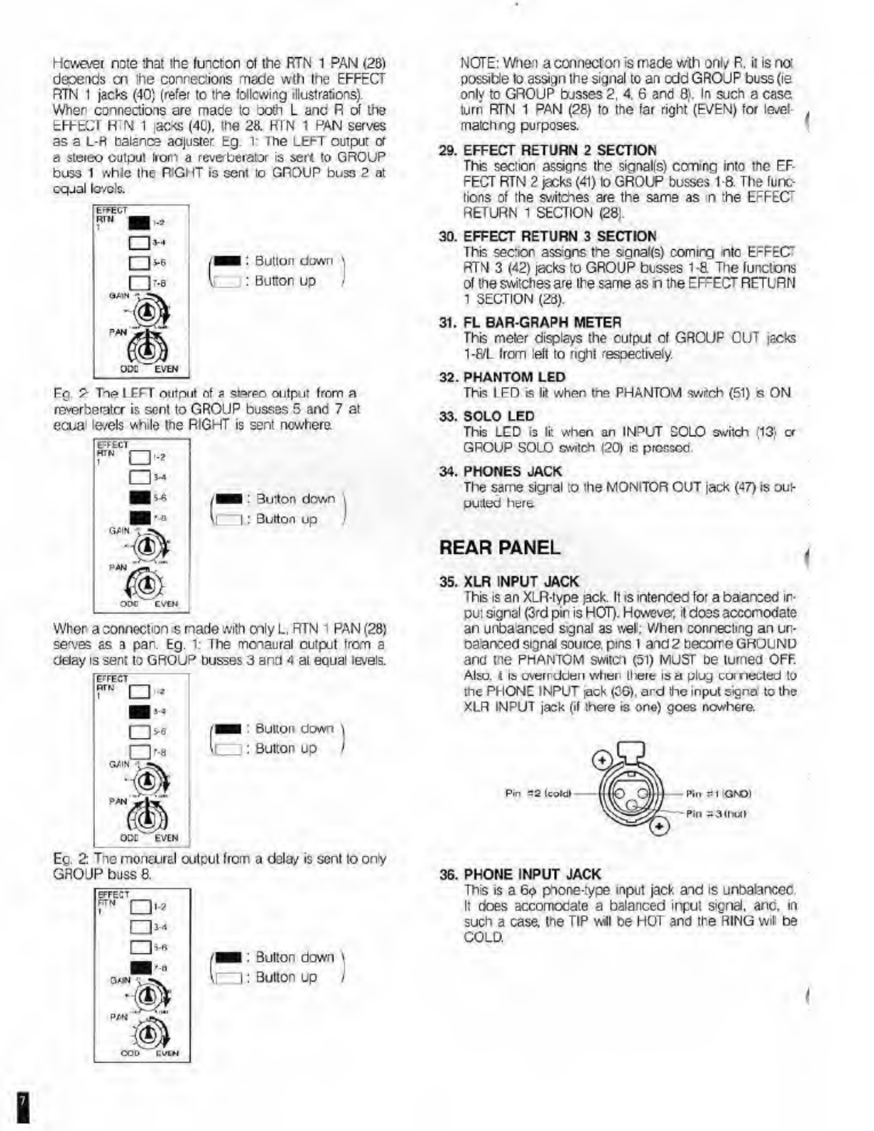
Hcwevei
nute
that
the
function
ol
the
RTN
1
PAN
(28)
deoends
cn
the
connections
made
wth
the
EFFECT
RTN
1
jacts
(40)
(refer
to
the
following
illustrations).
When
connections
are
mace
to
both
L
anc
R
of
the
EFFECT
H
N
1
:ac<S
(40),
the
28.
KIN
1
PAN
serves
as
a
L-H
Balance
adjuster
Eg
l:
The
LEFT
output
or
a
stereo
output
from
a
reverberator
is
sent
to
GROUP
buss
1
whle
the
RIGHT
is
sent
to
GROUP
buss
2
at
equal
levels.
Button
down
Button
up
Fg
2
Tne
I
FFT
output
of
a
stereo
output
from
a
reverberator
is
sent
to
GROUP
busses
5
and
7
at
ecua
le/els
while
the
RIGHT
is
sent
nowhere
Button
down
Button
up
When
a
connection
s
made
with
only
L,
RTN
i
PAN
(28)
sewes
as
a
par.
Eg.
l:
rhe
monaural
output
tram
a
delay
is
sent
to
GROUP
busses
3
and
4
at
equal
levels.
Ec.
2:
Tne
monairal
output
from
a
delay
is
sent
to
only
GROUP
buss
8.
NOTE:
When
a
connect
on
is
made
wth
only
R.
it
is
no:
possible
lo
assign
the
signal
to
an
edd
GROJP
buss(ie
only
to
GROUP
busses
2,
4.
6
and
8).
In
such
a
case
turn
RTN
1
PAN
(28)
to
the
far
right
(EVEN)
for
level-
match
ng
purposes.
29.
EFFECT
RETURN
2
SECTION
This
section
assigns
the
siqnalfs)
coming
into
the
EF¬
FECT
RTN
2
jacks
(41)
lo
GROUP
busses
t
8.
The
func¬
tions
of
the
switches
are
the
same
as
n
:he
EFFEC
RETURN
1
SECTION
(28).
30.
EFFECT
RETURN
3
SECTION
This
sec:ion
assigns
the
sgnal(s)
comirg
into
EFFEC"
RTN
3
(42)
jacks
to
GROUP
busses
1-8
The
lunctons
of
the
switches
are
the
same
as
h
the
EFFECT
RETURN
1
SECTION
(28).
31.
FL
BAR-GRAPH
METER
This
meter
displays
the
output
of
GROUP
CUT
jacks
1-8IL
Irom
left
to
nght
resoectively.
32.
PHANTOM
LED
This
LED
is
lif
when
the
PHANTOM
switch
(51)
s
ON
33.
SOLO
LED
This
LCD
is
li:
when
an
INPUT
SOLO
switch
(13)
cr
GROUP
SOLO
switch
(20)
is
prcssoc
34.
PHONES
JACK
The
same
sigral
to
the
MONITOR
OUT
jack
(47)
is
oui-
purted
here.
REAR
PANEL
35.
XLR
INPUT
JACK
This
is
an
XLR-type
jack.
It
is
mtenced
for
a
baarced
in¬
put
signal
(3rd
pin
is
HOT).
However,
it
does
accomodate
an
unbaanced
signal
as
well;
When
connecting
an
un-
ba
arced
signal
source,
pins
t
and
2
become
GROUND
and
tne
pfiantom
switch
(51)
MUST
be
turned
OFF.
Alto,
t
it
uverrdden
when
there
is
a
plug
cornecled
to
the
PHONE
INPUT
jack
(3G).
ard
the
input
signal
to
the
XLR
INPUT
jack
(if
there
is
one)
goes
nowhere.
Pin
36.
P
HONE
INPUT
JACK
This
is
a
6<?
pyione-rype
input
jack
and
is
unbalancec.
It
does
accomocate
a
balanced
input
signal,
and.
in
such
a
case,
the
TIP
will
be
HOT
and
the
RING
will
be
COLD.
B

37.
INSERT
JACK
F'om
This
jack.
the
post-FADER
signal
is
sent
oui.
possi-
b
y
to
an
effect
processor,
and
then
relumed
lo
Ihe
same
jeck
(see
illustration).
This
jack
is
used
mainly
when
hooking
up
effectors
which
modify
the
sound
source
sig¬
nal
iiseii,
such
as
compressors
limners
and
noise
gates
Tite
jack
is
of
a
stereo
phone-type
flP
is
SEND,
PING
is
RECEIVE).
II
nothing
is
connected
to
ll
>is
jack,
the
oignal
goes
straght
through
from
SEND
to
RECEIVE
doweeted
ic
IIk|
INSERT
I
Lring
rip
-*
li>
oliecior
(36ND)
from
elleclor
(RECEIVE)
N_
GND
Conncelod
Jo
nifJC
I
38
TAPE
INPUT
JACK
This
jack
is
usee
mairly
for
the
unbaanced
output
:
rom
the
mu
Wrack
recorder
in
use.
39
DIRECT
OUT
JACK
The
pcsf-FADER
signal
from
Ihe
particular
chanrel
is
outputted
frem
he*e
(unbalanced).
This
tack
may
be
used
lo
send
the
signal
to
effectors
40
EFFECT
RETURN
1
JACK
Normally.
he
output
from
Ihe
effectors
(unbalanced)
will
be
returned
here.
Tie
R
cf
this
jack
alsoacs
as
a
switch.
When
only
L
is
plugged
in
it
is
the
equivalent
ol
con*
rectng
the
same
sgnal
with
both
L
and
R
(ie.
the
L
sig¬
nal
will
be
spiced
equally
between
Land
R).
When
both
L
ard
R
are
plugged
in,
a
rormai
stereo
input
is
carried
through.
When
only
P
is
pluggec
in,
only
R
will
receive
the
signal.
41
EFFECT
RETURN
2
JACK
This
lunctidns
the
same
as
the
EFFECT
RTN
t
jack
(40).
42.
EFFECT
RETURN
3
JACK
Tms
functions
the
same
as
the
EFFECT
RTN
t
jack
(40).
43.
GROUP
BUSS
INPUT
JACKS
These
arc
the
input
jocks
tc
GROUP
busses
1-8/R.
Usually,
thaso
are
used
as
subsiderv
inputs
when
there
is
a
shortage
of
EFFECT
RETURNS
or
when
one
hooks
up
another
mixer
to
acheive
a
cascade
effect
44.
AUX
BUSS
INPUT
JACKS
These
are
the
input
jacks
lor
the
AUX
buss
(unbalanced).
Usually,
those
oro
used
when
cno
hooks
up
another
mixer
to
achieve
a
cascade
eltect.
45.
EFFECT
SEND
BUSS
INPUT
JACKS
These
jacks
arc
input
jacks
for
both
EFFECT
SEND
1
aod
SEND
2
busses
(unbalanced;.
Usually,
the
EFITCT
SEND
outputs
of
other
mixers
ere
connoctcd
hero
to
achieve
a
cascade
effect.
46.
GROUP
OUT
JACKS
These
(unbalanced)
oulp.il
jacks
for
busses
1-8
are
usually
conred.ec
wth
Ihe
inputs
to
multitrack
recorders
47.
MONITOR
OUT
JACKS
The
signal
eelcctcd
by
oithcr
MONITOR
SELECTOR
(25)
or
the
SOLO
buss
signal
(when
n
use)
is
sent
here
(un¬
balanced)
a'ter
its
le\el
oehg
adjusted
by
Ihe
MONITOR
LEVEL
knob
(26)
II
may
be
used
:o
hook
up
speakers
lor
monitoring
pu'pcses.
48.
AUX
OUT
JACKS
These
a*e
the
output
jacks
for
the
AUX
buss
(un¬
balanced)
They
are
usually
connected
to
he
inputs
of
an
effector.
49.
EFFECT
SEND
2
JACK
This
ie
the
outpU
jeek
f<x
the
EFFECT
SEND
2
bu3s
(unoalancec).
t
is
usually
contacted
with
the
input
ol
an
effector
50.
EFFECT
SEND
1
JACK
This
is
the
output
jack
lo-
th©
EFFECT
SEND
1
buss
(unbalanced),
t
is
usually
connected
with
the
input
ol
an
effector.
51.
PHANTOM
POWER
SWITCH
When
this
switch
is
ON,
a
DC24V
current
will
be
suppled
to
pins
2
and
3
cf
tho
INPUT
jacks
(35)
and
(36)
for
oil
channels
When
connecting
a
condonsor
microphono
turn
Ihe
PHANTOM
switch
ON.
NFVFR
conned
a
dy¬
namic
merephone
when
the
switch
is
ON:
It
MUST
be
turned
OFF
when
the
microphone
has
no
need
for
an
exterior
power
supply.
52.
PEAK
HOLD
SWITCH
When
this
switch
is
ON
the
peak
level
indicated
oy
the
FL
meter
(31)
will
be
held
for
approximately
4
seconds.
When
it
B
OFF,
Ihe
oeak
level
will
net
be
held
53.
POWER
SV/ITCH
After
turning
on
the
power
to
this
unit,
the
muting
time
will
be
about
5
secords
54.
MIDI
EXPANSION
SLOTS
This
space
is
alottod
lor
future
use
with
MIDI
control.
Do
not
remo/e
Ihe
panel,
since
this
may
result
in
damage
lo
this
unit
Mountng
wil
be
dor©
at
the
Service
Staton
level.
55.
POWER
CORD
I
<.
Bi
llkl
5190k
sSSz.
ereaas
viiiicn
aua
C’-oaii
clc
|
-
1
10
ino
ongmr.
SECTION
5
CONNECTING
EFFECTORS
Numerous
kinds
ol
sound
manipulations
are
earned
out
during
a
multitrack
recording
through
the
use
ot
various
sound
orccesso's.
Depending
on
the
usage
of
a
particular
p-occcEor.
conncctons
to
the
Vlcdc
8t2
may
vary.
Plcaec
reler
to
the
foflowing
illustrations.
1
When
processing
an
effect
on
a
particular
channel
(eg
compressors,
limiters,
delays,
etc)
section
4
THE
PARAMETRIC
EQUALIZER
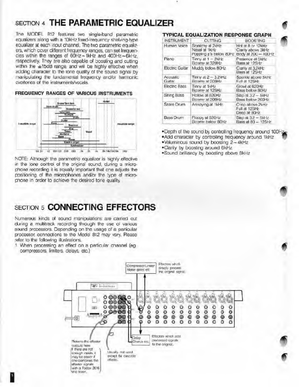
NOTE:
Although
the
parametre
equalizer
is
highly
effective
in
the
tore
control
ol
the
original
sound,
during
a
micro
pnone
recording
it
is
equally
important
that
one
adjusts
the
posrioninrj
of
the
microphones
and/or
the
type
of
micro¬
phone
in
order
to
achieve
the
desired
tore
quality
The
MODFl
fll?
features
two
single-band
parametric
equalizers
along
with
a
10
kHz
fixed-trequeno/
shebirrj-fype
eauali
2
er
at
each
input
channd.
The
two
parametric
equaliz¬
ers,
which
covet
efferent
frequency
tanges.
ran
set
frequen¬
cies
wthin
the
ranges
of
60Hz~1kHz
and
40DH?-6kHz,
respectively.
Ihey
are
also
capable
of
ooostng
and
cutting
within
the
±ibdB
range
and
wil
ce
highly
effective
when
addng
character
to
the
lone
qudity
of
tne
sound
signal
Dy
manipulating
the
fundamental
frequeicy
and/or
hatmonic
cvcrtorcs
of
the
instruments/vocals
FREQUENCY
RANGES
OF
VARIOUS
INSTRUMENTS
TYPICAL
EQUALIZATION
RESPONSE
GRAPH
INSTRUMENT
Cl
TTNG
BOOSTINC
fHiimanVbira
1
Scratchy
at
2
kHz
Nasal
at
ikH;
Hoppiry
P'S
Dfck>v
t!UHz
Hot
at
8
or
12kHz
Gant/
above
3kHz
BCOy
at
20C
-
JUU-iZ
Piano
Timy
at
1
-
2hlte
Roomy
at
320Hz
Presence
at
5kHz
Bass
at
125Hz
Etectrc
Guitar
Muddy
below
8CHz
Gant/
at
32kH’
Bass
at
125Hz
Acoustic
Tin
ly
at
2
-
3.2kHz
Guitar
Roomy
at
POOH?
Spill
Klli
aL'UrtJ
OKHZ
Full
at
125H7
Efectrc
Bass
rimy
at
1kHz
Boomy
at
125Hz
G’CANl
at
62CHz
Bass
below
80Hz
string
Bass
Holow
at
62CH/
Boomy
at
200Hz
Sepal
3,2
-
5kHz
Bass
botow
20CHz
Snare
Drjm
Amoyngat
1kHz
Crisp
above
PkHz
Full
at
125Hz
beep
at
30Hz
Boss
Drum
Floppy
at
62CHz
Boomy
below
8CH?
Sepal
3.2-
5kt
lz
Bass
at
80-
125Hr
•Cepth
of
the
sound
by
controlling
‘requeue/
around
ICQH/^
•Add
character
by
cortrolmg
frequency
around
1kHz
“
•Volutrurous
sound
by
bcosing
2-4kHz
•Clarity
by
bcosing
around
6kHz
•Sound
orilliancy
by
hooding
above
8kHz

2.
When
processing
a
common
elect
on
all
channels
but
with
amcuni/perspective
adjustments
made
per
channel
(eg
reverberators,
exciters,
cfc)
5-gnas
sc.1
1C
me
EFH-C
StNO
1
(5)
svu
hw
a
mill.
rttricr
procefs
Hi'
post-FADE?
Sijna
&gna$
sem
so
me
EFFECT
S6ND
2(7)
wfl
have
a
Re.«ler
<w
(ikxcw
iho
signal
itfooeo
*«n
Hie
>Ei\D
2
SELECTOfi
(
6
)
Signas
wrl
In
llio
&UX
GAIN
(9)
will
h**-
p
BswbefUo-
the
ixgtieb
wilxtuj
»h
Hhj
AJX
S£L£CIOfl
O)
By
us*t)|.
i
xi
AM
PAN
(IQ.
me
pyserecw?
a
Uieaortfs
may
bo
sa
as
v«l,
u
dbooooooooo
opooooooooo
oooooooooo
Used
»men
ihc
disccr
is
d
a
rftrco-«i|X(
type
feeclw*
w«l
coaif
'I
she
ellectc*
ouipiil
:
coinoxeo
ikjo
section
6
CONNECTING
PERIPHERAL
EQUIPMENT
1.
IMPEDANCE
Input
and
output
mpedarces
should
be
consdered
when
cornectirg
this
unit
to
other
equipment.
Impedance
is
the
resistance
vaue
against
alternating
cur¬
rents.
such
as
sound
signals
and
the
unit
used
is
the
U
pi
m).
II
the
output
ki
peda
ioo
d
a
gven
unit
dees
not
mach
the
hput
impedance
of
arother,
this
nay
result
in
round
distortion
or
even
a
oreakdown.
In
general,
:he
rule
of
tnumb
is
that
the
output
impedance
should
be
low
(low
out)
anc
the
input
impedance
should
be
high
(high
in).
Refer
to
SPECIFICATIONS
for
the
input
and
output
im¬
pedances
oi
ths
unit.
Mote:
Always
use
a
Direct
Box
when
connecting
outputs
indicated
in
watts
(W),
sLch
as
those
of
an
amplfiet
cr
when
connect
ng
instruments
which
require
high
input
impedances
Failure
:o
do
so
may
result
in
damage
to
the
power
amplifier
circut
as
well
as
the
unit
itself
2.
ADJUSTING
INPUT/OUTPUT
LEVELS
'he
level
aefusment
ol
the
incormrg
signal
to
INPUT
jocko
(35)
or
(36)
is
done
with
rhe
TR
W
(2)
so
as
tc
prevent
the
frecuent
Hashing
of
the
PEAK
LED
(1).
ADJUSTMENT
PROCEDURES
First,
set
the
NPIT
FADER
(15)
within
the
C±odB
range
since
ths
range
is
where
the
least
loise/distorton
occu's.
Then
adjust
he
input
signal
using
the
TRIfi/
dial
(2).
The
TRIM
is
-60dBV
(microphone
level)
when
turned
to
the
iar
right
and
-
ICdBV
(lire
level)
when
furnec
to
the
Iar
eft.
While
adjusting
the
signal,
it
may
be
corvenienl
to
press
the
INPUT
SOLO
switch
(13)
of
the
particular
channel.
enabling
monitoring
of
the
post-FADER
signal.
In
addition,
please
ncte
that
the
PEAK
LED
will
also
Igh;
when
the
signal
to
the
EQUALIZER
SECIION
(4)
is
oveloaded.
Wnen
adjusting
with
the
TRIM,
it
S
highly
recommended
that
al
EQUALIZER
gains
be
turned
to
the
licit
portion.
1
,
after
the
trirnmng
is
finshed
and
the
desired
tone
quality-
adjusted,
the
PEAK
LED
still
turns
on,
them
s
overloading
at
the
EQUALIZER
stage
and
either
the
input
signal
itself
should
be
adjusted
or
the
trimming
be
done
ovar
again
All
ths
nominal
inpul/output
impedances
for
this
unit
except
for
inputs
to
INPUT
jacks
(35)
and
(36),
ore
10dBV
(D.3V).
there-ore
allowing
drect
hookups
to
most
recording
equip¬
ment
Hnwever.
for
connections
with
equlpmer*
with
differing
ncminal
impedances
or
professicna
equpment
(+4dRm
etc.),
an
attenuator
or
ine
amplifie'
(FOSTEX
5030
etc)
will
be
necessary.
B
section
7
BASIC
SIGNAL
FLOW
Ir
general
ihe
base
(low
oJ
tLie
sound
signal
Gunrg
a
rruiTt-
trdck
reuerdng
can
be
sepaialed
info
(lie
following
two
routc3:
Rout©
1:
Recording
the
inputted
sound
sources)
to
a
multi
track
reccrder
Route
2:
Montorng
the
output
?ional(s)
of
a
multitiaclc
reco'der
while
recording
To
illustrate
these
two
routes.
we
will
assume
a
live
recording
using
a
Model
812
mixer
and
a
Fcstex
R8
muititrack
recorder
(Refer
to
the
following
illustration).
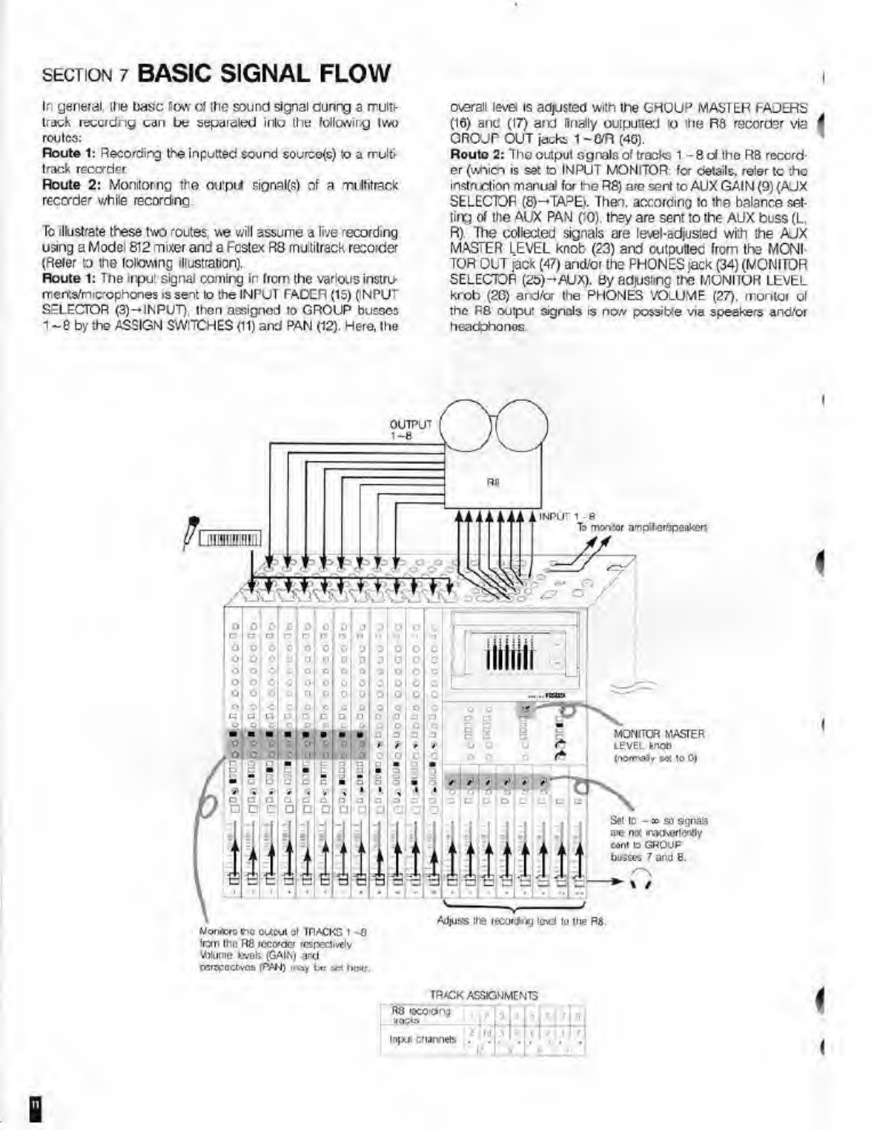
Route
1:
The
input
signal
coming
in
from
the
various
instru
merr.s/mic'ophones
is
sent
to
the
INPUT
TADER
(15)
(INPUT
SELECTOR
(3)-INPUT),
then
assigned
to
GROUP
busses
1
-
8
by
the
ASSIGN
SWITCHES
(11)
and
PAN
(12).
Here,
the
overall
level
is
adjusted
with
the
GROUP
MASTER
FAJERS
(16)
and
(17)
and
finally
outputted
to
ihe
R8
recorder
via
OROJP
OUT
jacks
1
-Q/R
(4G).
Route
2:
The
output
sgnals
of
tracks
1
-8
of
the
R8
reccrd
er
(which
is
set
to
INPUT
MONITOR
for
details,
reier
to
the
instruction
manual
for
the
R8)
are
sent
to
AUX
GAIN
(9)
(AJX
SELECTOR
(8)—TAPE).
Then,
according
to
the
balance
set¬
ting
of
the
AUX
PAN
CO),
they
are
sent
to
the
AUX
buss
(L.
R)
The
collected
signals
are
level-adjusted
with
the
AJX
MASTER
LEVEL
knot
(23)
and
outputtec
from
the
MONI¬
TOR
OUT
jack
(47)
and/or
the
PHONES
jack
(34)
(MONITOR
SELECTOR
(25)-AUX).
By
adjusting
the
MONITOR
LEVEL
krob
(2G)
and/or
the
PHONES
VOLUME
(27).
monlor
o(
the
F8
output
signals
is
now
possible
via
speakers
and/or
headphones.
OUTPUT
INPUT
1
To
monitor
amp'lcr/speakers
MONfTCR
MASTER
LEVEL
MOD
(no«''aly
e«
io
0
)
Set
ic
-
»
so
agnail
are
no:
inadvertently
coni
to
GROUP
bosses
7
and
8.
Adiuss
lie
reoortfng
lev)
lo
Ihe
R8
Von<c»G
tfto
ot/cul
at
TRACKS
1
-8
Iron)
Iho
R8
recorder
respectively
\Wume
fcvofe
(GAIN)
and
parrcoaivos
(PAN)
may
be
ae<
lictc
ImMlil
T8/CK
ASSIGNMENTS
ny
loco
dh^
,
J
b
|
<
i
7
II
in)*!
channels
.
1
17
t
I
?
■
•
•
B
SECTION
8
MULTITRACK
RECORDING
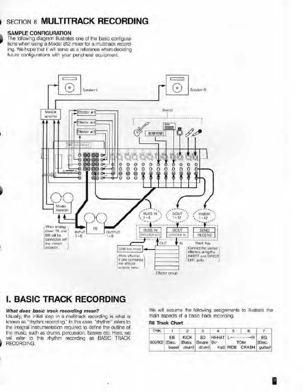
SAMPLE
CONFIGURATION
The
blowing
diagram
illustrates
one
of
the
basis
configura¬
tions
wher
using
a
Model
812
mi«er
lor
a
multirack
record¬
ing.
YVe
hope
that
ii
wil
ssrve
as
a
reference
wfien
deciding
future
configurators
with
your
peripteral
equipment.
I.
BASIC
TRACK
RECORDING
What
docs
basic
track
recording
mean?
Usualy,
the
initial
step
m
a
multirack
recorctng
is
what
is
known
as
"'hyhn
recording'
In
this
cas=
’rhythm"
refers
to
the
in:egral
instrumentation
required
io
defne
the
outline
of
the
muse,
such
as
drums
percussion,
basses
eta
Here,
we
wil
refe-
to
this
rhythm
recording
as
BASIC
TRACK
RECORDING.
We
w
II
assume
‘he
Mowing
assgrments
to
illustrate
th©
main
aspects
ot
a
basic
track
recording
R8
Track
Chart
1
TRK
1
.
2
3
4
1
5
]
6
r
EB
SOURCE
(Elec.
base)
KICK
(Bass
drum)
SD
HHHAT
L—
■
—
R
EG
(Snare
(hi-
TOM
(Elec,
drjml
hat)
RICE
CRASH
guitar)

Look
at
Figure
1.
This
configuration
is
intend©:!
so
that
the
sojnd
sgnals
of
the
drums
and
electric
bass
pic<ed
ud
by
a
mutii-mcrophone
are
recorded
tc
the
R8
recorcter
with
the
above
track
assignments
After
trimming
the
input
gains
and
adiusiing
the
‘one
quaity
,
(refer
tc
pg.
ADJUSTING
INPLT/OUTPUT
LB/ELS
and
pg.
THE
PARAMETRIC
EQUALIZER),
we
will
set
the
necessary
controls
fcr
this
basic
track
recording.
'
Figure
DRUMS
CRASH
INPUT
GROUP
OUT
I-8/R
Adjjsts
the
amoLnt
01
raverperaton
P<CCC33CC
on
:he
monitor
sgnals
fa
TRACKS
1
-5
respectively
EFFECT
SEND
2
Rcvert>
Adiisls
the
arriount/p^spectr/o
oi
tne
nvoniux
signals
d
TRACKS
t
-5
respectively.
Adjusls
the
total
level
of
tne
processed
signals
Adjusts
the
ontpiil
levels
to
TRACKS
1:
BASC
TRACK
RECOFONG
JL
'L
OUTPUT
1
1-8
RR
_r^
CYM
TO
612
TAPE
IN
1-8
o
o
o
o
o
□
.
Cl
c
c
I
ol
O
0
0
0
o
o
o
o
o
°
0
o
0
o
0
0
o
0
c
o
o
o
o
o
o
o
o
o
L-R:
Morvias
the
processed
signais
AUX.
Mentors
tho
cngnal
signals.
SENDING
THE
SIGNALS
TO
THEIR
DESIGNATED
TRACKS
Track
1:
Since
tho
output
from
the
GROUP
OUT
ack
1
(46)
gees
to
track
1
of
tne
R8,
vie
want
to
send
the
post-fader
cicna
of
chamol
0
to
CROUP
buss
1
(INPUT
SELECTOR
(3)->INFUT,
ASSIGN
SWITCH
(11)-»1-2,
PAN
(12J-OCO).
Next
we
want
to
adjust
the
level
of
the
signal
to
GROUP
OUT
jack
1
(46).
sine©
this
will
h©
the
recording
level
d
the
traek.
We
co
this
by
adjusting
GROUP
MASTER
FADER
1
(16)
while
monitoring
the
level
with
the
FL
METER
for
Irack
1
(31).
Note:
In
this
c-xampia
we
wi
use
GHOUP
busses
7
aid
8
lor
moni'oring
the
reverberation
effect
and
therefore,
o
avod
unJesired
signals
entering
these
busses,
tun
all
of
lie
GROUP
TO
L-R
GAINS
(18)
to
{far
left).
Track
2:
Here
we
want
tc
send
the
KICK
signal
of
channel
1
to
GROUP
buss
2.
The
process
is
similar
to
that
of
TRACK
1:
Adusling
the
total
send
level
with
the
GROUP
MASTER
FADER
116)
while
monitoring
the
FL
LEVEL
METER
(31)
for
GROUP
buss
2
etc.
Tracks
3
&
4:
VVe
warn
to
record
Ihe
TOMS.
HH.
CRASH
and
RIDE
to
TRACKS
3
&
4
wth
a
stereo
oerspectve
Firs:,
lor
all
Ihe
channels
Irom
2
through
7.
we
select
3-4
using
the
ASSIGN
SWITCHES
of
these
channels.
Then,
by
lurning
the
PAN
(12)
as
shown
ri
Figure
1
we
determine
the
p
o-
portion
of
the
signal
to
be
split
between
GROUP
busses
3
aid
4.
For
oxamplo,
tho
LOW
TOM
(chonnol
2)
will
bo
cont
only
to
GROUP
buss
3
(PAN
(8)-»Om).
while
the
HH
(channel
5)
will
be
sent
to
both
busses
with
a
bias
towards
GROUP
buss
4
(PAN
(8)-*somewhat
more
towards
EVEN.)
The
final
step
wil
be
to
adjust
the
total
output
le/el
with
the
GROUP
MASTER
FADERS
(16)
for
busses
3
and
4.
When
monitorng
the
output
le/el
with
the
FL
METERS
(31),
set
the
FADERS
to
0.
Then,
after
adjusting
the
reative
levels
with
the
INPUT
FADERS
(15),
if
the
METERS
(31)
indicate
an
ever
levet,
instead
of
adjusting
with
GROUP
MASTER
'
FADERS
(16).
lower
all
INPUT
FADERS
(15)
for
channels
2-7
until
the
necessary
level(s)
is
achieved
Again,
a
reminder
that
all
GAINs
in
Ihe
GROUP
TO
L-R
i
SEC'ION
(18)
should
be
set
to
-<»
smee
GROUP
bosses
7
and
3
will
oe
used
for
monitoring
in
this
example.
■
Rack
5:
Here,
the
SD
signal
of
channel
8
is
sent
to
TRACK
5
via
GROUP
buss
5
in
:he
same
manner
as
TRACK
1.
Effect
Processing
Usually,
effect
processing
is
done
during
a
mix-down
and-or
a
ping-pong
recording
and
not
at
this
stage,
however,
we
wil
illustrate
one
example
where
a
oompressor/limiier
is
processed
onto
the
ELECTRIC
BASS
(EB)
signal
and
a
re/eroeration
onto
the
TCMS
(*3).
COMPRESSOn/LIMlTCR
-CD
Connect
a
compressor/limiter
to
the
INSEFT
jack
(37)
cf
charnel
9
(refer
to
INSERT
)gck
tor
procecures).
An
tB
signal,
Deing
modilied
by
tne
compressor/limiter,
will
now
be
recorded
to
TRACK
1.
REVERBERATOR-TOMS
(x
Several
methods
are
possible
but
here
we
will
use
the
EFFECT
SEND
1
(5).
Conrect
the
EFFECT
SEND
1
jack
(50)
with
the
input
cf
the
reverberator
and
the
output
o'
the
reverberator
with
the
EFFECT
RTN
1
jack
(40)
1.
Set
the
SEND
1
MASTER
LEVEL
knob
(21)
to
0
and
adjust
the
amounts
of
the
signals
to
be
sere
tc
the
reverberator
by
using
the
respective
EFFECT
SEND
1
of
channels
2-4.
2.
Send
the
outout
of
tie
reverberator
to
GROUP
busses
3
aid
4
(RTN
1
ASSIGN
SWITCHES
(28)-3*4.
RTN
1
PAN
(28)—center.
RTN
1
GAIN
(28)-0)
Now
the
reverberated
signals,
as
wel
as
the
original
sig¬
ner;
of
the
TOMS
will
be
recorded
to
TRACKS
3
and
4.
MONITORING
Through
the
use
of
the
EFFECT
SEND
2
(7),
Ihe
Model
612
is
capable
of
processing
an
ehec
on
the
monitor
signal
of
an
irooming
output
from
a
recorder.
This
feature
alows
for
a
more
flexible
monitoring
environment
wnere
one
can
dmulato
the
desired
total
offect
without
affect¬
ing
v/ith
the
signals
being
seni
to
the
recorder.
In
the
example,
we
will
use
a
reverberator
to
process
the
II.
OVER-DUBBING
What
does
'over-dubbing
”
mean?
O/er-dubbing
is
the
process
ol
recording
a
new
sound
source
to
a
new
sound
track
while
simultaneously
playing
back
the
rest
oi
the
tracks
wth
the
recording
head
(syn¬
chronous
play-back).
Look
at
Tigurc
2.
This
configuiation
is
intended
so
that
the
sound
signal
from
Ihe
ELECtRlC
GUITAR
(EG)
wifi
be
"ovor
dubbec"
to
TRACK
6.
TRACKS
1
-5
will
be
monitored
dur¬
ing
their
synchronous
play-tack
Also,
a
delay
effect
will
be
processed
on
the
EG
signal
and
also
sent
to
TRACK
6
The
procedures
fer
sending
ihe
EG
signal
to
TRACK
6.
montoring
the
recorder
outputs
for
TRACKS
1
-6
and
piccessng
a
reverberation
on
the
monitor
signal
are
all
the
same
as
in
the
BASIC
TRACK
RECORDING
section.
monitor
signal.
The
monitoring
netnods
for
the
outputs
to
TRACKS
I
-5
sv.ll
be
the
same
es
BASIC
SIGNAL
Flow
or
pago
11.
Sending
the
Signal
to
the
Reverberator
Firsl
select
AUX
with
the
SEND
2
SELECTOR
(6)
for
channels
1-5.
This
has
the
purpose
o'
sencing
the
incoming
TAPE
sgrals
(AUX
SELECTOR
(8|—TAPE)
to
the
EFFECT
SEND
2
buss
Alter
adjusting
the
respective
AUX
Gain
(9)
and
EF¬
FECT
SEND
2
LEVEL
knobs
(7),
tbs
signals
wll
be
sent
lo
the
SEND
2
busa
and.
alter
a
f
nd
adjustment
with
tho
SEND
2
MASTER
LEVEL
knob
(22).
routed
to
tne
reverberator.
Monitoring
the
Processed
Signal
We
wil
equally
route
the
reverberator
output
from
ihe
EF¬
FECT
RTN
2
jack
(41)
tc
GROUP
busses
7
and
8
by
using
the
EFFECT
RTN
2
SECTION
(29)
(RTN
ASSIGN
SWITCHES
(29)-*7-8.
RTN
PAN
(29)-cente-.
FTN
GAIN
(29>-0).
The
lev^is
ol
the
signals
can
new
be
adjusted
with
the
MASTER
TADERS
for
71
1
and
0/R
(17)
Then,
by
3electng
L
R
with
the
MONITOR
SELECTOR
(25).
it
is
now
possible
to
monito-
the
processed
TRACKS
1
-5
with
Ihe
use
of
neadphones
or
speakers
connected
with
the
MONITOR
OUT
jack
(47i
andfor
PHONES
jack
(34).
(Selecting
AUX
will
enable
moni¬
tor
of
the
original
signal.)
Note:
For
this
example,
do
net
select
GROUP
busses
olhe*
nan
7-
6
with
the
RTN
2
ASSIGN
SWITCHES
since
this
wil
create
an
infinite
loop
This
will
result
in
the
processed
signet
to
be
ecorded
to
TRACKS
1
-5
and
could
cause
howling
(feedback).
For
example,
if
the
channel
5
signal
is
Peng
sent
to
the
EFFECT
SEND
2
buss
and
5-6
is
selected
at
the
RTN
2
ASSIGN
SWITCHES
(29).
the
following
Icop
wil
be
created.
ch.5
EFFECT
SEND
2-Reverberator-GROUP
buss
5-
TRACK
5-Ch,5
AUX
GAIN
In
erder
to
prevent
creating
loeps
as
above,
it
is
also
possible
to
connect
the
reverberator
output
to
the
AUX
BUSS
IN
jack
(44)
and
monitoring
it
by
select
ng
AUX
of
the
MONITOR
SELECTOR
(25).
However,
m
this
case,
it
will
no!
be
possible
to
adjust
Ihe
master
level
of
the
processed
signal.
For
processing
the
delay
effect,
the
EG
signal
will
oe
sent
to
tie
processor
via
the
DIRECT
OUT
jack
(39)
and
'he
output
Iron
the
processor
will
be
sent
to
the
INPUT
jack
(36)
cf
channel
12
and
routed
to
GROUP
txiss
6
along
with
the
original
sound
signal
(ch.12
INPUT
SELECTOR
(3)-
NPUT,
ASSIGN
SWITCHES
(11)-5
€,
PAN
(I2)-EVEN).
In
doing
so.
the
volume
ba'oncoc
ol
tho
EG
signal
ard
is
prococsod
signal
can
oo
adjusted
individually
by
usinc
the
INPUT
FADFRS
(15)
o'"
channels
10
and
12
respectively.
Individual
equalizing
is
also
possible
Note:
The
EFFECT
SEND
2
knobs
(7j
ler
channels
10
and
12
should
be
set
to
-
a.
in
order
to
avod
the
signals
entering
Ihe
EFFECT
SEND
2
buss
and
distorting
the
reverberation
balances
while
monitoring
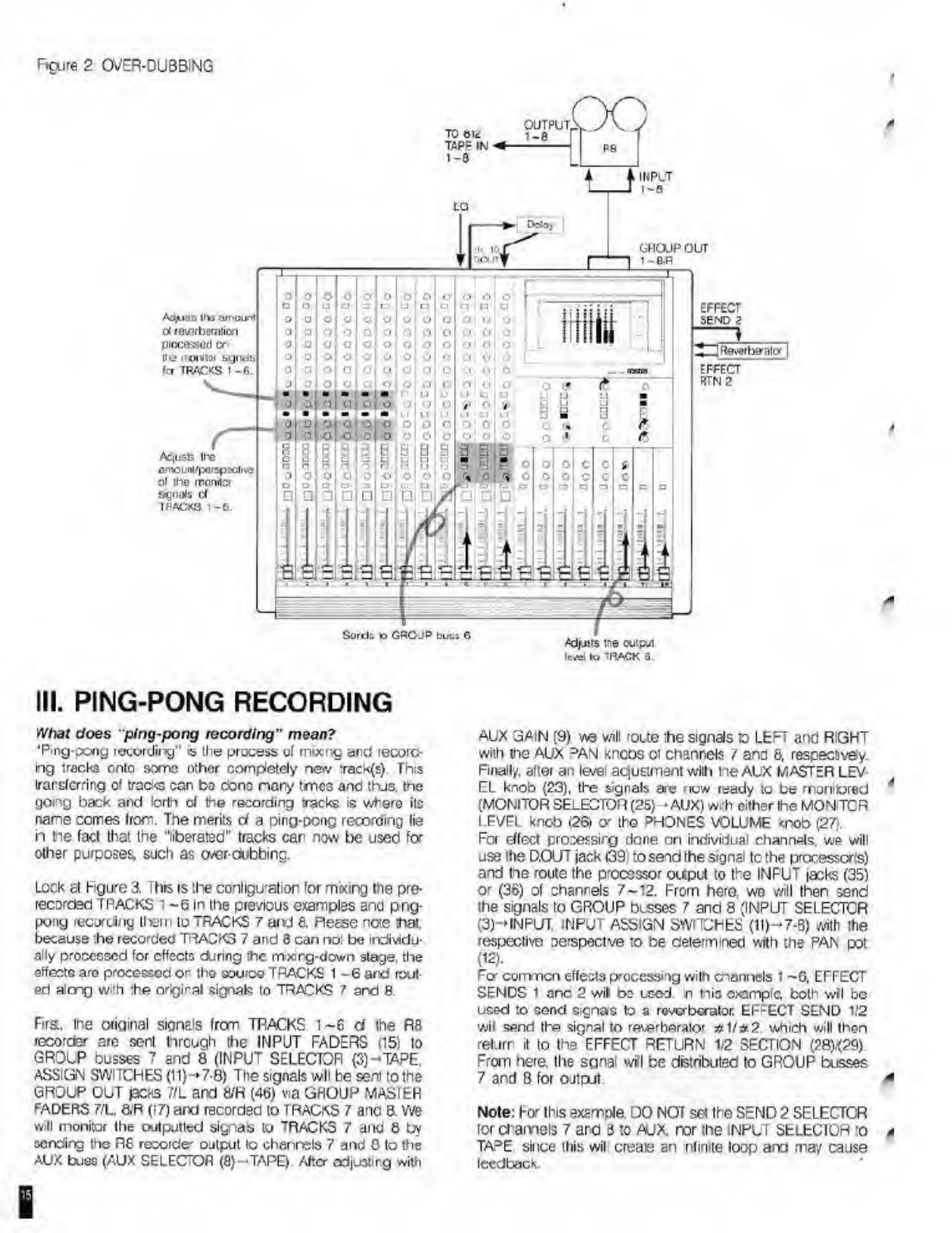
Figure
2
OVER-DUBBING
*
OUTPUT,
i-a
INPUT
GROJP
OUT
i
-an
Ad^iaa
n»
amount
ol
reverberation
C
jReverbgator
|
lie
ir©ni»r
sgnete
fcr
TRACES
1
-
6
.
Aqusfc
ll'c
omou
«/
(Xi
r
sp
!>clive
ol
ihe
monrtci
&gnals
d
TPfl£K3
1
-6.
Sorda
O
GROJP
bus;
6
Ajjjsts
ine
outpui
lev*!
lo
'RACK
0.
0
0
o
o
o
o
1
o
1
o
o
O
Ol
o
o
o
u
Ci
a
□
In
ci
□
n
n
p
3
□
o
O
o
o
o
o
o
O
O
O
0
0
'
o
O
o
o
o
o
•
o
o
o
3
u
o
o
o
0
0
0
o
o
o
o
O
:,
o
!
o
1
G
o
o
o
o
O
o
O
0
o
1
o
1
o
o
o
o
o
o
o
o
3
Lai
o
1
o
j
Q
I
o
|
o
|
o
°
o
o
o
•
.'I
s's
:
o
j
o
j
o
o
(.
,
-
III.
PING-PONG
RECORDING
What
does
"ping-pong
recording"
mean?
‘Ping-pong
recording”
is
the
process
of
mixnc
and
recorc-
ing
tracks
onto
somo
other
completely
new
:rack(s).
This
transferring
of
traci<s
can
be
Cbno
nary
tmc3
and
thj3.
Ihe
gong
back
and
forth
of
the
recording
tracks
is
where
its
name
comes
from.
The
merits
d
a
ping-pong
recording
lie
h
tie
fact
that
the
"liberated"
tracks
car
now
be
used
to¬
other
purposes,
such
as
<*erdubbinc.
Lock
at
Figure
3.
i
his
is
the
conligu'ation
tor
mixing
the
pre¬
recorded
TRACKS
1
~6
in
the
previous
examples
and
png-
pong
recording
tlxeiri
to
TRACKS
7
and
8.
Reese
note
that,
because
:he
recorded
TRACKS
7
and
8
can
no:
be
individu¬
ally
processed
for
effects
during
the
mxirg-down
stage,
the
effects
are
processed
or
thG
source
TRACKS
1
-6
and
rout¬
ed
almg
with
the
nrigiral
signal?
to
TRACKS
7
and
8.
Firs.
Ihe
original
signals
from
TRACKS
1-6
d
the
R8
records
are
sent
through
the
INPUT
FADERS
(15)
to
GROUP
busses
7
and
8
(INPUT
SELECTOR
(3)-TAPE,
ASSIGN
SWITCHES
(!1)-7-8)
The
signals
wll
be
sent
to
the
GROUP
OUT
jacks
7/L
and
m
(46)
Via
GHOUP
MASIbH
FADERS
7/L,
8.R
(17)
and
recorded
to
TRACKS
7
ano
8.
we
will
monitor
the
outputted
signab
to
TRACKS
7
and
8
by
sending
the
R6
recorde'
output
to
chenrels
7
and
0
to
the
AUX
buss
(AUX
SELECTOR
(8)—TAPE).
After
odjustirg
with
I
AUX
GAIN
(9)
w$
will
route
ihe
signals
to
LEFT
and
RIGHT
with
me
AUX
D
AN
kneos
oi
channels
/
and
8,
respectivey.
Finally,
after
an
level
aejustment
with
the
AUX
MASTER
LEV¬
EL
knob
(23),
the
signals
are
now
ready
to
be
monitored
4
(MONITOR
SELECTOR
(25)-
AUX)
with
either
the
MON
ICR
LFVFI
knob
.26.
<y
th©
PHONES
VOLUME
<nob
(27).
For
effect
processing
done
on
individual
channels
we
will
use
the
D.OUT
jack
i39;
to
send
the
signal
to
the
processors)
and
he
route
the
processor
output
to
the
INPUT
jacks
(35)
or
(36)
of
channels
7-12.
From
here,
wo
will
then
send
the
signals
to
GROUP
busses
7
and
8
(INPUT
SELECTOR
(3)—INPUT
INPUT
ASSIGN
SWITCHES
(1l)-7-8)
with
the
respective
oerspectve
to
be
determined
with
the
PAN
pot
(
12
).
Fq-
common
effects
processmg
with
channels
1
-G,
EFFECT
SENDS
1
one
2
wit
bo
used.
n
this
example,
both
wil
be
used
to
send
signas
to
a
reverberator.
EFFECT
SEND
1/2
wil
send
the
signal
to
reverberator
#
1/2
2
which
will
then
return
it
to
the
EFFECT
RETURN
1/2
SECTION
(?8)<29)
From
here.
Ihe
sgnal
will
be
distributed
to
GROUP
busses
7
and
8
for
ojtput.
*
Note:
hor
this
example.
DO
NOT
set
the
SEND
2
SELECTOR
for
enamels
7
and
3
to
AUX.
nor
the
input
SELECTOR
:o
a
TA
D
E
since
this
wil
create
an
nfimte
loop
and
may
cause
feedback.
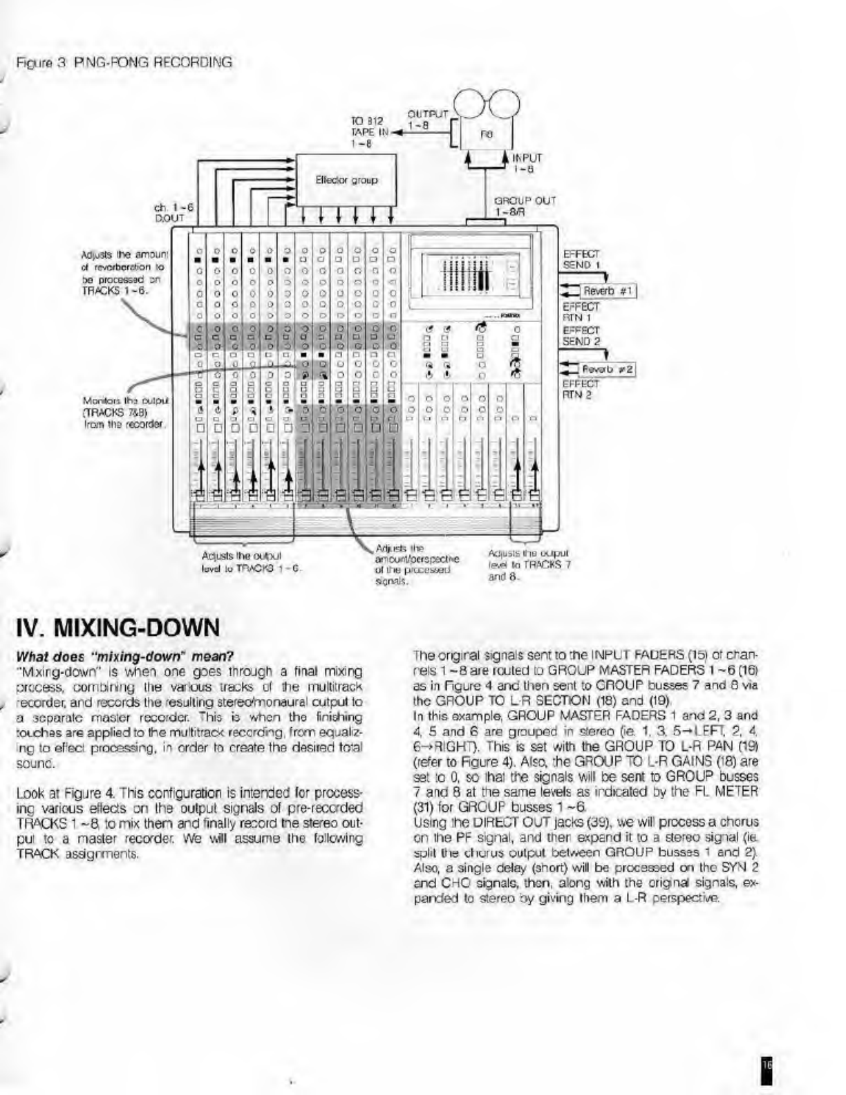
RQirft
3
PNG-FONG
RECORDING
IV.
MIXING-DOWN
What
does
“mixing-down*
mean?
'Mxirg-down"
is
when
one
goes
through
a
final
mixing
ixccess,
combining
the
various
tracks
ol
the
multitracK
-eccrder.
and
records
the
'esjlling
sterec/m.onaural
cutput
lo
a
separate
mosier
recorder,
"his
b
when
tho
finishing
:occh»s
are
applied
to
the
multitrad*
reccrchg.
from
eqaaliz-
ng
to
ePect
processing,
in
order
to
create
the
desired
feral
sounc.
Look
at
Figure
4.
This
configuration
is
intended
for
process¬
ing
various
effects
on
ths
output
signals
ol
pre-recorded
TRACKS
1
-8.
to
mix
then
and
finally
record
tne
stereo
out-
pul
to
a
naster
recorder.
We
wil
assume
tho
following
TRACK
assignments.
rhe
original
signals
sent
to
:ne
inpui
hAUERS
(ibi
or
cran-
r
els
1
-8are
railed
to
GROUP
MASTER
FADERS
I
-6
(16f
as
in
Tgure
4
and
then
sent
to
CROUP
busses
7
and
8
via
the
GROUP
TO
L-R
SECTION
(18)
and
(19)
In
this
example,
GROUP
MASTER
FADERS
1
and
2,
3
and
4,
S
and
6
are
grouped
in
stereo
(ie.
1.
3.
5-»LEFT.
2.
4.
6-+RIGHT).
This
is
set
with
the
GROUP
TO
L-R
PAN
(IS)
(refer
to
Figure
4).
Also.
the
GROUP
TO
L-R
GAINS
(18)
are
set
lo
0.
so
lhai
the
signals
will
be
sent
to
GROUP
busses
(
and
8
at
the
same
levels
as
indicated
by
the
FL
METER
(31)
for
GROUP
busses
1
~6
Using
ihe
DIRECT
OUT
jacks
(39),
\ve
wil
process
a
chorus
on
tine
PF
signal,
and
ther
expand
it
to
a
stereo
signal
(ie
spill
the
chorus
output
between
GROUP
busses
1
and
2}
Also,
a
single
delay
(short)
will
be
processed
cxi
the
SYN
2
ervd
CRC
signals,
then,
along
with
the
origins
signals,
ex¬
panded
to
stereo
oy
giving
them
a
L-R
perspective.
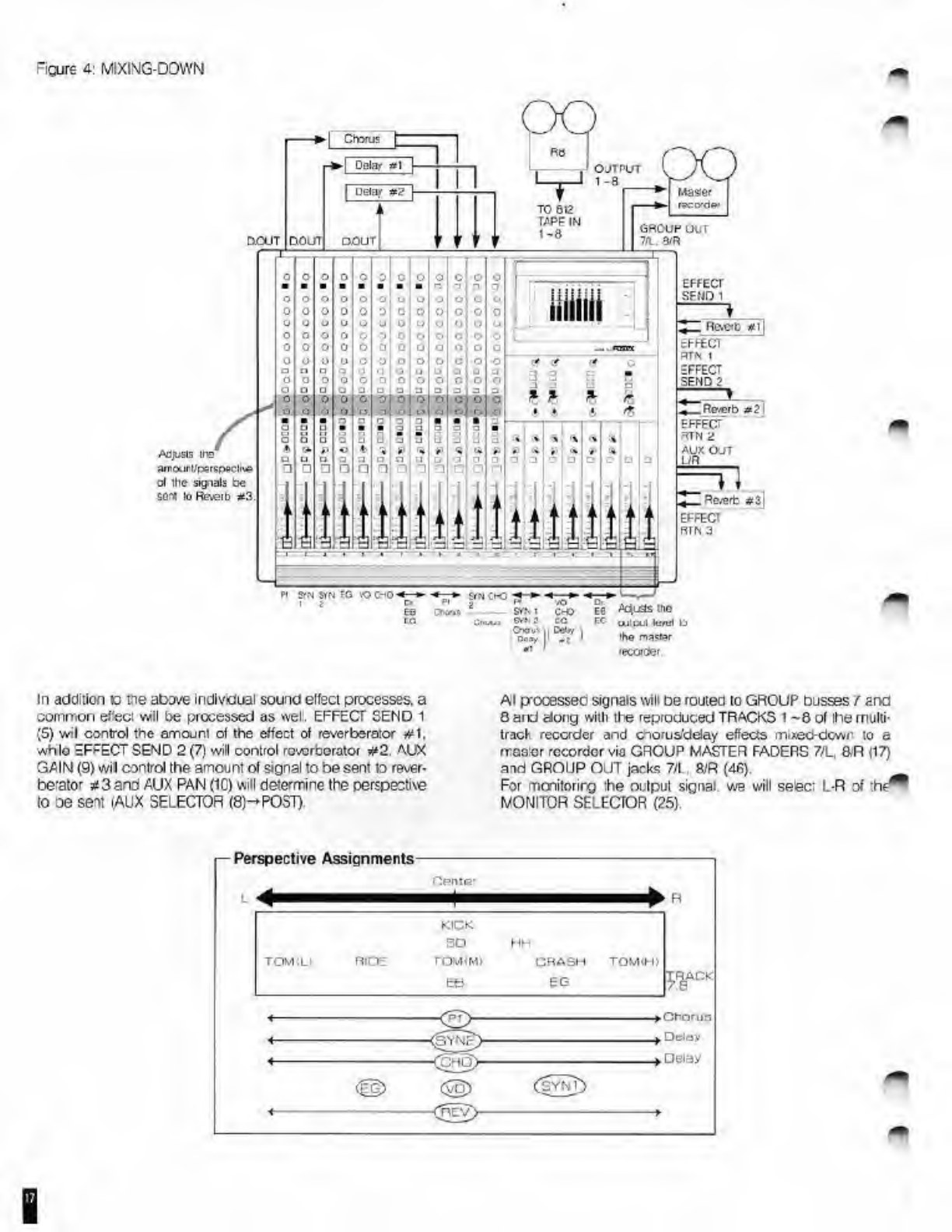
Figure
4:
MIXING-DOWN
Cfmis
OJTPUT
GROUP
Ui,'
7/L.
8/R
DCUT
DO
DOUT
EFFECT
SEMD
1
Rftdb
tt
l
-rrtCT
3TN
1
EFFECT
BEND
?
Reverb
=?
aojusis
me
arntxirUperspoctue
d
Ihc
signals
be
ser«
lo
Ftaerb
*3
Re^rt
*3)
-he
uilpul
kr'ul
1J
ihs
master
lecordii.
ST'S
i
O'
?
OwrtA
Ooa,
■
■
■
■
■
■
■
n
o
o
o
o
o
o
O
o
0
0
0
o
0
0
O
'J
o
u
o
<t
o
I
o
CJ
o
o
O
o
O
1
0
o
o
0
o
0
o
0
|
0
O
o
o
o
1}
o
o
o
o
o
tl
n
o
□
o
Q
u
LJ
In
addition
c
ne
abeve
Individual
sound
elfeci
processes,
a
common
effect
wil
be
processed
as
well.
EFFECT
SEND
1
(5)
wil
control
the
amojnt
ol
the
effect
of
reverberator
#1,
whlo
EFFECT
SEND
2
(7)
will
control
reverborator
#2.
AUX
GAIN
(9)
wil
control
the
amount
ol
signal
to
be
sent
to
rever¬
berator
*3
and
AUX
PAN
(1C)
will
determine
the
perspective
to
oe
sent
(AUX
SELECTOR
(8)-POST).
At
p-ocesseo
signals
will
be
routed
to
GROUP
busses
/
ana
0
aid
dong
with
tlie
reproduced
TRACKS
1
-8
of
Ihe
multi-
tract-
recorder
and
cnorua'delay
effects
mixed-down
to
a
maetor
recorder
via
GROUP
MASTER
FADERS
7/L,
SR
|17)
and
GROUP
OUT
jacks
7/L.
8,'R
(4fi)
For
monitorirg
;he
output
signal,
we
will
sefeci
L-R
of
MONITOR
SELECTOR
(25).

MIXING-DOWN
WITH
MIDI
EQUIPMENT
Here
we
will
ilustrale
a
mxing-down
situation
where
a
mUti-
track
recorder
and
a
MIDI
sequencer
will
syrchronze
thsir
play-oack
recording
and
SMPTE
time
record
SYNC
sgnal
on
ilie
edge
buck
of
an
rnullit/ack
lecorder.
change
the
sig¬
nal
to
a
M
Di
clock
by
using
an
interface
Look
at
Figure
5
This
configuration
r
lor
synnhmnbing
the
output
cf
a
MIDI
source
with
that
ot
an
R8
mutitrack
record¬
er
(TRACK
8~*SYNC
signal',
processing
various
sound
ef¬
fects
and
finaly
mixing-down
the
signals
to
GROUP
busses
7
and
8
Fust
the
post-FADER
signas
ot
:he
MIDI
sources
will
oe
routed
to
GROUP
MASTER
FADERS
5
and
6
(16)
via
the
GROJP
ASSIGN
SECTION
(11)
and
(12).
A
common
effect
(eHedor
#1)
will
then
be
processed
on
these
signals
using
EFFECT
SFND
1
(5)
The
processed
signals
will
then
be
rojted
to
GROUP
MASTER
FADERS
5
ard
6
(16)
with
the
Figure
5
MIXING
DOWN
with
MIDI
original
signals
via
the
RTN
1
ASSIGN
SECTION
(28)
Using
the
EFFECT
SEND
2
(7),
another
common
ef&c
(effector#2)
will
be
processed
on
the
npjt
signals
to
chan¬
nels
1
-7
(SEND
2
SELECTOR
(6)-AUX).
These
wit
be
grouped
to
GROU
3
MASTER
FADERS
3
and
^
(16)
via
the
RTN
2
ASSIGN
SECTION
(29).
The
output
of
TRACKS
‘
-7
will
oe
routed
to
AUX
GAIN
(9)
(AUX
SELECTOR
(8)-»TAPE).
In
order
to
group
the
mixed
signals
to
GROUP
MASTER
FACEFS
i
and
2
(16)
the
AUX
OUT
jack
(48)
wil
be
“patched"
fccnnected)
to
GROUP
BUSS
IN
jacks
1
and
2
(43).
To
recapitulate,
the
mixed
original
MIDI
signals
are
serl
to
GROUP
busses
1
and
2,
processed
signals
(effector
tt2)
to
busses
3
and
4,
a
combination
c
i
original
signals
and
processed
3gnal3
(effector
#1)
to
busses
5
and
6
From
here,
the
signals
are
sert
to
the
GROUP
TO
L
R
SEC
TION
(18)
and
(19)
and
mxed
down
o
a
master
recorder
f’cm
GROUP
MASTER
FADERS
7/_.
8/R
(17).
ouinu
S»NC
signal
wui
source
group
Maste
IQCfXCCX
sequence'
group
our
7.1.
am
Adiiststie
ameuter
e-eci
it
2
p'ococcoO
on
TRACKS
1
-7.
OJSS
IN
1.2
EFFECT
SEND
I
Fil^clci
*1
AdusTs
the
levetfpefspxnns
or
TRACKS
1
-
t
EFFECT
SENO
2
Eilecio-
n2
Arijists
the
ma«M
.Vliucs
IN>
irM*r
Arljutfstho
Arijisls
'he
nnhnl
output
level
ol
cwlpu:
revel
d
the
master
culpui
lewd
'a
ita
master
TRACKS
l-7
erector
is2
9gnais.
revel
or
the
recardH
Win
Muica
and
elfstlor
#1
agrals.
o
C
1
o
O
o|
c
O
n
n
n
n
r
'
1
n
r
O
C
c
O
o|
0
O
O
c
o
o
o
c
O
i*j
r
o
°
ol
O
O
0
c
Q
0
0
0
o
o
C
|
©
o
°
a
o
O
ji-j
c
OI
-
o
£
*
:
:
-
■
£
Tv
S
1
cl
S|
Si
S
sU
rs
-i
.
j
n
|
Q
□
Li
r
*
1
J

SECTION
9
TROUBLE
SHOOTING
Wion
tbo
unit
dooc
not
oporato
propory,
oleaee
check
tie
fol'owing.
Feedback
occurs
when
a
given
track
of
a
multitrack
recorder
is
set
to
input
monitor.
The
output
cr
the
given
track
may
be
comected
to
the
GROUP
buss
when
is
used
lor
the
output
ot
this
track,
this
wil
create
an
infinite
ocp
and
may
te
the
cause
ot
the
feedback.
No
signal
is
heard
at
the
INPUT
FADER
(15).
Yoj
may
have
connected
a
monaural
phore
plug
Vo
Ihe
INSERT
jack
(37).
"his
will
send
the
signal
to
the
effector,
but
will
not
return
the
signs
back
to
the
mi>sr.
Feedback
occurs
when
increasing
the
signal
level
with
EFFECT
SEND
1
(5),
EFFECT
SEND
2
(7)
andfor
AJX
GAIN
(9).
Ycu
may
have
connected
the
SENDS
o'
Hie
EFFECT
1.
EFFECT
2
and/cr
AUX
with
their
respective
INPUTS
tosses
(44)
and
(45).
creating
a
loop.
Cannot
process
an
effect
on
the
signal
to
AUX
GAIN
(9),
even
though
AUX
is
selected
with
the
SEND
2
SELECTOR
(6).
Ycu
may
haveseec’ed
POST
at
the
AUX
SELECTOR
(8).
The
SEND
2
SELECTOR
is
effective
only
when
the
AUX
SELEC¬
TOR
is
set
to
TARE
and
if
his
is
not
the
case
he
SEND
2
SELECTOR
is
laced
to
be
POST.
Cannot
hear
the
monitor
signal
selected
with
the
MONI¬
TOR
SELECTOR
(25).
Check
if
the
SOLO
LED
(33)
is
lit:
Ycu
msy
have
pressed
a
SOLO
SWITCH
somewhere
Adjust
the
MONITOR
LEVEL
knob
(26)
andtor
PHONES
VOLUME
(27).
No
sound
is
heard
when
a
SOLO
switch
(13)
and/or
(20)
is
pressed.
Adjust
tie
SOLO
LEVEL
knob
(24).
The
PEAK
LED
(1)
lights
frequently
ovon
aftor
adjusting
with
the
TRIM
(2).
Yoi
may
have
raised
the
gain
cf
the
EOUALI7FR
(4)
when
controlling
Ihe
tene
auaity.
causing
an
overload
al
the
ECXJALIZER
stage.
Sound
is
heard
at
GROUP
l/IASTER
FADERS
7/L,
8/P
(17)
even
though
no
assigning
is
done
to
group
busses
7
and
8.
You
may
have
raisec
the
GROUP
TO
L-R
GAIN
(18).
When
lot
in
usd
set
these
knobs
to
<*>.
Other manuals for 812
1
Other Fostex Music Mixer manuals


