Fostex VM200 User manual

VM200
Service Manual
Model
DIGITAL RECORDING MIXER

SAFETY INSTRUCTIONS
Read instructions - All the safety and operating instruc-
tions should be read before the appliance is operated.
Retain instructions - The safety and operating instructions
should be retained for future reference.
Heed warnings - All warnings on the appliance and in the
operating instructions should be adhered to.
Follow instructions - All operating and use instructions
should be followed.
Water and Moisture - The appliance should not be used
near water - for example, near a bathtub, washbowl,
kitchen sink, laundry tub, in a wet basement, or near a
swimming pool, and the like.
Carts and Stands - The appliance should be used only
with a cart or stand that is recommended by the manufac-
turer.
An appliance and cart combination should be moved with
care. Quick stops, excessive force, and uneven surfaces
may cause the appliance and cart combination to over-
turn.
Wall or Ceiling Mounting - The appliance should be
mounted to a wall or ceiling only as recommended by the
manufacturer.
Ventilation - The appliance should be situated so that its
location or position does not interfere with its proper ven-
tilation. For example, the appliance should not be situ-
ated on a bed, sofa, rug, or similar surface that may block
the ventilation openings; or, placed in a built-in installa-
tion, such as a bookcase or cabinet that may impede the
flow of air through the ventilation openings.
Heat - The appliance should be situated away from heat
sources such as radiators, heat registers, stoves, or other
appliances (including amplifiers) that produce heat.
Power Sources - The appliance should be connected to a
power supply only of the type described in the operating
instructions or as marked on the appliance.
Grounding or Polarization - The precautions that should
be taken so that the grounding or polarization means of
an appliance is not defeated.
Power Cord Protection - Power supply cords should be
routed so that they are not likely to be walked on or
pinched by items placed upon or against them, paying
particular attention to cords at plugs, convenience recep-
tacles, and the point where they exit from the appliance.
Cleaning - The appliance should be cleaned only as rec-
ommended by the manufacturer.
Nonuse Periods - The power cord of the appliance should
be unplugged from the outlet when left unused for a long
period of time.
Object and Liquid Entry - Care should be taken so that
objects do not fall and liquids are not spilled into the en-
closure through openings.
Damage requiring Service - The appliance should be ser-
viced by qualified service personnel when:
A.
B.
C.
D.
E.
Servicing - The user should not attempt to service the ap-
pliance beyond that described in the operating instruc-
tions. All other servicing should be referred to qualified
service personnel.
REFER SERVICING TO QUALIFIED SERVICE PERSONNEL.
CAUTION
RISK OF ELECTRIC SHOCK
DO NOT OPEN
CAUTION: TO REDUCE THE RISK OF ELECTRIC SHOCK,
DO NOT REMOVE COVER (OR BACK).
NO USER-SERVICEABLE PARTS INSIDE.
TO PREVENT ELECTRIC SHOCK, MATCH
WIDE BLADE OF PLUG TO WIDE SLOT,
FULLY INSERT.
POUR ÉVITER LES CHOCS ÉLECTRIQUES,
INTRODUIRE LA LAME LA PLUS LARGE DE
LA FICHE DANS LA BORNE CORRE-
SPONDANTE DE LA PRISE ET POUSSER
JUSQU' AU FOND.
CAUTION:
ATTENTION:
The exclamation point within an equilateral
triangle is intended to alert the user to the
presence of important operating and mainte-
nance (servicing) instructions in the literature
accompanying the appliance.
The lightening flash with arrowhead symbol,
within an equilateral triangle, is intended to
alert the user to the presence of uninsulated
“dangerous voltage” within the product's en-
closure that may be of sufficient magnitude to
constitute a risk of electric shock to persons.
“WARNING”
“TO REDUCE THE RISK OF FIRE OR ELECTRIC SHOCK,
DO NOT EXPOSE THIS APPLIANCE TO RAIN OR MOIS-
TURE.”
1.
2.
3.
4.
5.
6.
7.
8.
The power supply cord or the plug has been damaged;
or
Objects have fallen, or liquid has been spilled into the
appliance; or
The appliance has been exposed to rain; or
The appliance does not appear to operate normally or
exhibits a marked changed in performance; or
The appliance has been dropped, or the enclosure
damaged.
9.
10.
11.
12.
13.
14.
15.
16.
17.

VM200
3
Parts marked with this sign are safety critical components. They must always be replaced with identical
components. Refer to the Fostex Parts List and ensure exact replacement.
CAUTION
TABLE OF CONTENTS
1. SPECIFICATIONS . . . . . . . . . . . . . . . . . . . . . . . . . . . . . . . . . .
2. CONTROLS, INDICATORS & CONNECTORS . . . . . . . . . . . .
3. SOFTWARE UPDATE . . . . . . . . . . . . . . . . . . . . . . . . . . . .
4. UTILITY MODE . . . . . . . . . . . . . . . . . . . . . . . . . . . . . . . . . . .
5. EXPLODED VIEW, PCB ASSEMBLY & PARTS LIST . . . . . .
6. CIRCUIT DIAGRAMS . . . . . . . . . . . . . . . . . . . . . . . . . . . . .
Owner's manual : 8288433100 (for export model)
: 8288434100 (for domestic model)
Owner’s manual supplement : 8288671000 (for export model)
Service mode, error code list, exploded view, PCB assembly, parts list and circuit diagrams are given in this
manual to assist the service technician in maintaining the Model VM200.
NOTES
The following accessories are supplied with VM200 as the standard accessories.
*
*
Following is the packing material for the Model VM200.
*
Carton, inner, VM200 : 8228728000
Carton, outer, VM200 : 8228907000
Packing, side, L, VM200 : 8228453001
Packing, side, R, VM200 : 8228453002
Sheet, power cable : 8228462000
4
6
8
9
12
33

4
VM200
1. SPECIFICATIONS
DEFINITION
Specification Unit 0 dBV = 1 Vrms
Standard Input (Impedance)
MIC -60 dBV, -34 dBV (3 kΩor more)
LINE -10 dBV (10 kΩor more)
INSERT -10 dBV (20 kΩor more)
2TRACK IN -10 dBV (10 kΩor more)
EFFECT RETURN At 70 ~ 90 % position
DATA OUT
S/P DIF IN IEC 60958 (S/P DIF)
ADAT IN Alesis Proprietary Multi Channel Digital Interface
Standard Output (Impedance)
STEREO -10 dBV (10 kΩload or more)
MONITOR -10 dBV (10 kΩload or more)
AUX -10 dBV (10 kΩload or more)
REC BUSS -10 dBV (10 kΩload or more)
HEADPHONE 50 mW or more (33 Ωload)
STANDARD FADER POSITION
STEREO BUSS Set the INPUT / MASTER faders at “0” position when -10 dBV / 1 kHz
signal is fed to the INPUT (INSERT) jack (TRIM: MIN, PAN: L (R),
EQ: OFF).
MONITOR Set the MONITOR VR so that -10 dBV output is obtained at MONITOR
OUT when -10 dBV / 1 kHz signal is fed to the INPUT (INSERT) jack.
OUTPUT LEVEL
INPUT (1 ~ 8) →→
→→
→STEREO -10 dBV +2, -1 dB (Standard fader position)
INPUT (1 ~ 8) →→
→→
→MONITOR -10 dBV +2, -1 dB (Standard fader position)
FREQUENCY RESPONSE
INPUT →→
→→
→MONITOR OUT
Input: -60 dBV 20 ~ 20 kHz +1, -3 dB
Input: -10 dBV 20 ~ 20 kHz +1, -3 dB
INPUT →→
→→
→STEREO OUT
Output: -10 dBV 20 ~ 20 kHz +1, -3 dB
INPUT →→
→→
→PHONES
Output: 50 mW / 33 Ω50 ~ 20 kHz +1, -3 dB
EQUALIZER
HI / HI MID / LOW MID / LOW
+18 +18 dB ± 3 dB
-18 -18 dB ± 3 dB
S/N
Residual Noise
AUX 1 ~ 4 →→
→→
→ST BUSS OUT -88 dBV or less (All input / master faders: MIN)
-75 dBV or less (All input / master faders: At 0 dB)
MIC →→
→→
→INSERT -68 dBV or less (GAIN: MAX, PAD: OFF, Rs: 150Ω)
MONITOR OUT (VR: MIN) -100 dBV or less
PHONES -95 dBV or less (VR: MIN)

VM200
5
S/NCH IN →→
→→
→AUX 1 ~ 4, ST BUSS OUT
1 ~ 4 Ch (-4 dBV) 87 dBV or more (4 ChΣ: 82 dB or more )
1 ~ 4 Ch (-48 dBV) 70 dBV or more (4 ChΣ: 62 dB or more )
5 ~ 8 Ch (-4 dBV) 87 dBV or more (4 ChΣ: 82 dB or more )
5 ~ 8 Ch (-38 dBV) 76 dBV or more (4 ChΣ: 72 dB or more )
THD
CH IN →→
→→
→ST BUSS OUT 0.08 % or less (0 dBV output)
LINE IN →→
→→
→PHONES OUT 0.1 % or less (50 mW / 33 Ωoutput)
DYNAMIC RANGE
LINE IN →→
→→
→ST BUSS OUT 90 dB or more
CROSSTALK 68 dB or more (1 kH)
CLICK NOISE
Power On / Off -20 dBVp-p or less
Other switching (except +48 V SW) -30 dBVp-p or less
MIDI Operation check by Test Mode when connecting MIDI IN and OUT
WORD Operation check by Test Mode when connecting WORD IN and OUT
ADAT Operation check by Test Mode when connecting ADAT IN and OUT
S/P DIF Operation check by Test Mode when connecting S/P DIF IN and OUT
POWER CONSUMPTION 30 W
Specifications and appearance are subject to change without notice for product improvement.
6
VM200
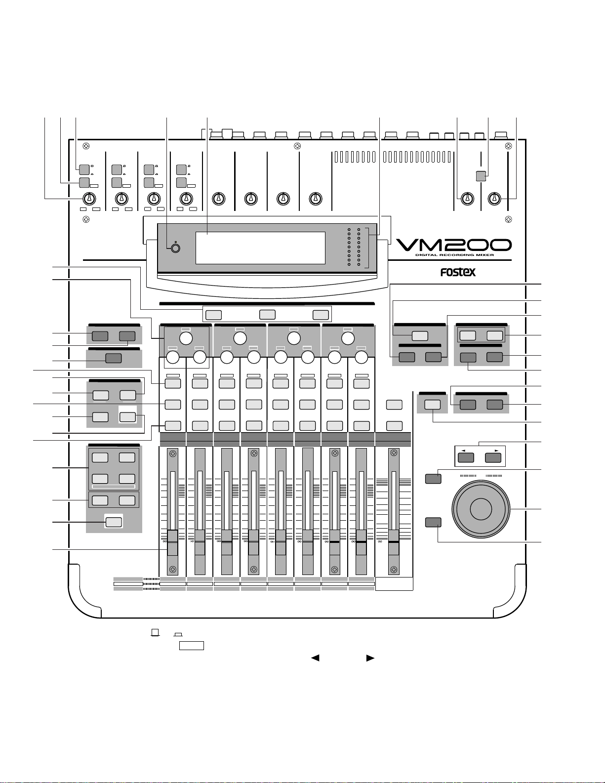
1. A/B Input Selectors [ A/ B]
2. PAD (26dB) switches [PAD/ 26dB ]
3. TRIM control [TRIM]
4. 2 TRK IN switch [2TRK IN]
5. Monitor Gain knob [MONITOR GAIN]
6. Phones Gain knob [PHONES GAIN]
7. Contrast dial
8. LCD Display
9. Meters [METER, ST BUSS/SOLO]
10. Data wheel [DATA]
11. /-1 and +1/ keys
12. ENTER key [ENTER]
13. EXIT key [EXIT]
14. SYSTEM key [SYSTEM]
15. MIDI key [MIDI]
16. Current Scene Status key [CURRENTSCENESTATUS]
2. CONTROLS, INDICATORS & CONNECTORS
Q
FREQ
GAIN
Q
FREQ
GAIN
Q
FREQ
GAIN
INPUT 4INPUT 3INPUT 2INPUT 1
PAD
26dB
A
B
PAD
26dB
A
B
PAD
26dB
A
B
PAD
26dB
A
B
-16 -60
+10 -34
-16 -60
+10 -34 -16 -60 -16 -60
TRIMTRIMTRIMTRIM
+10
0
-10
-20
-30
-40
-
+10
0
-10
-20
-30
-40
-
+10
0
-10
-20
-30
-40
-
+10
0
-10
-20
-30
-40
-
+10
0
-10
-20
-30
-40
-
+10
0
-10
-20
-30
-40
-
+10
0
-10
-20
-30
-40
-
16
PAN
Q
PAN
ON ON ON ON ON ON ON
SOLO SOLO SOLO SOLO SOLO SOLO SOLO
EQ EDIT EQ EDIT EQ EDIT EQ EDIT EQ EDIT EQ EDIT EQ EDIT EQ EDIT
SOLO
ON ON
SOLO
STORERECALL
EQ ON
STORERECALL
STORERECALL
SOLO
+1/
/-1
DATA
EXIT
ENTER
MASTER
15
1413
1211
10
9
1-8 ANALOG IN 9-16 ADAT IN 17-20 EFF RTN
AUX1 AUX2
AUX3 AUX4
EFF1 EFF2
ADD.AUX
TRIM
-10 -50
TRIM TRIM TRIM
-10 -50 -10 -50 -10 -50
INPUT 5 INPUT 6 INPUT 7 INPUT 8
MIN MAX
GAIN
MAXMIN
GAIN
2TRK IN
PHONESMONITOR
+10
0
-10
-20
-30
-40
-
ADAT IN
0
-10
-20
-30
-60
-
-40
PANPANPANPANPANPAN
-40
-36
-24
-18
-12
-9
-6
-3
OL
ST BUSS/SOLO
LR
METER
+10 -34 +10 -34
CHANNEL
FADER MODE
KEY MODE
METER
CHANNEL/
CH VIEW
PHASE GROUP
ROUTING/ PAIR/
MMC SEND
CURRENT SCENE STATUS
SETUP
SYSTEM MIDI
EQ/LO EQ/LO-MID EQ/HI-MID EQ/HI-MID
FREQ
GAIN
EFF EDIT
EFF 2EFF 1
EQ LIBRARY EFF LIBRARY
SELECTED EQ
SCENE MEMORY
REC BUSS
8
7
6
5
4
2020
1 2 3
1919
1818
1717
ANALOG INANALOG IN
EFF REFF RTNTN
PAGE SELECT
123 4 6587 9
11
12
13
14
15
16
17
18
19
20
21
22
23
24
25
26
27
29
28
30
31
32
33
34
35
36
37
38
<TOP PANEL >
10
VM200
7
17. ROUTING/PHASE key [ROUTING/PHASE]
18. PAIR/GROUP key [PAIR/GROUP]
19. CH VIEW key [CH VIEW]
20. CHANNEL/METER key [CHANNEL/METER]
21. AUX1~ 4 keys [AUX1, AUX2, AUX3 AUX4]
22. EFF1 ~ 2 key [EFF1, EFF2]
23. CHANNEL key [CHANNEL]
24. EQ ON key [EQ ON]
25. EQ LIBRARY RECALL key [RECALL]
26. EQ LIBRARY STORE key [STORE]
27. EFF1 ~ 2 keys [EFF1, EFF2]
28. EFF LIBRARY RECALL key [RECALL]
29. EFF LIBRARY STORE key [STORE]
30. REC BUSS SOLO key [SOLO]
31. SCENE MEMORY RECALL key [RECALL]
32. SCENE MEMORY STORE key [STORE]
33. Faders
34. ON key [ON]
35. SOLO key [SOLO]
36. EQ EDIT key [ EQ EDIT ]
37. EQ Section Rotary Controls [GAIN, FREQ /PAN,
Q /PAN]
38. Page Select keys [1-8 ANALOG IN, 9-16 ADAT IN,
17-20 EFF RTN]
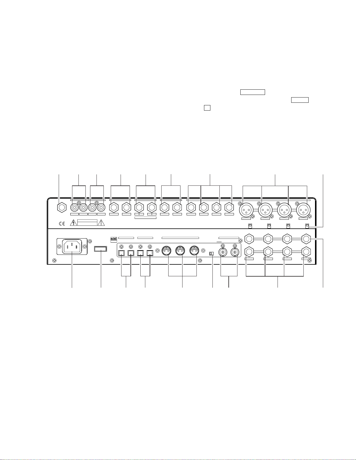
1. PHONES [PHONES] (Phone jack)
2. MONITOR OUT [MONITOR OUT] (RCA jack)
3. 2 TRK IN [2TRK IN] (RCA jack)
4. ST BUSS OUT [ST BUSS OUT] (Phone jack)
5. REC BUSS OUT [REC BUSS OUT] (Phone jack)
6. AUX SEND [AUX SEND] (Phone jack)
7. Inputs 1 ~ 4: A, B [A, B] (A: XLR, B: Stereo phone jack)
8. +48V Phantom Power [+48V ON/OFF]
9. Inputs 5 ~ 8 (Phone jack)
10. Inserts 1 ~ 4 [INSERT] (Stereo phone jack)
11. AC Inlet [AC IN]
12. Power switch [POWER]
13. ADAT IN & OUT [ADAT IN/OUT] (Optical)
14. S/P DIF IN & OUT [S/P DIF IN/OUT] (Optical)
15. MIDI In/Out/Thru [MIDI IN/OUT/THRU] (MIDI)
16. 75ΩOn/Off switch [75ΩON/OFF]
17. WORD IN/OUT [WORD IN/OUT] (BNC)
CAUTION
RISK OF ELECTRIC SHOCK
DO NOT OPEN
AVIS:
WARNING:
RLRLRLR4L3218765
1234
AAA
1234
+48V OFF
ON +48V OFF
ON +48V OFF
ON +48V OFF
ON
PHONES
OPTICAL
WORD
OUTIN
AC IN
POWER
S/P DIFADAT
IN OUTOUTIN
MIDI
IN OUT THRU 75Ω
OFFON
INPUT
INSERT
B
INSERTINSERT
BB
ADD.AUX SEND
AUX SENDST BUSS OUT2TRK IN
MONITOR OUT REC BUSS OUT
TO REDUCE THE RISK OF FIRE OR ELECTRIC
SHOCK, DO NOT EXPOSE THIS EQUIPMENT
TO RAIN OR MOISTURE.
RISQUE DE CHOC ELECTRIQUE NE PAS OUVRIR
95 62 3 41 7 8
71015 16 1714131211
<REAR PANEL >

8
VM200
3. SOFTWARE UPDATE
In order to update the VM200 software, the ROM CARD PCB (P/N:
8274219000) must be required. Mount the updated software (2 pcs.
EPROMs) into the EPROM sockets (U1 and U2) on the PCB. When
updating the software, make sure that the switch SW1 on the ROM CARD
PCB is set to “EPROM” side.
3-1. Preparation
3-2. Procedures
Turn the data wheel and select the menu “004 Program_Flash_ROM”.
Press the ENTER key. The VM200 starts transferring the program data
from the EPROM into the flash ROM on the MAIN PCB. The following
is the LCD display while updating the software inside the flash ROM.
Loosen 4 x screws (BBT3 x 8 BZn) and remove 2 pcs. ROM Cover (P/N:
8221142000) on the VM200 bottom panel.
1)
Plug the ROM CARD PCB into the J18 connector on the MAIN PCB
Assy. When plugging the ROM CARD PCB, check if the EPROMs are
facing the bottom side.
2)
Turn on the power of VM200. On condition that the ROM CARD PCB
is correctly plugged in, the LCD display indicates the following.
3)
4)
After transferring the software is completed, the following is displayed
on the LCD display.
Press the ENTER key. The following is displayed on the LCD display.5)
8251984 001
U2
C9
1J1 49
250
C8
EPROM
FLASH
SW1
TP2
NMI
TP1
TP3
U1
/RST
DGND
M27C2001
-10F1 M27C2001
-10F1
ROM CARD PCBTOPVIEW
SME
16V
10uF
SME
16V
10uF
(M)85˚C (M)85˚
VM200 BOTTOM PANEL
FRONT side
REAR side
VM200 BOTTOM PANEL
MAIN PCB
FRONT side
REAR side
Connector J18
(50-pin)
ROM CARD
PCB
EPROM/FLASH
SW
ROM COVER

VM200
9
Press either the ENTER or EXIT key. The VM200 returns to the initial mix mode display.6)
Once turn off the power of VM200 and disconnect the ROM CARD PCB. Then, turn the power back on again. Next, put
the VM200 into the Utility Mode by pressing the EXIT key while holding down the /-1 and +1/ keys. Then, select the
menu “002 Version_Disp.”
7)
Press the ENTER key. Confirm that the flash ROM is correctly updated. The LCD display below indicates that the
software version number is “V01.02” and its programming date is “990621 (June 21, 1999)”.
8)
4. UTILITY MODE
There are various Utility Modes available in the VM200. Please utilize them when servicing the unit.
The way of putting the VM200 into Utility Mode is as follow.
4-1. Putting VM200 into Utility Mode
Turn on the power of VM200. The normal Init Mix display appears after the Fostex and VM200 banner scroll.
1)
While holding down the EXIT key, press the /-1 and +1/ keys. If the VM200 is correctly put into the Utility Mode,
the following appears on the LCD display.
2)
Rotate the data wheel to select a desired Utility Mode and press the ENTER key to execute. To exit from the Utility Mode,
press either the ENTER or EXIT key in the above display condition.

10
VM200
4-2. 002 Version Disp.
Please refer to the section “3-2. Procedures 7) and 8)” on page 9.
4-3. 003 Erase All Flash ROM.
This mode is prepared in case wrong data is somehow programmed into the Flash ROM. Please remember that the ROM
CARD PCB must be plugged into the J18 (50-pin) connector on the MAIN PCB, so that all the data in the Flash ROM can
be erased.
4-4. 004 Program Flash ROM.
Please refer to the section “3. SOFTWARE UPDATE” on page 8 ~ 9.
4-5. 005 Fader Demo On/Off.
This Utility Mode is prepared to demonstrate the movement of 9 motorized faders. By turning on this mode (pressing the
ENTER key), these faders start moving in the shape of sine wave. The LCD display returns to the initial mix display by
pressing the EXIT key while the faders are moving. To quit, press the ENTER key again when the “005 Fader Demo
On/Off.” is selected.
4-6. 006 All LED Demo On/Off.
This Utility Mode checks if all the self-illuminating switches on the top panel as well as the LEDs used for stereo buss/
solo meters are correctly working. To turn them on, press the ENTER key. To turn off, press the ENTER key again.
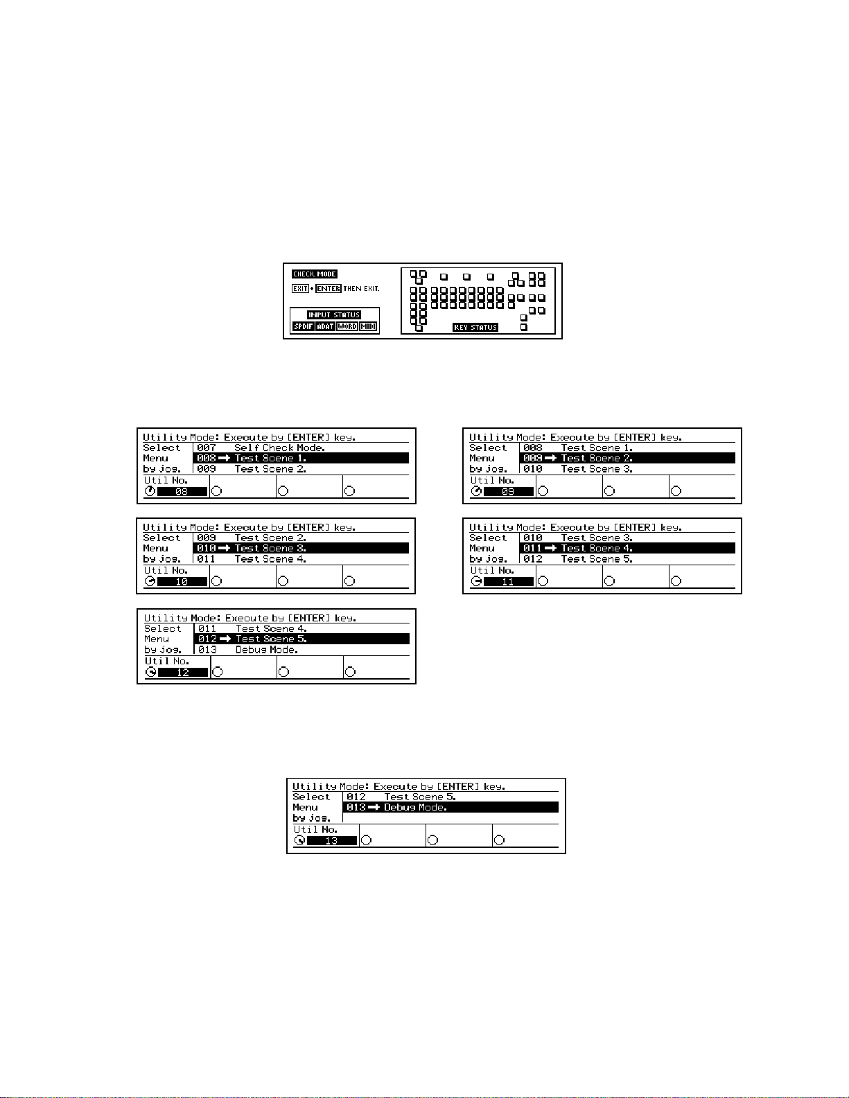
4-7. 007 Self Check Mode.
Before putting the VM200 into the Self Check Mode, connect the following terminal.
CAUTION
RISK OF ELECTRIC SHOCK
DO NOT OPEN
AVIS:
WARNING:
RLRLRLR4L3218765
1234
AAA
1234
+48V OFF
ON +48V OFF
ON +48V OFF
ON +48V OFF
ON
PHONES
OPTICAL
WORD
OUTIN
AC IN
POWER
S/P DIFADAT
IN OUTOUTIN
MIDI
IN OUT THRU 75Ω
OFFON
INPUT
INSERT
B
INSERTINSERT
BB
ADD.AUX SEND
AUX SENDST BUSS OUT2TRK IN
MONITOR OUT REC BUSS OUT
TO REDUCE THE RISK OF FIRE OR ELECTRIC
SHOCK, DO NOT EXPOSE THIS EQUIPMENT
TO RAIN OR MOISTURE.
RISQUE DE CHOC ELECTRIQUE NE PAS OUVRIR
OPTICAL
CABLE OPTICAL
CABLE MIDI
CABLE BNC
CABLE
MIDI IN ↔OUT
S/P DIF IN ↔OUT
ADAT IN ↔OUT
WORD IN ↔OUT
VM200
11
This mode checks the following points.
• Input status of MIDI , S/P DIF, ADAT and WORD circuitry.
If the above mentioned cable is not properly connected or something is wrong with a circuitry, indicators are light empty.
Otherwise, indicators are highlighted, which means that the circuitry is working correctly. The drawing below indicates
that the S/P DIF and ADAT circuitry are working correctly but something is wrong on the WORD and MIDI circuitry or
the cable is not properly connected.
• Self-illuminating switches on the top panel
When pushing the key on the top panel, the corresponding square icon turns highlighted. If not, switch is not working
correctly.
4-8. 008 ~ 012 Test Scene 1 ~ 5.
The Test Scenes 1 ~ 5 have nothing to do with servicing the VM200. This is exclusively designed for production purpose.
4-9. 0013 Debug Mode.
This mode has nothing to do with servicing the VM200.

12
VM200
VM200 OVERALL EXPLODED VIEW
7. EXPLODED VIEW, PCB ASSEMBLY & PARTS LIST
Ref. No. Part No. Description
1 8221 2792 00 Panel, top, VM200
2 8221 2820 00 Bracket, PCB, A, VM200
3 8221 2830 00 Bracket, PCB, B, VM200
4 8221 2840 00 Bracket, PCB, C, VM200
5 8221 2811 00 Panel, rear, VM200
6 8212 6590 01 Pad, side, L, VM200
7 8212 6590 02 Pad, side, R, VM200
8 8274 2060 00 PCB assy, Key, VM200
9 8274 1900 00 PCB assy, Fader, VM200
10 8221 2860 01 Bracket, fader, VM200, A
11 8221 2860 02 Bracket, fader, VM200, B
12 8274 1920 00 PCB assy, Ana-In, VM200
13 8207 0061 02 Spacer, MPS-04
14 8245 3400 00 Nut, phone jack
15 8216 7100 00 Shield, Ana-in, VM200
16 8274 2170 00 PCB assy, Regulator, VM200
17 8207 0117 01 Cord holder, CS-1-U
18 8207 0117 04 Cord holder, CS-4-U
19 8212 6600 00 Panel, LCD, VM200
20 8212 6610 00 Window, LCD, VM200
21 8221 2850 00 Bracket, LCD, VM200
22 8207 0047 01 Plastic rivet, #1C18
23 8216 6980 00 Shield, LCD, VM200
24 N/A
25 8212 6620 00 Plate, reflect, LCD, VM200
26 8204 0370 01 Ring, CSTW-2
27 8216 7080 00 Sheet, LCD, VM200
28 8274 2050 00 PCB assy, LED Meter, VM200
29 8260 5640 00 LCD assy, VM200
30 8216 7110 00 Sheet, side, LCD, VM200
31 8216 7150 00 Sheet, meter, LCD, VM200
32 8221 2800 00 Panel, bottom, VM200
33 8274 1840 00 PCB assy, Main, VM200
34 8274 1860 00 PCB assy, Power, VM200
35 8221 2610 00 Bracket, AC-In, FD-8/VM200
36 8207 0120 00 Foot, FF-822
37 8221 1420 00 Cover, ROM, DMT-8/VM200
38 8226 1430 06 Knob, VR, D, NW
39 8226 2470 01 Knob, encoder
40 8226 2380 00 Knob, jog, FD-4/8/VM200
41 8226 2480 01 Knob, sw
42 8226 2490 01 Knob, fader, N
43 8226 2490 02 Knob, fader, R
44 8226 2460 01 Button, 7 x 13, LED
45 8226 2460 02 Button, 7 x 13, N4.5
46 8326 0130 03 Button, push, N08
47 8216 7090 00 Cover, isolation, VM200
48 8221 2931 00 Shield, power, VM200
49 8207 0009 10 Stay, PCB, support, KGLS-22S
50 8274 2181 00 PCB assy, Power-Fader
Ref. No. Part No. Description
51 8216 7130 00 Sheet, bottom, VM200
52 8276 8000 00 Cord, power, VM1292-1298, JPN
8276 8010 00 Cord, power, VM0033-0089,
USA/CND
8276 8021 00 Cord, power, CEE, 031013, EUR
8276 9170 00 Cord, power, BS, 3C, KP610-KS31A,
UK
53 8274 1910 00 PCB assy, Jog, VM200
54 8274 1930 00 PCB assy, Ana-Out, VM200
55 8216 6970 00 Shield, Ana, VM200
56 8274 1850 00 PCB assy, LCD Back, VM200

VM200
13
VM200 OVERALL EXPLODED VIEW
1
B3 x 6BZn
2
3
4
B3 x 6BZn
BBT3 x 6BZn
5
BBT3 x 8BZn
7
6
BBT3 x 8
BZn
BBT3 x 8BZn
8
9
10
11
12
14
13
15
16
BBT3 x 6BZn
17
20
19
21
22
23
25
26
BBT3 x 6BZn
27
28
29
30
31
32
33
34
35
36
37
39
40
41
41
38
43
42
4545 45
45
44
44
4545
4544
4546
4547
4548
4549
4550
4551
4552
F3 x 5 CZn
F3 x 5 CZn
BBT3 x 6BZn
38
38
BTT4 x 8
BZn
18
BBT3 x 6
BZn
THW
3 x 6 x 0.5
THW3 x 6 x 0.5
BBT3 x 6BZn
BBT3 x 8BZn
B3 x 6BZn
BBT3 x 8CZn
BBT
3 x 6
BZn
BBT3 x 6BZn
BBT3 x 6BZn
BBT3 x 6BZn
BBT3 x 8BZn
BBT3 x 6BZn
BBT3 x 6BZn
BBT3 x 6BZn
BBT3 x 6BZn
BBT3 x 6
BZn
BBT3 x 6BZn
BBT3 x 6BZn
53
BBT3 x 6
BZn
BBT3 x 8BZn
BBT3 x 8BZn
BBT3 x 6BZn
BBT3 x 6BZn
2
56
54
55
18
18
LW4
BTT4 x 8BZn
BTT4 x 8BZn
BBT3 x 6BZn
30
21
14
VM200
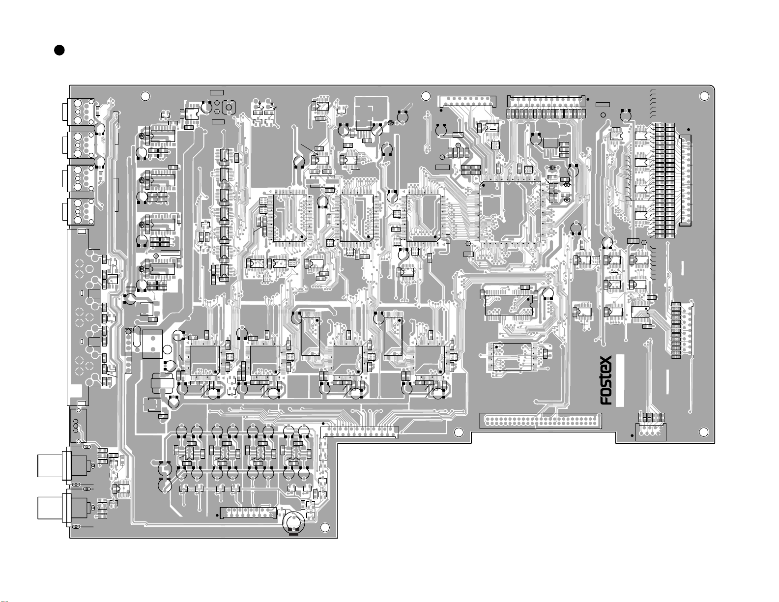
VM200 PCB PATTERN DRAWING
• Parts Side of MAIN PCB
8251986 101
R213
R216
L2
D1
U12
U13
R321
R335
8
1
U202
R336
L201
R232
C232
L202
D202
D201
D203
R233
R214
U14
S201
ON TERM
J201
WORD IN
J202
WORD IN
OFF
MIDI
OUT
MIDI
IN
R1
L4L6
L5
R6
R7
R5R4 L2
J203
IN
OUT
ADAT
U629
OU2 OU1
OR1OR1
R253
R254
R255
R8
R256
C257
C252
C251
C34
C1
R110
R234
R332
R304
C205
C304
R312
U102
R301
R302 R306
C319
R331
U304 C9
R101
U101
C2
C301
C201
C7
C314
C55
C41
C101
C103
C81
R102
C141
L10
5
U15
R9
C701
U251
1
1
9
SPDIFT
IN
OUT
J205
C209
C23
R702
C24
1 U701
8
1
15
U16
U3
15
U7
X1
R33 R32
R43
R44
R45
TB20
TB21
TB22
TB23
TB24
TB25
TB26
TB27
TB28
TB29
TB30
TB31
TB32
TB33
TB34
TB35
TB36
TB37
R172
R173
R174
R175
R176
R177
R178
R179
R180
R181
R182
C158
C159
C160
C161
C162
C163
C164
C165
C166
C167
C168
C169
C170
C171
C172
C173
C174
C181
C182
R183
R184
R185
R186
R187
R188
R193
R194
C151
C152
C153
C154
C155
C156
C157
R165
R166
R167
R168
R169
R170
R171
TB13
TB12
TB11
TB10
TB9
TB8
TB7
TB6
TB5
TB4
TB3
TB2
TB1
TB14
TB15
TB16
TB17
TB18
TB19
PCB. MAIN.VM200
L11
L12
R31
C66
C67
C68
U1
8
C341
1
X2
U201
8
C102
1
8R34
R35 R40
R41 R36
R11
1
9
1
8
C710 60
70
80
1
9
50 40
30
20
10
1
10090
U301
60
70
80
50 40
30
20
10
1
10090
U302 U21
60
70
80
50 40
30 10
20
30
40
50 110
120
130
140
150
160170180190200
60
148
24 25
70 80 90 100
1
20
10
1
10090
1U707
8
C707
C708
U709
1U704
8
C708
1U705
8
C709
C706
U401
R401
1U706
R707
R706
R201R202
R217
R218
C401
1
9
U402
C402
1
9
U403
C403
1
8
C104
R402
R219
R303
R315
R311
R109
C318
C73
C72
C69
R12
C37
R37
R39
R38
R21
C311
R305
8
R404
R403
1U703
8
C705
1U702
9
C253
L251
R263
R264
R265
R266
C257
C262
C261
U261
1
9
C263
L251
R522
R521
R523
C267
C542
C541
U503
C12
C11
C510
C503
C504
C516 C515
U621
U622
U612
C4
C3
U611 U614 U613 U618 U617
U627
C607C608C605C606C603C604C601C602
1
5
C642
C641
C632
C631
1
5
C644
C643
C634
U602
U601 C633
1
5
C646
C645
C636
U603 C635
1
5
C648
C647
C638
U604 C637
C627C628C625C626C623C624C621C622
U623
U628
U625
U601
U626
D2 C15 U624
C521
C530
C561
U553
C527
C501
C5
C10
C16
L13
U501
R504
C508
R514
R501
C531
C512
C528
R511
C532
R512
R515
C513
C505
C523
C524
C536 C535
C525
R653
R654
R505 C511
R91 50 40 30
20
10
1
70
60
80 90 100
U502
50 40 30
1
17
C581
U554
1
17
20
10
1
70
60
80 90 100
C567
R567
C562
R563
C572
R573
R561
C569
C570
C576 C575
J17
TO ANALOG IN
125
J12
TO FADER 1
25
J14
TO KEY
1
30
J15
TO LCD
J11
TO KEY
18
17
1
J16
TO ANALOG OUT
117
J13
TO FADER
117
J18
TO EPROM BOARD
2
149
50
C595
C571
U551
50 40 30
20
10
1
70
60
80 90 100
C587
R587
C582
R583
C592
R593
R581
C589
C590
C596
C591
U552
50 40 30
20
10
1
70
60
80 90 100
R92
W1
TO POWER 18
C507
C6 U5
U4
1
9
C543
C333
L501
R322
TP8
R321
R323
C336
C332
C331
U303
1
9
L301
R524
C702 R704
R324
C208
J204
J206
J1
LOCK384
TP2
OLD2
LOCK2
S1
RESET OLD1
LOCK1
TP1
/RST
TP6
/WRDY
TP3
/NMI
DGND
TP7
DGND
TP5
CKIO
TP4
/RD
U11 U155 1
8
U151
1
8
U152
1
8
U153
1
8
9
1
U154
U19
C35
9
1U17
C88
C84
9
1
1111525
26 36 40 50
U32
U31
U33
C20
8
1U20
C36
C85
C87
8
1U18
C38
8
1
1
13
U23 C18
C86
C19
C105
8
1
U103

VM200
15
• Foil Side of MAIN PCB
R141R144R147R150R153R156R159R162
R10
C14 C40
C39
R106
C910
C585
C583
C584
C909
C585
C563
C564
C565
C908
C913
R617R627
R655
R652
R637
R647
R13 R648
R638
C911 R618
R608
R628
C618
R617R627
R613C623
R611C621 R614R624
R612R622
R604C614
R602C612
R616R626
R606C616
C912
C595 C575 C535 C515
R107 C70
C53
C90
R46
C51C50
C49
C48
C47
C46 C45 C44
C43
C42
C316
C313
C315
C306
C307
C302
C308
C311
C312
C305
C309
R307
R222
C202
C221
C206
C203
C704C703
R703
C509
C529
C907
C577
R705
R220
R221
C321 C343
C342
C207
C204
C904
L251
C251
R257
C255
C254
C210
C212C213
C209C208 R212
R211
C211
R215
R214
J203
J205
J204
J206
C256
R252
R251
C905C906
C903
C22
R2
R3
C334
C335
C544
C902 C901
W1
18
C545
L261
C261
L301
L501
C331
C541
C527
C561
C521
C501
S201
J201
J202
R91
R92
J1
C5
C4C3
C567
R418
C607
C15
C608
C628
C617
R607
C615
R605
C613
R603
C611
R601
C627
R633
R643
R644
R634
C624
C623
R631
R641
R642
R632
C622
C621
R635
R636 C625
C626
C605
C606
C603
C604
C601
C602
C414
R417
R416
C413
R415
R414
R412
R413
R412
C411
R411
C6
C507
C16
R267
C265
C264
C266
R262
R261
C322
C303
C317
C54
X1
C71
R47
C52
C65
C64 C61
C13
C62C63
C103
C104
C81
C41
C587
C581
C55
C314
C7
C2
C304
C1
C34
S1
C301
C201
C205
C141
L12
L11
L10
R651 R108
R105
R426
R422
C416
R421
R420
C415
R419
C418
R425
R424
C417
R423
R104
R103
R143R146R149R152R155R158R161R164R192 R142R145
C142C143C144C154
TP5
TP7
TP3
TP6
TP1
TP2
TP8
TP4
C146
C25
C26
C27
C28
C29
C30
C31
C32
C33
R148R151R154R157R160R163R191
J14
1
30
117
J15
1
17
251 J13J12
1
17
25 1
J16
J17
81
50
49
40
39
30
29
20
19
10
9
2
1
J11
J18
OLED1
OLED2
16
VM200
• KEY PCB
8251979 202
R943
C304
R916
X101
J301
R911
R912
R913
R918
R917
R916
S101 D111
S100 D110
R331
R332
R333
R334
R335
S102 D112
S200 D210
D216
D200
S300 D310
D300
S201 D211
D201
S400 D410
D400
S203 D213
D203
S204 D214
D204
S401 D411
D401
S500 D510
D500
S600 D610
D600
S402 D412
D402
S501 D511
D501
S601 D611
D601
S403 D413
D403
S502 D512
D502
S602 D612
D602
S404 D414
D404
S503 D513
D503
S603 D613
D603
S405 D415
D405
S504 D514
D504
S604 D614
D604
S406 D416
D406
S505 D515
D505
S605 D615
D605
S407 D417
D407
S506 D516
D506
S606 D616
D606
S507 D517
D710
D814
D815
D812
D813
D811
D810
D713
D714
D712
D716
D715
D711
D717
D507
S607 D617
D607
S707
D703
S706
D702
S705
S702 S701
S605S700 S604
S803
S801
S800
S802
D701
S704 S703
D700
S202 D212
D202
S301 D311
D301
S302 D312
D302
S303 D313
D303
S304 D314
D304
S305 D315
D305
S307 D317
D307
S306 D306
D306
S207 D217
D207
S205 D215
D205
S206
D206
R914
R314
R313
R312
R311
R411
R412
R413
R415
R416
R417
R418
R414
R915
TO MAIN
1
8
C305 C302 C101
U101
PCB. KEY. VM200
R301
R315
R516
R517 BE
BE
BE
R518
R326
R321
R511
R512
R513
R514
R515
R322
R323
R324
R325 Q305 U703 U701 U603 U601 503
U702 U602
U501 U403 U401
W309
TO POWER
TO MAINLED-METER
1
4
W102
3
1
U502 U402
J303
17
30
1
J305 1
Q302
Q301
Q303
Q304
Q308
Q307
Q306
BE
BE
BE
B
B
E
E
R327
R328
R336
R337
R338
R302
VM200
17
• ANA IN PCB • FADER PCB
• Parts side of POWER FADER PCB • Foil side of POWER FADER PCB
8251986 102
W2
W1
U4
D2
C1
U3 D1 T1
C8
D3
C12 R7 C9 C10
1
D
S
C
4
31
1
1
U2
D4
C2
U1
U5
PCB. POWER FADER. VM200
U22
C4 C3
C30
L1
J3
J1
2
U5
D4
C10 C9
T1
U1 U2
D10
L1
1
J1
J3
C22
C3
R30
C30
R5
R3
R8
R6
C5
R4
C11
C4
C2
D1
D3
D2
U4
W2
W1
1
U3
C8
R7
C12
C1
C6
R2
R1
C7
C21
C20
8251976 101
J102
R951
R181 R196
C135
C899
C889
C121
C111
R117 R124
C101
C106
C140
R115
C114
PCB. ANA-IN.VM200
C113
D201
D102
C103
C105
C136
R879
C161
C151
R869
R191
R182
R192
R130
R131
R104
R114
C139
D202
D101
R112
R899
R889
C131
C123
R125 R211
R127
C201
R2
R1
61
C132
C126
C122
C124
R129
C202
C125
R123
J111 J103
L997 L996
J101
L999
C133 C134
R210
C137
R126 R128
C143
C138
L998
C191C181
R101
R111
R102
R112
R107 C107
C115
R116
R106
R181
C112
C104
R105
R151
C102
JS901
S101
S102
R171
R113 R998
R103
R121
R999
8251977 202
45
67
132
91 C401
U401
R401
C413
C411
MOTOR
U411
45
67
132
91 C402
U402
R402
MOTOR
U412
45
67
132
91 C403
U403
R403
MOTOR
U413
45
67
132
91
C404
U404
R404
MOTOR
U414
45
67
132
91 C405
U405
R405
MOTOR
U415
45
67
132
91 C406
U406
R406
MOTOR
U416
45
67
132
91
C407
U407
R407
MOTOR
U417
45
67
132
91 C408
U408
R408
MOTOR
U418
45
67
132
91
C409
U409
R409
MOTOR
U419
C414
C414
W401
J401
TO MAIN TO POWER
51
1125
17
J402
TO MAIN
PCB. FADER. VM200

18
VM200
• ANA OUT PCB
• JOG PCB • LED METER PCB • REGULATOR PCB
• LCD BACK PCB
1
W901
U901
PCB, JOG.VM200
8251979 003
3
8251979 004
J101
PCB
LED-METER
VM200
117
D607 D606
D807 D107
D806 D106
D805 D105
D804 D104
D803 D103
D802 D102
D801 D101
D800 D100
C101
1
4W101
C102
C103
8251979005
U101
8251976 102
54
31
11
J101
TO LCD-IF
R101
L101 L102
12
W102
TO POWER
PCB. LCD-BACK.VM200
8251977 101
TO POWER
L999
L998
W901 J961J962
FROM MAIN (ANA-IN) TO MAIN (ANA-OUT)
PCB. ANA-OUT.VM200
17 1125
R981
R915 C909
C961
R964
R962
R931
C627
R985
934
R945
S101
R946 R935
R936
C954C964
R963
R951
R953
R966
R956
C951
C921
C922 R942
R932 R933
C932
R913 R903
R944
C943
C931
C912
C7
C941
C6
R954
R983
C981 C991
R965
BE
BE
C965
C962
Q961
R986
C5
C628
C952
C955
U951
R955
R967
J907
J911
J902
J901
J906
J905
J904
J903
J801
J701
J601
J501
J913 R957
C944
R947
R952
C810 C808
C20
R1
C17
R2
C811
U901
C803
R810
R812
R806 R706 R606 R506
R510
C703
R809
R709 R710
C708 R708
R712
C702
C603
C510
C503
C502
C501
C602
C601
C701
R707
C711 C807
C601
C611
R610
R612
R609
R512
R603
C509
C607
C606
C511
C801
C802
C706 C707
R803
R802
R703
R811
R711
C709
C806
R704
R705
R702
C15
C608
C609
R604
R602 C11
C8
R605
R511
R509
R507
R508
R504
R503
C507
C506
R505
C508
R607
R608
C14
R804
R805
C9
C12
C710
R808
R807
C16
C911
C809
C910
R801
R701
R601
R501
Q951
R921
R922
BE
BE
Q941
Q931
R937 R943
C942
W401
61
W301
61
W201
61
W101
61
R934
C933
71

VM200
19
• POWER PCB
• Parts side of LCD-IF PCB
• Foil side of LCD-IF PCB
L4
C3
C8
D9 R8
C29
C7
R1 R9
3
41
2
U3
R4 R6
R22
C4 C13
L3
C14
C12
R21
D6
C18
C16
C24
C15 C17
U6
C26
D10
D2
D4
D5
R3
R20
R2 R5
C41
C28 C10
W101
to reg
14
U4
R7
C9
J1 J3
C40
A–15
AGND
AGND
A+15
DGND
DGND
D+5
A–15
AGND
A+15
DGND
AGND
AGND
+48
D+5
DGND
D+5
D+5
DGND
DGND
1
17
81
1
to ANALOG to MAIN
C27
R10
R11
J6
J4 to L. C. D.
to KEY
U2
C21 C22
C6
D1
C20
D9
U5
D
S
C
14
3
L5
J2 C2 C1
2
14
3
2
L2
L1
U1
F1
S1
W2
W3
L
N
PCB. POWER. VM200
: FOR CONTINUED PROTECTION AGAINST RISK OF FIRE,
: EN VUE DE LA PROTECTION CONTINUELLE CONTRE LES
RISQUES D’INCENDIE, REMPLACER AVEC LE MEME TYPE DE FUSIBLE.
REOLACE ONLY WITH SAME TYPE FUSE.
CAUTION
PRECAUTION
C11
C13C14 C8
C9
C10
C12
C15
J1 C5 C6 C7
C4
C1
J2
17 1
31
R2
J2 C16 R1
C7 C6 C5
C3 C4
C1
C2 C17
C10 C8 C14
C9 C15 C10
C12 C11
U1
J1
13
117
20
VM200
VM200 PCB CONNECTION DIAGRAM
Power PCB
8274186000
W101(Board In)
To Regulator :W101
W2&W3(Board In)
To Power_Fader :J2
J3
From Main
: W1
J6
From LCD_Back
:W102
J1
From Analog_Out
:W901
Regulator PCB
8274217000
W101(Board In)
To Power : W101
J1
From Fader
:W401
J3
From Key
:W309
Power_Fader PCB
8274181000
J2
From Power
:W2&W3
Main PCB
8274184000
J15
To LCD_IF : J1
J12
To Fader :J401
J18
For ROM Card
J16
To Analog_Out : J962
W1(Board In)
To Power : J3
J16
To Analog_Out : J961
J13
To Fader :J402
J11
To Key :J301
J14
To Key :J305
LED_Meter PCB
8274205000
J101
To Key :J303
Fader PCB
8274190000
J402
To Main : J16 J401
To Main : J17 W401(Board In)
To Power : J1
Ana_In PCBx4
8274192000
J101
From Ana_Out
: W101~401
Ana_Out PCB
8274193000
W101~W401(Board In)
To Ana_In: J101(1ch~4ch)
J961
To Main : J17 J962
To Main : J16
W901(Board In)
To Power : J1
LCD_Back PCB
8274185000
W101(Board In)
To LCD_IF :W101 W102(Board In)
To Power : J6
J2
From LCD_Back
: W101
J1
To Main : J15
LCD_IF PCB
8274204000
W101 : FLAT-3P-100mm
8276908310
Key PCB
8274206000
J301
To Main : J11 J303
To LED_METER
: J101 W309(Board In)
To Power Fader :J3
W102(Board In)
To Jog :W901
J305
To Main : J14
Jog PCB
8274191000
W901(Board In)
To Key :W102
FLAT-3P
-150mm
8276908315
FLAT-4P
-150mm
8277171415
W102 : AC3P-250mm
8277478025
W101 : FLAT-9P-400mm(8276908940)
W201 : FLAT-9P-400mm(8276908940)
W301 : FLAT-9P-350mm(8276908935)
W401 : FLAT-9P-350mm(8276908935)
W401 : FLAT-5P-450mm
8276908545
W309 : FLAT-4P-700mm
8276908470
FPC-25P-350mm
8276840435
FPC-30P-400mm
8276840940
FPC-17P-400mm
8276839640
FPC-25P-500mm
8276840450
FPC-17P-100mm
8276839610
FPC-17P-500mm
8276839650
FPC-8P-400mm
8276838740
FPC-17P-400mm
8276839640
W102 : FLAT-2P-600mm
8276908260
W001 : 8P-400mm
8276732040
W901 : FLAT-7P-400mm
8276908740
Other manuals for VM200
2
Table of contents
Other Fostex Music Mixer manuals


