Fostex NF-1 User manual

NF-1
NF-1A
Service Manual
Model
NEAR FIELD STUDIO MONITOR
SPEAKER SYSTEM
&
FOSTEX CORPORATION 3-2-35 Musashino, Akishima, Tokyo, Japan 196-0021
FOSTEX CORPORATION OF AMERICA 15431 Blackburn Ave., Norwalk, CA 90650, U.S.A. © PRINTED IN JAPAN FEB. 2000 8288790000
NF-1 & NF-1A NF-1 & NF-1A
SAFETY INSTRUCTIONS
Read instructions - All the safety and operating instruc-
tions should be read before the appliance is operated.
Retain instructions - The safety and operating instructions
should be retained for future reference.
Heed warnings - All warnings on the appliance and in the
operating instructions should be adhered to.
Follow instructions - All operating and use instructions
should be followed.
Water and Moisture - The appliance should not be used
near water - for example, near a bathtub, washbowl,
kitchen sink, laundry tub, in a wet basement, or near a
swimming pool, and the like.
Carts and Stands - The appliance should be used only
with a cart or stand that is recommended by the manufac-
turer.
An appliance and cart combination should be moved with
care. Quick stops, excessive force, and uneven surfaces
may cause the appliance and cart combination to over-
turn.
Wall or Ceiling Mounting - The appliance should be
mounted to a wall or ceiling only as recommended by the
manufacturer.
Ventilation - The appliance should be situated so that its
location or position does not interfere with its proper ven-
tilation. For example, the appliance should not be situ-
ated on a bed, sofa, rug, or similar surface that may block
the ventilation openings; or, placed in a built-in installa-
tion, such as a bookcase or cabinet that may impede the
flow of air through the ventilation openings.
Heat - The appliance should be situated away from heat
sources such as radiators, heat registers, stoves, or other
appliances (including amplifiers) that produce heat.
Power Sources - The appliance should be connected to a
power supply only of the type described in the operating
instructions or as marked on the appliance.
Grounding or Polarization - The precautions that should
be taken so that the grounding or polarization means of
an appliance is not defeated.
Power Cord Protection - Power supply cords should be
routed so that they are not likely to be walked on or
pinched by items placed upon or against them, paying
particular attention to cords at plugs, convenience recep-
tacles, and the point where they exit from the appliance.
Cleaning - The appliance should be cleaned only as rec-
ommended by the manufacturer.
Nonuse Periods - The power cord of the appliance should
be unplugged from the outlet when left unused for a long
period of time.
Object and Liquid Entry - Care should be taken so that
objects do not fall and liquids are not spilled into the en-
closure through openings.
Damage requiring Service - The appliance should be ser-
viced by qualified service personnel when:
A.
B.
C.
D.
E.
Servicing - The user should not attempt to service the ap-
pliance beyond that described in the operating instruc-
tions. All other servicing should be referred to qualified
service personnel.
REFER SERVICING TO QUALIFIED SERVICE PERSONNEL.
CAUTION
RISK OF ELECTRIC SHOCK
DO NOT OPEN
CAUTION: TO REDUCE THE RISK OF ELECTRIC SHOCK,
DO NOT REMOVE COVER (OR BACK).
NO USER-SERVICEABLE PARTS INSIDE.
TO PREVENT ELECTRIC SHOCK, MATCH
WIDE BLADE OF PLUG TO WIDE SLOT,
FULLY INSERT.
POUR ÉVITER LES CHOCS ÉLECTRIQUES,
INTRODUIRE LA LAME LA PLUS LARGE DE
LA FICHE DANS LA BORNE CORRE-
SPONDANTE DE LA PRISE ET POUSSER
JUSQU' AU FOND.
CAUTION:
ATTENTION:
The exclamation point within an equilateral
triangle is intended to alert the user to the
presence of important operating and mainte-
nance (servicing) instructions in the literature
accompanying the appliance.
The lightening flash with arrowhead symbol,
within an equilateral triangle, is intended to
alert the user to the presence of uninsulated
“dangerous voltage” within the product's en-
closure that may be of sufficient magnitude to
constitute a risk of electric shock to persons.
“WARNING”
“TO REDUCE THE RISK OF FIRE OR ELECTRIC SHOCK,
DO NOT EXPOSE THIS APPLIANCE TO RAIN OR MOIS-
TURE.”
1.
2.
3.
4.
5.
6.
7.
8.
The power supply cord or the plug has been damaged;
or
Objects have fallen, or liquid has been spilled into the
appliance; or
The appliance has been exposed to rain; or
The appliance does not appear to operate normally or
exhibits a marked changed in performance; or
The appliance has been dropped, or the enclosure
damaged.
9.
10.
11.
12.
13.
14.
15.
16.
17.
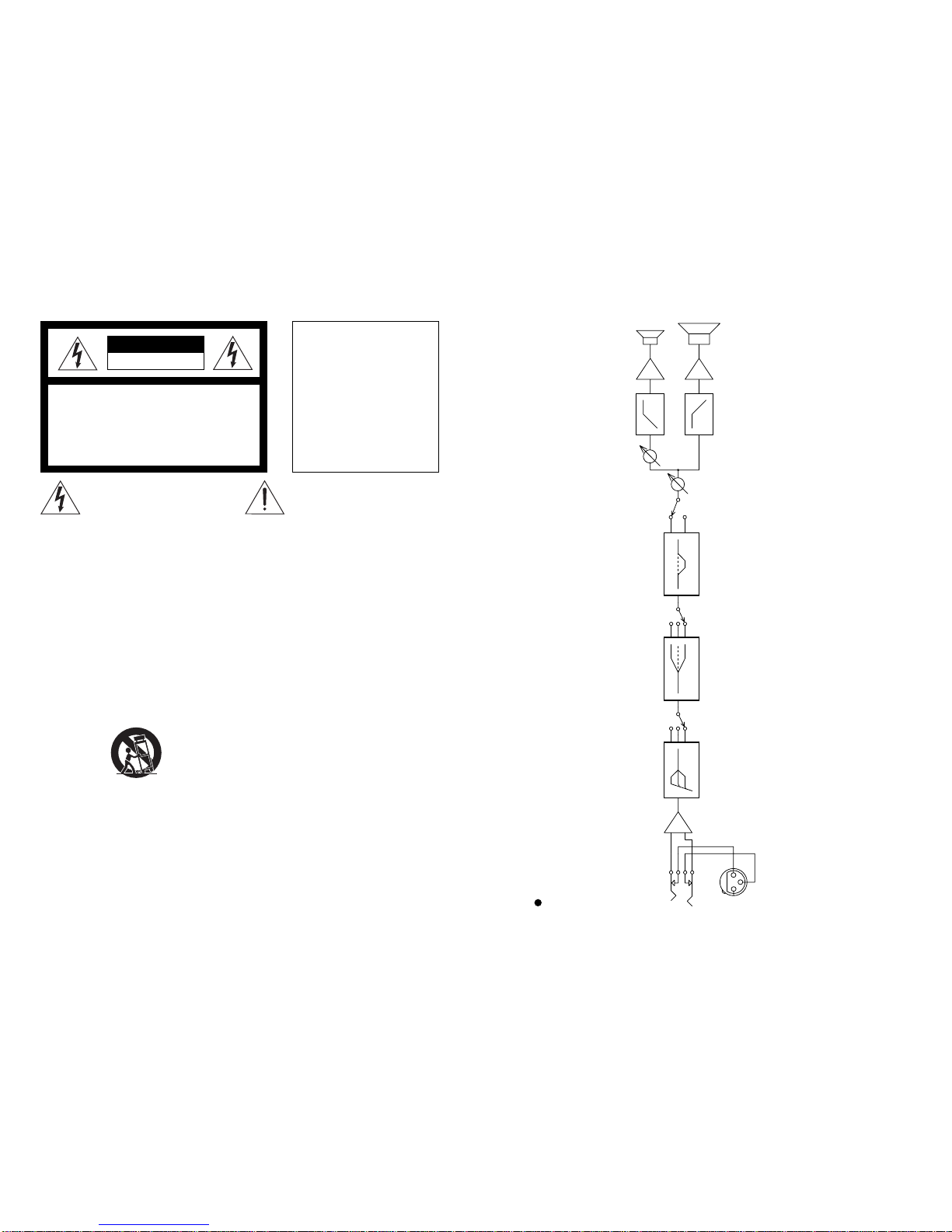
NF-1A Block Diagram
INPUT (UNBAL)
-10dBV
INPUT (BAL)
+4dBu
1: GND
2: HOT
3: COLD
+3dB
LO FREQ.
60Hz
-3dB
HIGH FREQ.
10kHz
+3dB
-3dB3kHz
OFF
HI-MID ATT. VOL
HF POWER TWEETER
WOOFERLF POWER
TWEETER
LEVEL
-3dB 0dB 0dB ON
19
NF-1 & NF-1A NF-1 & NF-1A
Input PCB
3
2
8
4
1
57
6
57
6
57
6
3
2
8
4
1
17
19 1618 20
S110D
7
9
6 8
10
2
413
21
22
5
17
19 1618 20
2
4
1 3
21
22
5
1
32
7
8
3
2
84
1
3
2
1
5
4
3
2
1
5
4
J101
INPUT (UNBAL)
INPUT (BAL)
-10dBV
+4dBu
J102
1
4
C50
JUMPER
3
R106
10K
2
8
7
3
2
4
5
1
R108
8.2K
C102
10/16
C101
10/16
L102
BEAD R102
20K
R101
20K
R103
20K
L101
BEAD
R107
10K
R104
20K
+15V C105
1/50
C106
1/50
-15V
C51
NON
U101A
BA4560N
C104
47p CER
C103
47p CER
C107
10/16
R105
47K
C111
0.027PES C117
0.027PES
R110
39K R111
82K
S110B
R113
1M R114
43K
R112
430K
U101B
BA4560N
C120
10/16
R115
47K
C131
10/16
R131
10K
R132
10K
C134
0.0022
PES
R136
20K
R133
6.8K
C113
1/50 -15V
+15V
R134
18K
R135
4.7K
U102A
BA4560N
C112
1/50
S130A
R121
47K
C122
0.015 PES
R122
3K
C118
10/16
R123
3K
C123
0.015 PES
C124
0.015 PES
U102B
BA4560N
R124
1.6K
R127
470
R125
1K
C125
NON
R126
4.7K
C126
10/16
R128
47K
S120A
VOL.
R140
10KA
C121
10/16
U103B
BA4560N
R139
47K
R129
4.7K R120
4.7K
-15V
1
2
J103
TO POWER LED
J104
TO POWER AMP
1
2
3
4
5
+15V
R117
2K
C119
NON
C132
1/50
+15V
U103A
BA4560N
R141
10KB
C115
10/16 C133
1/50
R116
47K
-15V
R118
3K
C114
1/50
R119
1.6K
TWEETER
LEV.
HI-MID ATT.
OFF
ON
HI-FREQ.
+3dB
0dB
-3dB
LO FREQ.
+3dB
0dB
-3dB
C136
10/16
S130D
R137
20K
C135
NON
S110A
TABLE OF CONTENTS
NF-1 owner's manual : 8288457000 (for export & domestic model)
NF-1A owner’s manual : 8288459000 (for export model)
: 8288460000 (for domestic model)
Parts List, exploded views and circuit diagrams are given in this manual to assist the service
technician in maintaining the Model NF-1 & NF-1A.
NOTES
The following accessories are supplied with NF-1 as the standard accessories.
*
*
Following is the packing material for the Model NF-1.
*
Carton, inner, 3 pads, NF-1 : 8228739000
Carton, outer, NF-1 : 8228917000
Sheet, mirror : 8216729000
1. SPECIFICATIONS . . . . . . . . . . . . . . . . . . . . . . . . . . . . . . . . . . . . .
2. CONTROLS, INDICATORS & CONNECTORS . . . . . . . . . . . . . .
3. EXPLODED VIEW, PCB ASSEMBLY & PARTS LIST . . . . . . . .
4. CIRCUIT & BLOCK DIAGRAMS . . . . . . . . . . . . . . . . . . . . . . . .
4
6
7
17
Following is the packing material for the Model NF-1A.
*
Carton, inner, NF-1A : 8228738000
Carton, outer, NF-1A : 8228916000
Packing, side, NF-1A : 8228466001
Packing, front, NF-1A : 8228466002
Sheet, mirror : 8216729000
18 3

NF-1 & NF-1A NF-1 & NF-1A
417
1. SPECIFICATIONS
Enclosure system 2-way bass-reflex system
Drivers 160 mm HP woofer x 1 (low-leakage type)
20 mm Soft-Dome tweeter x 1 (low-leakage type)
Impedance 8 Ω
Frequency Response 50 Hz ~ 40 kHz
Crossover Frequency 10 kHz
Sound Pressure Level 89 dB/W (1 m)
Input (Program) 120 W
Enclosure volume 11 liters
Weight Approx. 9.1 kg
NF-1
Specifications and physical appearance are subject to change without notice for product improvement.
4000020000100005000200010005002001005020
80
90
70
60
50
40
30
20
100
10 Hz
dB
10
Second Distortion
Third Distortion
<NF-1 Distortion Characteristic>
30º
60º
4000020000100005000200010005002001005020
90
100
80
70
60
50
40
30
110
10 Hz
dB
8
16
32
4
<NF-1 Frequency / Impedance Characteristic>
Ω
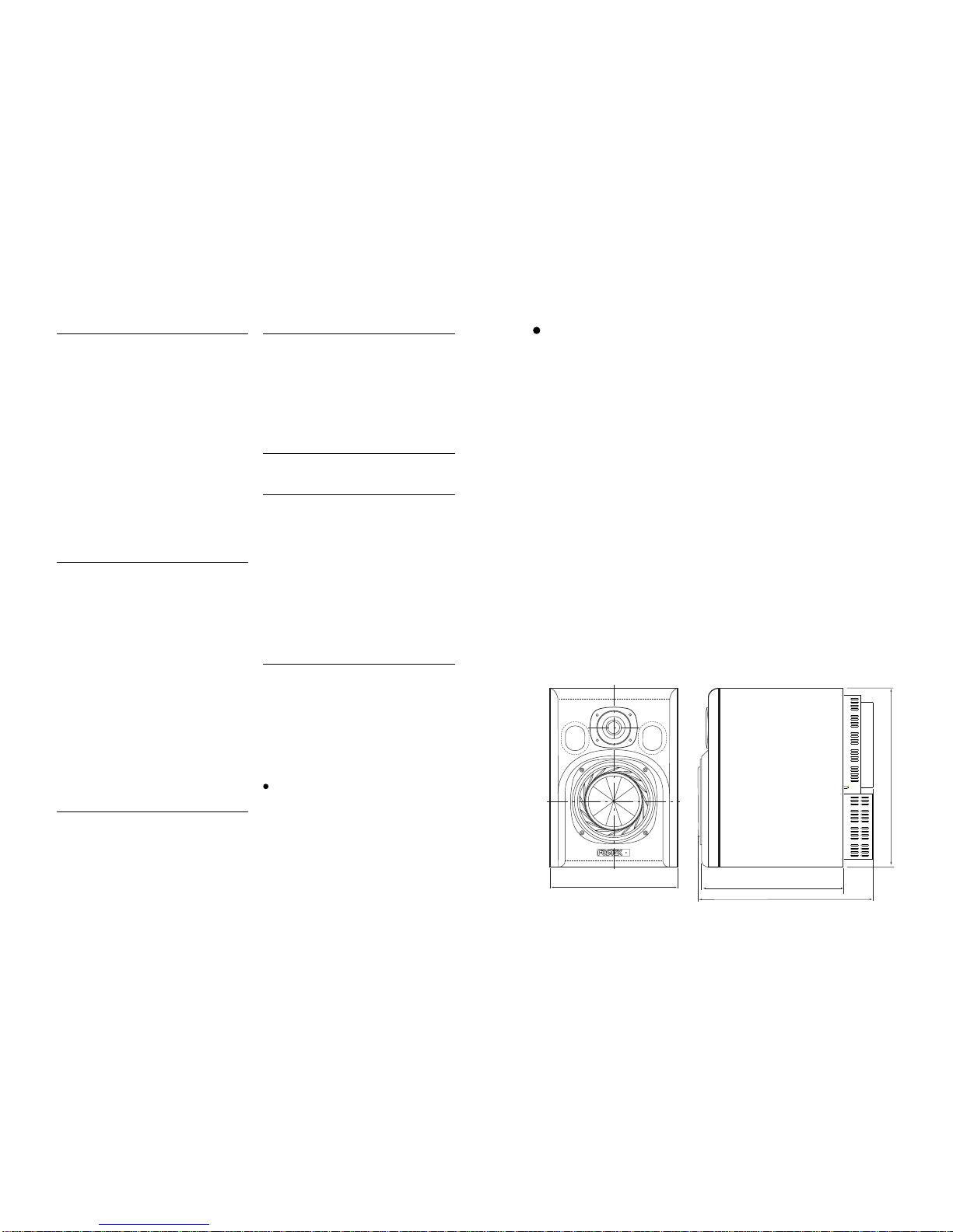
274 mm
267 mm
340 mm
240 mm
• NF-1 Dimensions
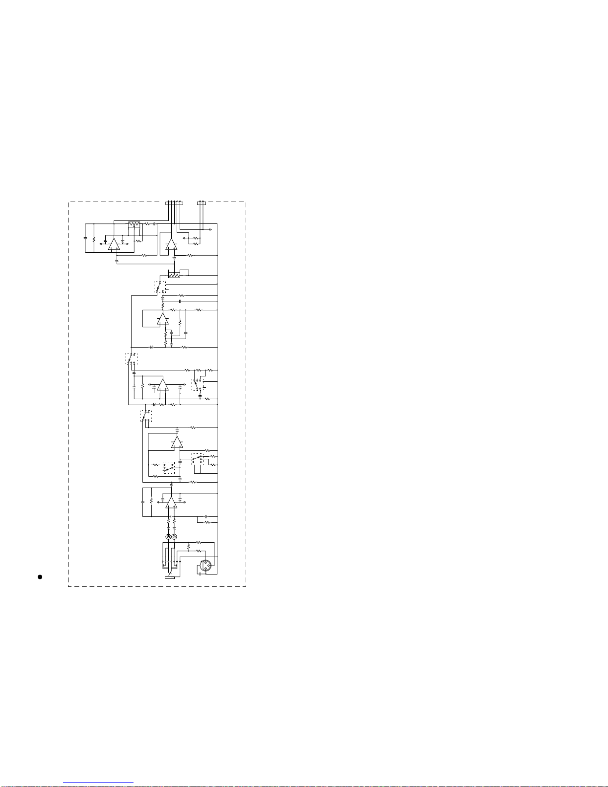
4. CIRCUIT & BLOCK DIAGRAMS
Power Amp & SW PCB
1
2
45
6
7
8
9
10
11
1
1
1
3
2
84
1
57
6
3
1
2
1
1
F1
FUSE
C506 47p CER
R507 10K
U502
LM3886TF
IN+ OUT3
+V
IN-
+38V
+V
NC
GND
MUTE -V
R506
150
C505
1/50
C509
0.1 PES
R509
10
NC
NC
R505
1K
C508
220p CER
-38V
R508
20K
TO LF
SPEAKER
J502
TO HF
SPEAKER
1
2
3
4
R515
10K
C513
47p CER
1
2
45
6
7
8
9
10
11
U510
LM3886TF
IN+ OUT3
+V
IN-
+38V
+V
NC
GND
MUTE -V
NC
NC
-38V
C517
0.1 PES
R516
20K
C516
220p CER
U501B
BA4560N
C511
0.0022 PES
R512
1K
C512
100/16
R510
10K R511
10K
C510
0.0039PES
R504
20K
R503
10K
C503
0.01 CER
U501A
BA4560N
C504
0.01CER
C502
0.0022PES
+15V
-15V
C501
0.0022PES
+15V
-15V
1
2
3
4
5
W501
TO INPUT
R517
10
R513
130
+15V
-38V
C008
100/16
R004
270 1/2W RF
+38V
U001
DTC114ES R003
470K
Q001
2SD1200F
C002
4700/63 D002
MTZJ15
C006
10/16
C004
1/50
R001
4.7K
C007
10/16
D003
MTZJ15
Q002
2SB889F -15V
R002
4.7K
C005
1/50
C003
4700/63
-38V R005
270 1/2W RF
C013
NON
D001
GBU6D
CONN-M-03 C014
NON
J501
1
2
3
1
2
3
T1
TRANSFORMER POWER
W6
100V: GRY
120V: BRN
230V: VIO
S1
SW POWER
W3
W5
W4
C011
0.0047
C012
NON
L1
BEAD 6H
L2
BEAD 6H
J001
AC IN 230V: 1A
100/12V: 3.15A
W1
BRN
BRN
WHT
GND
NF-1 & NF-1A NF-1 & NF-1A
16 5
Ref. No. Part No. Description
8274 2720 00 PCB Assy, SW, NF-1A
8251 9930 03 Plain PCB, SW, NF-1A
Ref. No. Part No. Description
C011 8256 0750 05 Spark killer, 0.0047µF
C012 N/A
E001 8239 0002 00 Holder, PI, fuse, S-N5057
J001 8245 3210 00 Connector, PL, jack, AC-INLET, 3P,
0714-FR7
L001, 002 8242 1340 01 Filter, EMI, 6 hole
S001 8253 4710 03 SW, PI, rocker, power, EST15
W001 8277 1630 15 Cable assy, earth lug, SIN1.8, L150
W003, 004 8245 5430 00 Terminal, IPS-5007
W005, 006 8277 1610 10 Cable assy, SIN1.8 - wire, L100
• SW PCB assy
Ref. No. Part No. Description
R121 8230 1384 73 HT, Carbon, 1/4W, 47kΩ, 5%
R122, 123 8230 1383 02 HT, Carbon, 1/4W, 3kΩ, 5%
R124 8230 1381 62 HT, Carbon, 1/4W, 1.6kΩ, 5%
R125 8230 1381 02 HT, Carbon, 1/4W, 1kΩ, 5%
R126 8230 1384 72 HT, Carbon, 1/4W, 4.7kΩ, 5%
R127 8230 1384 71 HT, Carbon, 1/4W, 470Ω, 5%
R128 8230 1384 73 HT, Carbon, 1/4W, 47kΩ, 5%
R129 8230 1384 72 HT, Carbon, 1/4W, 4.7kΩ, 5%
R131, 132 8230 1381 03 HT, Carbon, 1/4W, 10kΩ, 5%
R133 8230 1386 82 HT, Carbon, 1/4W, 6.8kΩ, 5%
R134 8230 1381 83 HT, Carbon, 1/4W, 18kΩ, 5%
R135 8230 1384 72 HT, Carbon, 1/4W, 4.7kΩ, 5%
R136, 137 8230 1382 03 HT, Carbon, 1/4W, 20kΩ, 5%
R139 8230 1384 73 HT, Carbon, 1/4W, 47kΩ, 5%
R140 8240 2930 06 Pot., PI, RT9, 10kΩA, EVUE2A
R141 8240 2930 07 Pot., PI, RT9, 10kΩB, EVUE3A
CAPACITORs
ALU = Electrolytic type
CER = Ceramic type
PES = Mylar type
Ref. No. Part No. Description
C050, 051 N/A
C101, 102 8232 1431 06 VT, ALU, 16V, 10µF, 20 %, SME-VB
C103, 104 8232 8014 70 VT, CER, 50V, 47pF, 5%, SL
C105, 106 8232 1461 05 VT, ALU, 50V, 1µF, 20 %, SME-VB
C107 8232 1431 06 VT, ALU, 16V, 10µF, 20 %, SME-VB
C111 8232 9012 73 VT,PES, 50V, 0.027µF, 5%, AMZF
C112~114 8232 1461 05 VT, ALU, 50V, 1µF, 20 %, SME-VB
C115 8232 1431 06 VT, ALU, 16V, 10µF, 20 %, SME-VB
C116 N/A
C117 8232 9012 73 VT,PES, 50V, 0.027µF, 5%, AMZF
C118 8232 1431 06 VT, ALU, 16V, 10µF, 20 %, SME-VB
C119 N/A
C120, 121 8232 1431 06 VT, ALU, 16V, 10µF, 20 %, SME-VB
C122~124 8232 9011 53 VT, PES, 50V, 0.0015µF, 5%, AMZ
C125 N/A
C126 8232 1431 06 VT, ALU, 16V, 10µF, 20 %, SME-VB
C131 8232 1431 06 VT, ALU, 16V, 10µF, 20 %, SME-VB
C132, 133 8232 1461 05 VT, ALU, 50V, 1µF, 20 %, SME-VB
C134 8232 9012 22 VT,PES, 50V, 0.0022µF, 5%, AMZF
C135 N/A
C136 8232 1431 06 VT, ALU, 16V, 10µF, 20 %, SME-VB
MISCELLANEOUS
Ref. No. Part No. Description
E001 Wire, jumper, F5
E002 Wire, jumper, F10
J101 8245 3390 09 Connector, PI, jack, phone,
YKB21-5006
J102 8245 2680 03 Connector, PI, jack, XLR, NC3FAH2-0
J103 8245 0530 02 Connector, PI, jack, 8283, 2P, WHT
J104 8245 3080 05 Connector, PI, jack, 5P, SBRK 5S-4
L101, 102 8242 1860 13 Filter, T, EMI, LEF7B-M3R2T
DIP: Dual In Line
H: Horizontal mount
ZIP: Zigzag in-line package
SIP: Single in-line package
V: Vertical mount
T: Taping device
P: Penetrate mount
I: I form (straight)
L: L form (right angle)
DG: Digital
AN: Analogue
Abbreviation
Ref. No. Part No. Description
S110 8253 6550 19 SW, PL, slide, 4-3, non-shortening,
SSSFI, L06
S120 8253 6550 20 SW, PL, slide, 2-2, non-shortening,
SSSFI, L06
S130 8253 6550 19 SW, PL, slide, 4-3, non-shortening,
SSSFI, L06
Ref. No. Part No. Description
D001 8234 1044 00 Opt., LED, GRN, SLR-342MG3F
W001 8276 3340 20 Cable assy, 2P,
WHT8263/F-8263/F, L200
Y101 8207 0051 08 Spacer, LED, 11, LH-5-11
• LED assy
NF-1A
Specifications and physical appearance are subject to change without notice for product improvement.
Speakers
Enclosure system 2-way bass-reflex system
Drivers 160 mm HP woofer x 1 (low-leakage type)
20 mm Soft-Dome tweeter x 1 (low-leakage type)
Impedance 8 Ω
Reproduction Frequency Response 50 Hz ~ 40 kHz
Enclosure volume 9.2 liters
Maximum output sound level 106 dB (with VOL max./rated input)
Amplifiers
Output power 60 W each for low and high frequency amplifiers
Tweeter SPL adjustable level ± 3 dB
Filter characteristic adjustable level
HI-FREQ (10 kHz) + 3 / 0 / - 3 dB (selective)
LO-FREQ (60 Hz) + 3 / 0 / - 3 dB (selective)
HI-MID ATT. (3 kHz) 0 dB when switched off.
- 3 dB when switched on.
Input terminals XLR-3-31 type (for balanced input)
∅6 mm phone jack (for unbalanced input)
Normal input level +4 dBu (XLR balanced input)
-10 dBV (phone unbalanced input)
Input impedance 20 kΩor more
Crossover frequency 5 kHz
OthersWeight Approx. 11 kg
Power supply 120 V AC, 60 Hz
230 V AC, 50 Hz
Power consumption 52 W
320 mm
267 mm
340 mm
240 mm
• NF-1A Dimensions

NF-1 & NF-1A NF-1 & NF-1A
615
2. CONTROLS, INDICATORS & CONNECTORS
1. Power LED
2. Heat sink
3. Loudness control [VOL, -∞~ MAX (0dB)]
4. Tweeter level control
[TWEETER LEVEL, -3 ~ 0dB ~ +3]
5. Hi-Mid attenuator [HI-MID ATT., ON / OFF]
6. High-frequency filter selector
[HI-FREQ, +3dB / 0 / -3]
7. Low-frequency filter selector
[LO-FREQ, +3dB / 0 / -3]
8. Unbalanced input terminal
[INPUT, UNBAL -10dBV (phone jack)]
9. Balanced input terminal
[INPUT, BAL +4dBu (XLR)]
10. Power switch [POWER]
11. AC IN connector [AC IN]
NF-1A
AC IN
3k1k 5kHz10kHz
-3dB
0dB
-3dB
0dB
+3dB
HI-MID ATT.HI FREQLO FREQ
-3dB
0dB
+3dB
60Hz
RISQUE ELECTRIQUECHOCDE
CAUTION
RISK OF ELECTRIC SHOCK
DO NOT OPEN
AVIS:
NE PAS OUVRIR.
WARNING:
TO
SHOCK,DO NOT EXPOSE THIS EQUIPMENT
TO RAIN OR MOISTURE.
REDUCETHE RISKOF FIREOR ELECTRIC
OFF
ON
POWER
+4dBu
BAL
3:C
2:H
1:G
-10dBV
UNBAL
INPUT
-3
0
+3dB
LO FREQ
-3
0
+3dB
HI FREQ
OFF
ON
HI-MID ATT.
MAX
(0dB)
VOL
LEVEL
TWEETER
0dB
-3
+3
3
4
5
6
7
8
9
10
11
2
1
Ref. No. Part No. Description
8274 2700 00 PCB Assy, Power Amp, NF-1A
8251 9930 01 Plain PCB, Power Amp, NF-1A
ICs
Ref. No. Part No. Description
U001 8236 0781 01 PT, DG, driver, DTC114ES
U501 8236 0361 00 PT, SIP, AN, op amp, BA4560N
U502 8236 0466 00 HZIP, AN, power amp, LM3886TF
U510 8236 0466 00 HZIP, AN, power amp, LM3886TF
TRANSISTORs
Ref. No. Part No. Description
Q001 8234 1099 00 V, NPN, 2SD1200F
Q002 8234 1100 00 V, PNP, 2SB889F
DIODEs
Ref. No. Part No. Description
D001 8234 1977 01 V, stack, GBU6D
D002, 003 8234 5039 59 HT, zener, 15V, MTZJ15
RESISTORs
Ref. No. Part No. Description
R001, 002 8230 1384 72 HT, Carbon, 1/4W, 4.7kΩ, 5%
R003 8230 1384 74 HT, Carbon, 1/4W, 470kΩ, 5%
R004, 005 8230 1292 71 H, fuse, 1/2W, 270Ω, 5%
R501, 502 N/A
R503 8230 1381 03 HT, Carbon, 1/4W, 10kΩ, 5%
R504 8230 1382 03 HT, Carbon, 1/4W, 20kΩ, 5%
R505 8230 1381 02 HT, Carbon, 1/4W, 1kΩ, 5%
R506 8230 1381 51 HT, Carbon, 1/4W, 150Ω, 5%
R507 8230 1381 03 HT, Carbon, 1/4W, 10kΩ, 5%
R508 8230 1382 03 HT, Carbon, 1/4W, 20kΩ, 5%
R509 8230 1381 00 HT, Carbon, 1/4W, 10Ω, 5%
R510, 511 8230 1381 03 HT, Carbon, 1/4W, 10kΩ, 5%
R512 8230 1381 02 HT, Carbon, 1/4W, 1kΩ, 5%
R513 8230 1381 31 HT, Carbon, 1/4W, 130Ω, 5%
R514 8230 1384 72 HT, Carbon, 1/4W, 4.7kΩ, 5%
R515 8230 1381 03 HT, Carbon, 1/4W, 10kΩ, 5%
R516 8230 1382 03 HT, Carbon, 1/4W, 20kΩ, 5%
R517 8230 1381 00 HT, Carbon, 1/4W, 10Ω, 5%
CAPACITORs
ALU = Electrolytic type
CER = Ceramic type
PES = Mylar type
Ref. No. Part No. Description
C002, 003 8232 2054 78 VT, ALU, 63V, 4700µF, 20%,
SMH-VNSN
C004, 005 8232 1461 05 VT, ALU, 50V, 1µF, 20 %, SME-VB
C006, 007 8232 1431 06 VT, ALU, 16V, 10µF, 20 %, SME-VB
C008 8232 1431 07 VT, ALU, 16V, 100µF, 20 %, SME-VB
C013, 014 N/A
C501, 502 8232 9012 22 VT, PES, 50V, 0.0022µF, 5%, AMZF
• POWER AMP PCB assy
Ref. No. Part No. Description
C503, 504 8232 8031 03 VT, CER, 50V, 0.01µF, 5%, YF
C505 8232 1461 05 VT, ALU, 50V, 1µF, 20 %, SME-VB
C506 8232 8014 70 VT, CER, 50V, 47pF, 5%, SL
C507 N/A
C508 8232 8012 21 VT, CER, 50V, 220pF, 5%, SL
C509 8232 9011 04 VT, PES, 50V, 0.1µF, 5%, AMZ
C510 8232 9013 92 VT, PES, 50V, 0.0039µF, 5%, AMZF
C511 8232 9012 22 VT, PES, 50V, 0.0022µF, 5%, AMZF
C512 8232 1431 07 VT, ALU, 16V, 100µF, 20 %, SME-VB
C513 8232 8014 70 VT, CER, 50V, 47pF, 5%, SL
C514, 515 N/A
C516 8232 8012 21 VT, CER, 50V, 220pF, 5%, SL
C517 8232 9011 04 VT, PES, 50V, 0.1µF, 5%, AMZ
MISCELLANEOUS
Ref. No. Part No. Description
E001 Wire, jumper, F5
E002 Wire, jumper, F10
E003 8207 0122 05 Holder, cable, 5P, 51048 (W501)
J501 8245 3050 03 Connector, PI, jack, VH, 3P, WHT
J502 8245 3050 04 Connector, PI, jack, VH, 4P, WHT
Y401 8221 3301 00 Bracket, pcb, power amp, NF-1A
W005~007 8245 5430 00 Terminal, IPS-5007
W501 8276 9185 15 Cable, flat, 5P, S-KINK, L150
W502 N/A
• INPUT PCB assy
Ref. No. Part No. Description
8274 2710 00 PCB Assy, Input, NF-1A
8251 9930 02 Plain PCB, Input, NF-1A
ICs
Ref. No. Part No. Description
U101~103 8236 0361 00 SIP, AN, op amp, BA4560N
RESISTORs
Ref. No. Part No. Description
R101, 102 8230 1382 03 HT, Carbon, 1/4W, 20kΩ, 5%
R103, 104 8230 1382 03 HT, Carbon, 1/4W, 20kΩ, 5%
R105 8230 1384 73 HT, Carbon, 1/4W, 47kΩ, 5%
R106, 107 8230 1381 03 HT, Carbon, 1/4W, 10kΩ, 5%
R108 8230 1388 22 HT, Carbon, 1/4W, 8.2kΩ, 5%
R110 8230 1383 93 HT, Carbon, 1/4W, 39kΩ, 5%
R111 8230 1388 23 HT, Carbon, 1/4W, 82kΩ, 5%
R112 8230 1384 34 HT, Carbon, 1/4W, 430kΩ, 5%
R113 8230 1381 05 HT, Carbon, 1/4W, 1MΩ, 5%
R114 8230 1384 33 HT, Carbon, 1/4W, 43kΩ, 5%
R115, 116 8230 1384 73 HT, Carbon, 1/4W, 47kΩ, 5%
R117 8230 1382 02 HT, Carbon, 1/4W, 2kΩ, 5%
R118 8230 1383 02 HT, Carbon, 1/4W, 3kΩ, 5%
R119 8230 1381 62 HT, Carbon, 1/4W, 1.6kΩ, 5%
R120 8230 1384 72 HT, Carbon, 1/4W, 4.7kΩ, 5%
NF-1A PCB Assy Parts List

NF-1 & NF-1A NF-1 & NF-1A
14 7
SW
8251993 003
C011
C012
J001
L
N
W6
W3
PT
W1
GND
W4
PT (WHT)
EUR/UK
JPN/USA/CND
T1A 250V
3.15A 125V
L2
L1
W5 SW
F1
• Parts side of SW PCB assy
C011
C012
J001
LN
W6
W3 PT
W3 PT (WHT)
L2
L1
W5
SW
F1
• Foil side of SW PCB assy
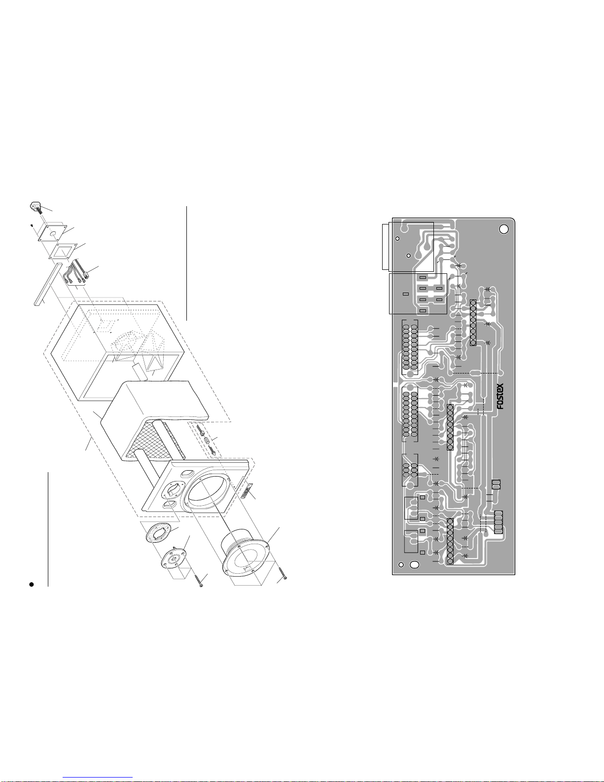
3. EXPLODED VIEW, PCB ASSEMBLY AND PARTS LIST
Ref. No. Part No. Description
1 B805 5830 00 Woofer, NF-1/NF-1A
2 B805 5829 00 Tweeter, NF-1/NF-1A
3 8216 7300 00 Packing
4 8260 5760 00 Enclosure assy, NF-1
5 8216 7280 00 Damping material, 490 x 190 x 10
6 8214 3940 00 Bolt, M3, torx button, L20, T
(included in the enclosure assy)
7 8214 3930 00 Bolt, M4, torx button, L20, T
(included in the enclosure assy)
8 8216 7240 00 HP reflector, NF-1 (not included
in the enclosure assy)
9 8245 3580 00 Terminal, CL-S48-1
10 8276 9200 00 Cord, red, L = 350
11 8276 9200 01 Cord, blk, L = 350
NF-1 OVERALL EXPLODED VIEW & PARTS LIST
Ref. No. Part No. Description
12 8276 9200 03 Cord, blk, L = 300
13 8277 5020 00 Cable assy, L = 300 (+ C 1.0µF)
14 0532 1031 06 CM1.0, film capacitor
15 8220 8490 00 Emblem, FOSTEX
RED (+): To Woofer
BLK (-): To Woofer
1
2
4
9
5
8
3
6
7
7
7
10
11
12
13
15 14
8
RED (+): To Tweeter
BLK (-): To Tweeter
NF-1 & NF-1A NF-1 & NF-1A
813
Ref. No. Part No. Description
1 B805 5830 00 Woofer, NF-1
2 B805 5829 00 Tweeter, NF-1
3 8216 7300 00 Packing
4 8260 5770 00 Enclosure assy, NF-1A
5 8216 7280 00 Damping material, 490 x 190 x 10
6 8214 3940 00 Bolt, M3, torx button, L20, T
(included in the enclosure assy)
7 8214 3930 00 Bolt, M4, torx button, L20, T
(included in the enclosure assy)
Ref. No. Part No. Description
8 8216 7240 00 HP reflector, NF-1 (not included
in the enclosure assy)
9 8270 8830 00 LED assy, NF-1A
10 8277 5041 45 Cable assy, 2P,
WHT8263/F-8263/M, L450
11 8277 5010 00 Cable assy, SP, NF-1A
12 8216 7340 02 Sheet, connector, NF-1A
13 8221 3290 00 Bracket, connector, NF-1A
14 8207 0002 25 Bushing, SR-6N3-4
15 8216 7350 00 Sheet, chassis, NF-1A
16 8218 7950 00 Plate, name, NF-1A
NF-1A OVERALL EXPLODED VIEW (Speaker & Enclosure Section)
1
2
45
8
3
6
7
POWER
8
9
10
11
12
13
14
BTP3 x 16BZn
15
16
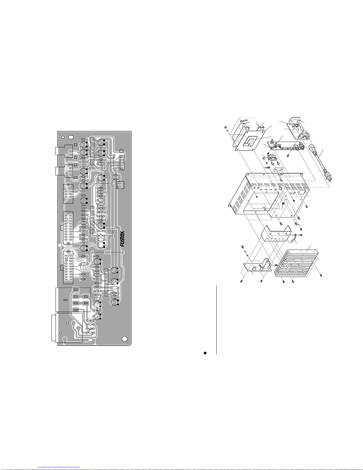
• Foil side of Input PCB assy
INPUT. NF-1A
R139
R116
R119
R118
R128
R125
R127
R132
R136
C134
R133
R134
R135
C111
R113
R114
R105
C121
C115
C114
C118
C126
C131
C133
C112
C113
C136
C120
C105
C106
C107 C102
C101
L102
L101
C119
R124
C124
C123
C122
C135
C117
C51
R117
R126
R120
R129
R121
R122
R125
R123
R131
R115
R111
R112
R101
R102
R104
C104 R103
R106
R108
R107
C050
C103
R110
R137
C132
U103 U102
U101
R140 R141 S120 S130 S110
J101
32
8745
1
H
C
G
S
J102
J104
1J103
12
5
NF-1 & NF-1A NF-1 & NF-1A
12 9
8251993 002
INPUT
R139
R116
R119
R118
R128
R125
R127
R132
R136
C134
R133
R134
R135
C111
R113
R114
R105
C121C115
C114C118
C126
C131
C133
C113
C136
C120
C105
C106
C107
C102
C101
L102
L101
C119
R124
J103
21
C124
C123
C122
C135
C117
C51
R117
R126
C112
R129
R120
R121
R122
R125
R123
R131
R115
R111
R112
R101
R102
R104
C104
R103
R106
R108
R107
C050
C103
R110
R137
C132
U101
U102 U103
S120 TW LEV
R141 VOL
R140
HI-MID ATT
S130S110 HI CARCTLO CARCT
J101
J102
J104
1
• Parts side of Input PCB assy
NF-1A OVERALL EXPLODED VIEW (Amplifier Section)
Ref. No. Part No. Description
17 8221 3311 00 Chassis, amp, NF-1A
18 8221 2610 00 Bracket, AC-IN, FD-8/NF-1A
19 8216 7370 00 Cover, SW, NF-1A
20 8207 0133 10 Heat sink, NF-1A
21 8274 2700 00 PCB assy, Power Amp, NF-1A
22 8274 2710 00 PCB assy, Input, NF-1A
23 8274 2720 00 PCB assy, SW, NF-1A
24 8204 0580 04 Spacer, 6, M3 x 6
25 8242 2680 00 Transformer, power, 120V,
USA/CND, NF-1A
8242 2690 00 Transformer, power, 230V,
EUR/UK, NF-1A
8242 2700 00 Transformer, power, 100V,
JPN, NF-1A
26 8253 4230 00 SW, WI, rocker, power,
SDDLA1
27 8216 7340 01 Sheet, transformer, NF-1A
28 8245 3400 00 Nut, phone jack
29 8221 3360 00 Bracket, PCB, input, NF-1A
30 8239 1003 19 Fuse, 20, TLAG, 3.15A, 125V,
USA/CND/JPN
8239 0007 10 Fuse, 20, TDLY, 1A, 250V,
EUR/UK
31 8276 8010 00 Code, power, UL/CSA,
VM0033-0089, USA/CND
8276 8021 00 Cord, power, CEE,
0309B-0310B, EUR
8276 9170 00 Cord, power, BS, 3C,
KP610-KS31A, UK
8276 8000 00 Cord, power, DM,
VM1292-1298, JPN
32 8216 7340 03 Sheet, transformer, B
33 8207 0117 04 Holder, cord, CS-1
BBT3 x 8
BZn
BBT3 x 8BZn
17
18
19
20
21
22
BBT3 x 8BZn
BBT3 x 8BZn BTP3.5 x 8BZn
BBT3 x 8
BZn
23
24
25
27
N4
26
BTT4 x 10
BZn
BTT4 x 10
BZn
LW4
N4
LWE4
BBT3 x 8
BZn
BTP3.5 x 8BZn
BBT3 x 8
BZn
28
29
BTT4 x 10
BZn
B3 x 8BZn
B3 x 4BZn
BBT3 x 8
BZn
LWE3
30
31
32
LW3.5
W3.5
BTT4 x 10
BZn
33
From
Transformer
GND cable
BBT3 x 6BZn

NF-1 & NF-1A NF-1 & NF-1A
10 11
• Foil side of Power Amp PCB assy
U502 U510
C509
C505
C007
C504
C503
C006
D003
D002 C005
C002 C003
C004
R504
R503
C501
C502
C511
R511
R510
C510
R512
R513
C517
J502
14
J501
D001
1
1
3
R516
C508
R506
R509 R508 C513
R515
R517
C014
C013
AC
AC
R005
R004
R003 C008 C512
C506
R507
R505
R516
R001
Q001
R002
Q002
U501
U001
W501
1
13
15
11 111 1
NF-1A PCB Pattern Drawing
• Parts side of Power Amp PCB assy
D001
J501
P.TRANS
C013 C003 R517
U510
113
B
B
E
E
11
U502
111
LF (HOT)
HF (HOT)
C517
R513
D003
C503
C504
R503
C510
R510
R511
C511
C504
C502
D002 C516
R512
J502 SPEAKER
14
R515
R003
R508
R505
R506
C508
C509
R507
C506
R509
R516
C512 C008
R002
R001
R005
R004
POWER AMP
8251993 001
Q002
Q001
C005
C004 C006 C007
C505
U501 W501
TO INPUT
1
15
U001
C513
C002
C014
1
31
Other manuals for NF-1
3
This manual suits for next models
1
Table of contents
Other Fostex Speakers System manuals

Fostex
Fostex PM0.5d User manual

Fostex
Fostex SN0.1 User manual

Fostex
Fostex NF-1 User manual

Fostex
Fostex SPA11 User manual

Fostex
Fostex RM-3 User manual

Fostex
Fostex RM-2 User manual

Fostex
Fostex SPA12 User manual

Fostex
Fostex PM0.3 User manual

Fostex
Fostex RM-3DT User manual

Fostex
Fostex 6301BX User manual


