FOTILE GLG30301 User manual

INSTALLATION
MANUAL
Gas Cooktop
Read all instructions before
using this appliance
GLG30301 GLG30401-Y GLG30401
1102002508070
Tous les efforts ont été faits pour sʼassurer que les informations fournies dans ce manuel
sont correctes au moment de lʼimpression. Cependant, en raison de lʼamélioration continue
des produits, FOTILE se réserve le droit de modifier les produits et les données techniques
sans préavis.
Société à responsabilité des ustensiles de cuisine de Ningbo FOTILE
N°218, Rue N°2 de Binhai, Nouvelle zone de Hangzhouwan, Ville de Cixi, Province du Zhejiang, Chine
WWW.FOTI LEGLOBAL.COM

-2--1-
Contents
Important Safety Information
Packing List And Tools
Before You Begin
Product Dimensions
Clearance Dimensions
Installation Requirements
Installation Instructions
Installing The Cooktop
Connecting The Cooktop To Gas Supply
Electrical Connections
Burner Components And Grate Installation
Check The Ignition And Flame Quality
LP Conversion Instructions
2
6
7
7
9
8
11
12
13
16
13
18
11
Read all instructions before using this appliance
Save this manual. Please do not discard.
We have provided many important safety messages in this manual and on your appliance.
Always read and obey all safety messages.
All safety messages will tell you what the potential hazard is, tell you how to reduce the chance
of injury, and tell you what can happen if the instructions are not followed.
You can be killed or seriously injured if you do not immediately follow
instructions.
You can be killed or seriously injured if you do not follow instructions.
This is the safety alerts symbol.
This symbol alerts you to potential hazards that can kill or hurt you and others.
All safety messages will follow the safety alerts symbol and either the word
“DANGER” or “WARNING.”
These words mean:
Your safety and the safety of others are very important
DANGER
WARNING
WARNING
0M[OLPUMVYTH[PVUPU[OPZTHU\HSPZUV[MVSSV^LKL_HJ[S`HMPYLVYL_WSVZPVUTH`YLZ\S[
JH\ZPUNWYVWLY[`KHTHNLWLYZVUHSPUQ\Y`VYKLH[O
¶+VUV[Z[VYLVY\ZLNHZVSPULVYV[OLYMSHTTHISL]HWVYZHUKSPX\PKZPU[OL]PJPUP[`VM[OPZVY
HU`V[OLYHWWSPHUJL
¶>/(;;6+60-@6<:4,33.(:!
+VUV[[Y`[VSPNO[HU`HWWSPHUJL
+VUV[[V\JOHU`LSLJ[YPJHSZ^P[JO
+VUV[\ZLHU`WOVULPU`V\YI\PSKPUN
0TTLKPH[LS`JHSS`V\YNHZZ\WWSPLYMYVTHULPNOIVYZWOVUL-VSSV^[OLNHZZ\WWSPLYZ
PUZ[Y\J[PVUZ
0M`V\JHUUV[YLHJO`V\YNHZZ\WWSPLYJHSS[OLMPYLKLWHY[TLU[
¶0UZ[HSSH[PVUHUKZLY]PJLT\Z[ILWLYMVYTLKI`HX\HSPMPLKPUZ[HSSLYZLY]PJLHNLUJ`VY[OL
NHZZ\WWSPLY
Important safety information

-4--3-
WARNING
INSTALLATION PRECAUTIONS
WARNING
Gas leaks cannot always be detected by smell.
Gas suppliers recommend that you use a gas detector approved by UL or CSA.
For more information, contact your gas supplier.
WARNING
5L]LYVWLYH[L[OL[VWZ\YMHJLJVVRPUNZLJ[PVUVM[OPZHWWSPHUJL\UH[[LUKLK
-HPS\YL[VMVSSV^[OPZ^HYUPUNZ[H[LTLU[JV\SKYLZ\S[PUMPYLL_WSVZPVUVYI\YUOHaHYK[OH[
JV\SKJH\ZLWYVWLY[`KHTHNLWLYZVUHSPUQ\Y`VYKLH[O
0MHMPYLZOV\SKVJJ\YRLLWH^H`MYVT[OLHWWSPHUJLHUKPTTLKPH[LS`JHSS`V\MPYLKLWHY[
TLU[+656;H[[LTW[[VL_[PUN\PZOHUVPSNYLHZLMPYL^P[O^H[LY
IMPORTANT
Do not install a ventilation system that blows air downward toward this gas cooking appliance. This
type of ventilation system may cause ignition and combustion problems with this gas cooking appli-
ance resulting in personal injury or unintended operation.
STATE OF CALIFORNIA PROPOSITION 65 WARNINGS
WARNING
This product contains one or more chemicals known to the State of California to cause cancer, birth
defects or other reproductive harm.
Gas appliances can cause low-level exposure to some of these substances, including benzene,
carbon monoxide, formaldehyde and soot, caused primarily by incomplete combustion of natural
gas or propane fuels.
Exposure to these substances can be minimized by opening a window or using a ventilation fan or
hood.
STATE OF MASSACHUSETTS
In the State of Massachusetts, the following installation instructions apply:
• Installations and repairs must be performed by a qualified or licensed contractor, plumber, or
gasfitter qualified or licensed by the State of Massachusetts.
• If using a ball valve, it shall be a T-handle type.
• A flexible gas connector, when used, must not exceed 3 feet.
Electrical shock hazard
Failure to do so could result in electrical shock or death.
Cut hazard
Take care-panel edges are sharp.
Failure to use caution could result in injury or cuts .
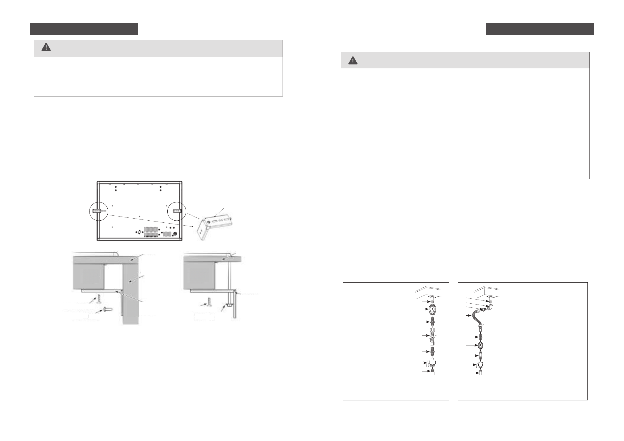
Ŗ!Important safety precautions
• Particular attention shall be given to the relevant requirements regarding ventilation.
• Please make this information available to the person installing the appliance as it could reduce
your installation costs.
• This appliance is to be installed and connected to gas supply only by an authorised person.
• Installation must comply with your local building and local gas authority codes and electricity
regulations.
• Failure to install the appliance correctly could invalidate any warranty or liability claims.
• This gas appliance is suitable for connection to natural gas and can convert to LPG only. If in
doubt, refer to the local gas network operator or gas supplier to confirm gas type at installation
site.
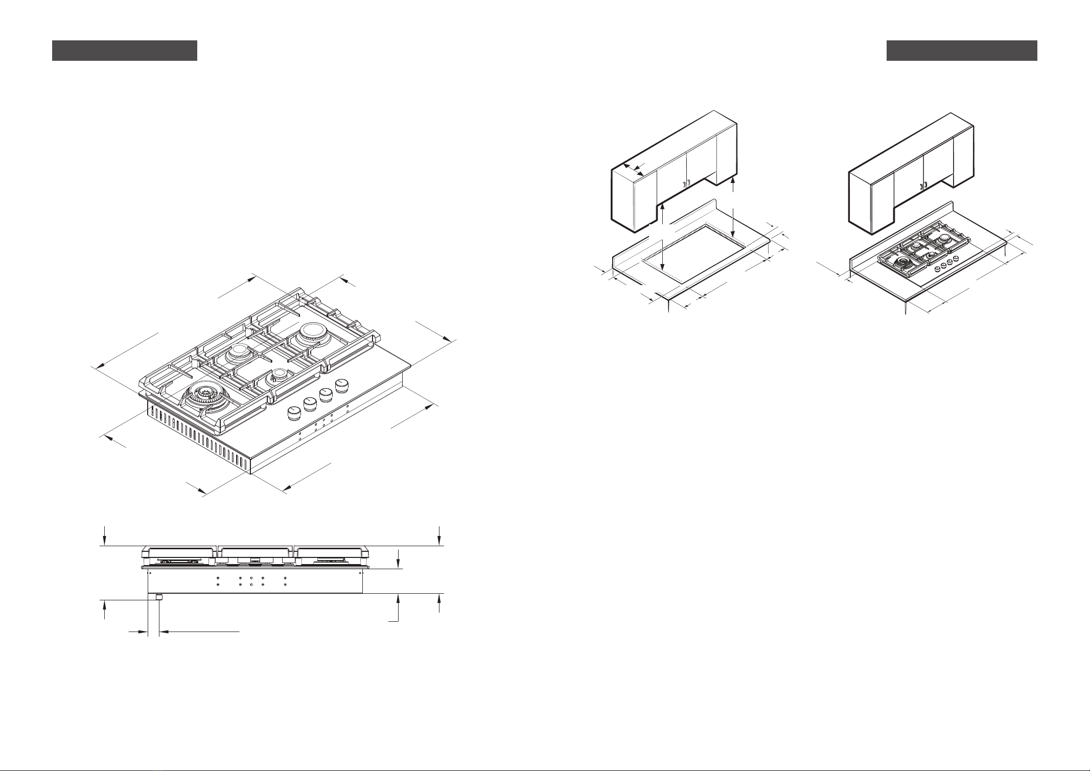
Ŗ!Before you install the appliance, please make sure that
• The local distribution conditions(nature of gas and pressure) and the adjustment of the appliance
are compatible. For adjustment conditions for this appliance check data plate for relevant gas
information.
• The supply connection point (gas shut-valve) is accessible after installation. The regulator
supplied with Natural gas appliances must be fitted to the appliance inlet.
Ŗ!When you install the appliance
• We do not recommend the use of a down-draught extractor fan with the appliance, as it may
distort the flame pattern, causing uneven heating and reduced cooking performance.
• Where this appliance is installed in marine craft or in caravans, it shall not be used as a space
heater.Only models fitted with the flame failure device can be fitted in marine craft. No combusti-
ble material or products should be placed on this appliance at any time.
• Do not spray aerosols in the vicinity of this appliance while it is in operation.
• If, after following the instructions given, the appliance cannot be adjusted to perform correctly,
please refer to the Service & Warranty book for warranty details and your nearest Authorised
Service Centre,or contact FOTILE Customer Care at:
Important safety information Important safety information
1-888-315-0366 (U.S.) [email protected]
1-844-315-0315 (CA) service@fotileca .com

-6--5-
Our products are only packaged using non-pollutant, environment-friendly, recyclable materials. We
urge you to cooperate by disposing of the packaging properly. Contact your local dealer or the compe-
tent local organizations for the addresses of collection, recycling and disposal facilities.
Never leave all or part of the packaging lying around. Packaging parts, and especially plastic bags, may
represent a suffocation hazard for children.
Your old appliance must also be disposed of properly. Important: deliver the appliance to your local
organization authorized to collect scrapped appliances. Proper disposal allows the intelligent recovery
of valuable materials.
Note: In this document, we take the image of model GLG30401-Y/GLG30401 as an example.
Compared with it, model GLG30301 does not have Simmer Burner and its control knob, and the
Center Grate is slightly different.
• Gas line shut-off valve
• Professional gas pipeline sealing materials that resists action of natural and propane gases
• Flexible metal appliance connector (3/8 NPT).
A 5-foot length is recommended for ease of installation but other lengths are acceptable.
Never use an old connector when installing a new cooktop.
• Flare union adapter for connection to gas supply line (3/4 or 1/2 NPT × 3/8 NPT).
• Flare union adapter for connection to pressure regulator on cooktop (1/2!NPT x 3/8 NPT).
• Liquid leak detector or soapy water.
Never leave packaging residues unattended in the house. Separate waste packaging materi-
als by type and consign them to the nearest separate disposal centre.
Ŗ!Materials You May Need
PACKAGE DISPOSAL INSTRUCTIONS - ENVIRONMENT POLICY
Packing List And ToolsImportant safety information
WHATʼS INCLUDED
Ŗ!Packing list and tools Ŗ!Tools You Will Need
Pencil and ruler
Safety Glasses
Phillips screwdriver
Open-end or
adjustable wrench
Saber Saw
1/8” Drill Bit & Electric
or Hand Drill
3/16” Flat-blade screwdriver
Pipe wrenches(2)
(one for backup)
Cooktop (1)
Nozzles for LPG (5) Installation Manual (1)
Pressure regulator (1)
User Manual (1) Warranty Card (1) Cover Sheet (1)
Wok Grate (1) Tea Kettle Grate (1) Panel mounting brackets (2)
Screws (6)
L8X2 L13X2 L70X2
Grates (3)
Burner Caps (4)Burner Heads (3)
GLG30301
Nozzles for LPG (6) Installation Manual (1)
Pressure regulator (1)
User Manual (1) Warranty Card (1) Cover Sheet (1)
Wok Grate (1) Tea Kettle Grate (1) Panel mounting brackets (2)
Screws (6)
L8X2 L13X2 L70X2
Cooktop (1)Burner Caps (5)Burner Heads (4)
GLG30401-Y/GLG30401
Grates (3)

-8--7-
Ŗ!Clearance Dimensions
Above the cooktop
The minimum safety distance given by the hood manufacturer must be maintained between the
cook top and the hood above it. See the installation instructions of the hood for these safety
measurements. If the hood manufacturerʼs instructions are not available or if flammable objects are
installed over the cook top (e.g. cabinets, utensil rail, etc.), a minimum safety distance of 30" (760
mm) must be maintained.
Minimum vertical clearances of 18 inches from top surface unit to side cabinets. Minimum horizontal
distance(s) from sides and back of appliance to adjacent vertical combustible walls extending above
the top panel, 12 inches from the left side, 12 inches from right side, 2 7/8 inches from rear wall.
Minimum clearance to combustible construction centered above cooking surface: vertical 30
inches, horizontal 30 inches. The unit overhead cabinet maximum depth: 13 inches. Minimum
horizontal distance from front edge of counter to front side of appliance, 1/4 inches.
If there are several appliances beneath a hood, and they have different minimum safety distances
always observe the largest distance.
Below the cooktop
All gas cooktop models require 7/16ʼʼ free area below cooktop height to combustible material.
Safety distances
1. Remove packing materials from the cooktop.
2. Make sure you have received all of the supplied parts shown above in the parts list.
3. Check that the cooktop is in good condition without damage during unpacking.
4. Check the dimensions and clearances (shown below), make sure the inside of the cabinet and the
cooktop do not interfere with each other.
Before you begin Before you begin
Product Dimensions (W x D x H) (inch):30 x 21 x 7 3/16
Cut-out Dimensions(W x D) (inch):28 1/2 x 19 5/8
Product Dimensions (W x D x H) (mm):762 x 533 x 182
Cut-out Dimensions(W x D) (mm):724 x 499
Ŗ!Product Dimensions
12 3/4" Min.
[323mm]
12 3/4" Min.
[323mm]
3 9/16" Min.
[91mm]
Rear wall
28 1/2" [724mm]
19 5/8" [499mm]
13" Max.
[330mm]
7 3/16"
[182mm]
6 5/16"
[160mm]
3 1/4"
[82mm]
1 7/16"
[37mm]
19 3/16"
[488mm]
21"
[533mm]
28 1/4"
[718mm]
30"
[762mm]
2 7/8"Min
[73mm]
12"Min
[305mm]
12"Min
[305mm]
1/4"Min
[6mm]
Rear wall
18" Min.
[457mm]
30" Min.
[762mm]
1" Min
[25.4mm]

-10--9-
WARNING
Electrical outlet 12” (30.5 cm) minimum below countertop
All gas models are equipped with a power cord with an equipment-grounding conductor and a
grounding plug.
A 120-Volt, 60-Hz, AC, approved electrical service with 20-amp circuit breaker or time-delay fuse
is required for all U.S. and Canadian models.
The plug must be firmly plugged into a three-prong outlet that is properly installed and grounded
in accordance with local codes or, in the absence of local codes, with the National Electrical Code,
NFPA 70 or the Canadian Electric Code, CSA C22.1-02. In the event of a malfunction or break-
down, grounding will decrease the risk of electrical shock by providing a path for the electric
current.
Provide adequate gas supply
Explosion Hazard
Use a new CSA/ETL International approved gas supply line.
Install a shut-off valve.
Securely tighten all gas connections.
If connected to LP, have a qualified person make sure gas pressure does not exceed 14ʼʼ
(36cm) water column.
Examples of qualified person include:
Licensed heating personnel
Authorized gas company personnel, and
Authorized service personnel.
Failure to do so can result in death, explosion, or fire.
WARNING
The pressure regulator located at the inlet of the cooktop manifold must remain in the supply
line regardless of whether natural or LP gas is being used.
This cooktop is designed to operate at a pressure of 4in (10cm) of water column on natural gas or 10in
(25cm) of water column on LP gas.
Make sure you are supplying your cooktop with the type of gas for which it is designed. Do not attempt
to convert the appliance from the gas specified in this manual to a different gas without consulting the
gas supplier.
This cooktop is convertible for use on natural or propane gas. If you decide to use this cooktop on LP
gas, conversion must be made by a qualified LP installer before attempting to operate the cooktop.
For proper operation, the pressure of natural gas supplied to the regulator must be between 4in and
10in (10cm and 25cm) of water column.
For LP gas, the pressure supplied must be between 10in and 13in (25cm and 33cm) of water column.
When checking for proper operation of the regulator, the inlet pressure must be at least 1in (2.5cm)
greater than the operating (manifold) pressure as given.
WARNING
Electrical Shock Hazard
Plug into a grounded 3 prong outlet.
Do not remove ground prong.
Do not use an adapter.
Do not use an extension cord.
Failure to follow these instructions can result in death, fire, or electrical shock.
Installation requirements Installation requirements
Ŗ!Gas supply requirements Ŗ!Electrical requirement

-12--11-
• FOTILE gas cooktops are manufactured and shipped to be used with natural gas. If you want to
use LPG, please convert before using.
• To prevent gas leaks, please use professional gas pipe sealing materials on all male (external)
pipe threads.
• Attach the gas pressure regulator (included with the cooktop) to the cooktop pipe nipple inlet. For
tight installations, the regulator may be installed upstream from the pipe nipple, anywhere
between the shut-off valve and the cooktop. For best performance, minimize gas pressure loss by
attaching the regulator as close as possible to the cooktop gas inlet.
• When all connections have been made, make sure all cooktop controls are in the off position and
turn on the main gas supply valve.
• Use Soap-suds at all joints and connections to check for leaks in the system.
• Tighten all connections if necessary to prevent gas leakage in the cooktop or supply line.
Ŗ!Step 1: Installing the cooktop
• Locate electrical outlet and gas shut-off valve beneath the cabinet.
• Insert the cooktop centered into the cutout opening. Make sure the front edge of the countertop
is parallel to the cooktop. Make final check that all required clearances are met.
* Be careful that the ignition needle/thermocouple is not damaged by inserting.
• Choose installation method 1 or method 2 shown below to secure the cooktop to the countertop
using the two provided hold-down brackets as shown.
Please read the following instructions, as well as the Important Safety Instructions section at the
front of this manual, completely and carefully BEFORE installing and/or operating the gas cooktop.
Improper installation, adjustment, service, or maintenance can cause personal injury or property
damage.
WARNING
Shut off the main gas supply valve before disconnecting the old cooktop and leave it off until the new
hookup has been completed. Donʼt forget to relight the burner on other gas appliances when you turn
the gas back on.
Because hard piping restricts movement of the cooktop, the use of a CSA International-certified flexible
metal appliance connector is recommended unless local codes require a hard-piped connection.
Never use an old connector when installing a new cooktop. If the hard-piping method is used, you
must carefully align the pipe; the cooktop cannot be moved after the connection is made.
Tighten all connections if necessary to prevent gas leakage in the cooktop or supply line.
Check for gas leaks: To prevent death, personal injury, explosion, and/or fire hazard, DO NOT use a
flame to check for gas leaks. When using test pressures greater than ½ psig to pressure-test the gas
supply system of the residence, disconnect the cooktop and individual shut-off valve from the gas
supply piping. When using test pressures of ½ psig or less to test the gas supply system, simply
isolate the cooktop from the gas supply system by closing the individual shut-off valve.
Ŗ!Step 2: Connecting the cooktop to gas supply
Installation instructions Installation instructions
88
70M5
13
WARNING
Installation Method 1 Installation Method 2
No appliance/obstructions
below cooktop
A
B
C
D
E
F
G
A. 1/2” NPT male pipe thread
B. Regulator provided with
unit:
• Outlet - 1/2” NPT
female pipe thread
• Inlet - 1/2” NPT female
pipe thread
C. Adapter
• Outlet - 1/2” NPT female
pipe thread
• InIet - 3/8” NPT female
pipe thread
D. Flexible connector
E. Adapter
F. Manual shut-off valve
G. Gas pipe
Suggested installation to avoid interference
below cooktop
A
B
C
D
E
F
G
H
I
A. 1/2” NPT male pipe thread
B. Elbow
C. Adapter
• Outlet - 1/2” NPT female
pipe thread
• InIet - 1/2” NPT female pipe
D. Flexible connector (allows passage
through cabinet wall)
E. Adapter
F. Regulator provided with unit:
• Outlet - 1/2” NPT female
pipe thread
• Inlet - 3/8” NPT female pipe thread
G. Gas pipe
H. Manual shut-off valve
I. Gas pipe
ᠲᄪႢᢣ
Panel mounting brackets
Countertop
Side wall of
undercounter
cabinet
Hold down
bracket
Hold down
bracket
M4 L screw M4 L screw
L screw
M4 L screw
Countertop
ChassisChassis

-14--13-
WARNING
The electrical system, including the power cord, is preinstalled and
prewired at the factory. Altering any part of this system may result in a
short or overload.
Ŗ!Step 3: Electrical connections
• All gas cooktops come with a power cord. The power cord is connected
to the bottom of the cooktop
• Plug in the power cord. Make sure the outlet meets local or national
electrical codes
1. Hold the burner head so the shiny silver side is facing down. Find the small hole in the burner
head as noted in this picture.
Tri-Ring burner assembly:
2. Place the burner head onto the cooktop surface so that “hole A” gets inserted into “pin B” on
the cooktop. Make sure “Pin B” is firmly seated into “hole A” on the Burner Head. If not,
remove the burner head and try it again. Please refer to the pictures below for this step.
3. Place the lined part of outer burner cap to fit in the lined part of the burner head. Shake the
outer burner cap gently to check if it is firmly seated (you will be able to rotate the outer burner
cap, but it should be firmly seated in the burner head.)
Burner components installation
A
B
4. Next, place the inner burner cap on the burner head and make sure it is firmly set by gently
sliding it from side to side.
Installation instructions Installation instructions
Ŗ!Step 4: Burner components and grate installation
A
B
C
D
•Pressure regulator installation
Install the pressure regulator with the arrow pointing in the direction toward the bottom of
the cooktop base and in a position where you can reach the regulator access cap.
A. Access cap
B. Rear of cooktop
C. Gas pressure regulator
D. Up arrow.The arrow is on the
bottom of the pressure regulator.
L:18000BTU, Versatile Tri-Ring Burner
Outer Burner Cap Burner Head Inner Burner Cap
R:13200BTU,Rapid Burner
Burner Cap
\90
Burner Head
CR:5800BTU,Semi Rapid Burner
Burner Cap
\75
Burner Head
CF:3000BTU Simmer Burner
Burner Cap
\50
Burner Head

-16--15-
5. Check if the burner head/burner cap is firmly seated. If the burner head/cap is not level or is
unstable, you must take it off, and reinsert it again.
Ŗ!Install the grates
1. Identify 13200BTU/5800BTU/3000BTU burner head and burner cap by size.
Other burner assembly:
2. Hold the burner head, then find the gap “C” and ignition needle “D”, make it on the same side.
3. Place the burner head with the gap “C” next to the ignition needle “D” and make sure the burner
head is firmly seated.
C
D
4. Place the lined part of burner cap to fit in the lined part of the burner head. Shake the burner
cap gently to check if it is firmly seated.
5. Check if the burner head/burner cap is firmly seated. If the burner head/cap is not level or is
unstable, you must take it off, and reinsert it again.
Installation instructions Installation instructions
The three cooktop grates are designed to fit in specific positions on the cooktop. For maximum
stability, these grates should only be used in their proper positions.
1. Take out the three grates and find the center grate first. Note, the left and right grids are exactly
the same.
2. Gently lower the legs of the center grate so they rest in the center grate dimples of the cooktop.
3. Take the other two grates and make sure the thicker sides of the grates face the outer left and
right sides of the cooktop.
4. Gently lower the legs of the grates into the dimples of the cooktop. When properly installed,
neither grate will make contact with the overhangs of the center grate.
To properly setup your cooking grates, please follow these steps:
Left/Right Grate(same) Center Grate
2
1
Thicker sides
Thicker sides
WARNING
Do not try to remove the grate until the cooking grates and cooktop
surface have completely cooled down.
11
2

Nota
Make sure the knob is in the "OFF" position before starting operation, if it is not, turn the knob
clockwise.
Ŗ!Step 5: Check the ignition and flame quality
-18--17-
All FOTILE gas cooktops are manufactured and shipped to be used with natural gas. The cooktop
are also shipped with LP Conversion Kits (a set of properly-sized burner orifices, the pressure
regulator could use for both natural gas and LP), so the cooktop can be converted to be used with LP
gas. Please follow instruction when converting.
LP Conversion Kits
Ŗ!Requipped tools
1. Disconnect electrical power to the cooktop. Unplug the cooktop power cord, trip the circuit
breaker, or remove the fuse from the fuse box.
2. Shut off the gas supply to the cooktop. Close the manual shut-off valve to the cooktop.
To convert your cooktop for use with LP gas, perform the following steps
and procedures:
LP Conversion Instructions
Check the ignition
• This appliance is equipped with an electronic ignition device. Simply press the knob down-
ward and turn it counterclockwise to HI. Then, you will hear clicking sounds, which indicates
proper operation of the ignition system.
• Once air is purged from the supply line, the burner should light within 3-5 seconds, and the
clicking sounds will stop.
• After the burner lights, rotate the knob to your desired position.
• Try each burner in succession until all burners have been checked.
Check the flame quality
• Determine the quality of flames visually. Normal burner flames should look like following 2
pictures.
• Long, bright yellow flames are not normal. Normal flames may show signs of an orange tint
when well heated or signs of flickering orange due to particles in the gas or air.
Installation instructions
BURNER BTU RATE Orifice size [mm]
BURNER ORIFICE SIZES AND OUTPUT RATINGS
(LP Gas [Propane] 10 in WCP)
Versatile Tri-Ring Burner
Semi Rapid Burner
Simmer Burner
Rapid Burner
15000
4500
3000
9100
In:0.6/Out:0.7(2 pcs)
0.65
0.55
0.92
Adjustable wrench 9/32” open-end wrench Nut drivers:9/32”or 7mm
Phillips screwdriver 3/16” Flat-blade screwdriver
Woks are often used for stir-frying and pan frying. To use a Wok, you need to attach the Wok
Grate so your Wok will sit on the burner properly and safely.The tea kettle grate is usually used
for small pans smaller than 6in.
1.the wok grate and the tea kettle grate can only be placed on the versatile tri-Ring burner cook-
ing grate,or the rapid burner cooking grate
2. Do not use both the wok grate and the tea kettle grate on the same burner.
Ŗ!Wok Grate & Tea Kettle Grate
Wok Grate Tea Kettle Grate Nozzles for LPG (5)
GLG30301
Nozzles for LPG (6)
GLG30401-Y/GLG30401

-20--19-
Step 1: Lift off the burner caps and burner heads from the cooktop burner manifold cups.
Save these orifices and note their positions for future conversions back to natural gas.
Ŗ!1. Following below instruction to change pressure regulator
from natural gas to LP
Ŗ!2. Follow the instructions below to change the burner orifices
from Natural Gas to LP
WARNING
This conversion kit shall be installed by a qualified service agency in accordance with the manu-
facturerʼs instructions and all applicable codes and requirements of the authority having jurisdic-
tion. If the information in these instructions is not followed exactly, a fire, explosion or production
of carbon monoxide may result causing property damage, personal injury or loss of life. The
qualified service agency is responsible for the proper installation of this kit. The installation is not
proper and complete until the operation of the converted appliance is checked as specified in the
manufacturerʼs instructions supplied with the kit.
Caution: Before proceeding with the conversion, shut off the gas supply to the appliance prior to
disconnecting the electrical power.
B
Unscrew the threaded pin
from top hat
Configuration for
natural gas
D
E
Configuration for
LPG
H
Unscrew the top hat
nut from the regulator
Upturn threaded pin
and screw pin back
Refit the top hat nut
assembly to the regulator
A
F
C
G
LP Conversion Instructions
Orifice size
0.7mm
0.6mm
0.7mm
Orifice size(mm)
Semi Rapid Burner 0.65
Simmer Burner 0.55
Rapid Burner 0.92
LP Conversion Instructions
Step 2: Using a 9/32" or 7mm nut drive, remove the burner orifice from the bottom of the
13200BTU/5800BTU/3000BTU burner manifold cup. And replace with the LP burner nozzles,
then screw up clockwise.
Step 3: Using Phillips screwdriver take off the bracket, then using a 9/32” or 7mm open-end
wrench, remove the burner orifice from the bottom of center burner manifold cup. And replace the
LP burner nozzles.
Burner cap
Burner head
Burner cup

Step 4: Take off all the knobs.
Step 6: Put the burner heads and burner caps into burner manifold cup.
Step 8: Put the cooktop panel, burner heads, burner caps, knobs, and grate back into
place correctly.
Step 9:Please refer to page 9 of the installation manual to make sure the air supply
pressure is correct, refer to page 12 to check that the piping connections meet the
requirements, and check for gas leaks, refer to page 17 to check the ignition system
and flame quality.
3/16” flat-blade
screwdriver
bypass screw
-21- -22-
Step 7: Adjust bypass screw
Put the knobs back to the cooktop, open the gas shut-off valve, and try ignition. Turn the knob
into small flame(270°),then use a 3/16” flat-blade screwdriver to adjust the bypass screws clock-
wise. Make sure that the flame is small enough but will not go out within 1 minute (flame reach
the top of the thermocouple). If the flame goes out, then adjust the bypass screws counterclock-
wise and repeat the test.Use same way to adjust bypass screw for 5 burners.
Thermocouple
LP Conversion Instructions LP Conversion Instructions
Step 5: Disassemble the panel
Using Phillips screwdriver unscrews the panel screws, then lift off the panel.

Every effort has been made to ensure that the information given in this manual is correct at
the time of printing. However, due to the continuous product improvement, FOTILE
reserves the right to make changes to the products and technical data without prior notice.
Manufactory: Ningbo Fotile Kitchenware Co., Ltd.
No.218 Binhai 2 Road, Hangzhou Bay New District, Cixi, Zhejiang, China
WWW.FOTILEGLOBAL.COM
Estufas de gas
Lea todas las instrucciones
antes de usar este aparato
GLG30301 GLG30401-Y GLG30401
Manual de
instalación

-2--1-
Contenido
Información Importante de Seguridad
Lista de embalaje y herramientas
de instalación
Inspección antes de la instalación
Dimensiones del producto
Requisitos del entorno de instalación
Requerimientos de instalación
Instrucciones de instalación
Instalación de la estufa
Conexión al suministro de gas
Conexiones eléctricas
Gura de montaje de hornilla instalación del
soporte de la olla
Verifique el encendido y la calidad de la llama
Instrucciones de conversión de gas
licuado de petróle
2
6
7
7
9
8
11
13
12
13
18
17
11
Lea todas las instrucciones detenidamente antes de usar este
aparato. Guarde este manual. No lo pierdas.
Hemos proporcionado mucha información importante de seguridad en este manual y en su
electrodoméstico. Asegúrese de leer y seguir toda la información de seguridad.
La información de seguridad mencionará los riesgos potenciales, cómo reducir la posibilidad de
lesiones y las posibles consecuencias de no seguir las instrucciones.
Siga estrictamente las instrucciones de uso, de lo contrario, puede enfren-
tar peligro inmediato para la vida o lesiones graves.
Siga estrictamente las instrucciones de uso, de lo contrario,
puede enfrentar peligro para la vida o lesiones graves.
Esta es una señal de advertencia de seguridad.
Este letrero le recuerda el peligro potencial de causar víctimas.
Toda la información de seguridad seguirá las señales de advertencia de seguridad,
incluidas las palabras "PELIGRO" o "ADVERTENCIA".
Los significados de estas palabras son los siguientes:
Su seguridad y la seguridad de los demás son muy importantes.
PELIGRO
ADVERTENCIA
ADVERTENCIA
:PNHLZ[YPJ[HTLU[LSHPUMVYTHJP}UKLLZ[LTHU\HSKLSVJVU[YHYPVWVKYxHWYV]VJHY\UPUJLU
KPVV\UHL_WSVZP}USVX\LWYV]VJHYxHSHWtYKPKHKLWYVWPLKHKSLZPVULZWLYZVUHSLZVWLSPNYV
WHYHSH]PKH
¶5VHSTHJLULUP\ZLNHZVSPUH\V[YVZNHZLZ`SxX\PKVZPUMSHTHISLZJLYJHKLLZ[LLX\PWV\
V[YVLX\PWV
¶8<i/(*,9:0/<,3,(.(:!
5VLUJPLUKHUPUNULX\PWV
5V[VX\LUPUNUPU[LYY\W[VYLStJ[YPJV
5V\ZLLS[LStMVUVLUZ\LKPMPJPV
<ZLLS[LStMVUVKLZ\]LJPUVWHYHSSHTHYHZ\WYV]LLKVYKLNHZKLPUTLKPH[V:PNHSHZ
PUKPJHJPVULZKLSWYV]LLKVYKLNHZ
:PUVW\LKLJVU[HJ[HYHSWYV]LLKVYKLNHZSSHTLHSKLWHY[HTLU[VKLIVTILYVZ
¶3HPUZ[HSHJP}U`LSTHU[LUPTPLU[VKLILUZLYYLHSPaHKVZWVYPUZ[HSHKVYLZJHSPMPJHKVZ
VYNHUPaHJPVULZKLTHU[LUPTPLU[VVWYV]LLKVYLZKLNHZ
Información Importante de Seguridad

-4--3-
ADVERTENCIA
Precauciones de instalación
Ŗ!Precauciones de seguridad importante
• Se prestará atención especial a los requisitos relevantes con respecto a la ventilación.
• Ponga esta información a disposición de la persona que instala el dispositivo, ya que podría
reducir los costos de instalación.
• Este electrodoméstico debe ser instalado, conectado a electricidad y el suministro de gas solo
por profesionales.
• La instalación debe cumplir con las normas locales de construcción y de las autoridades locales
de gas y las regulaciones de electricidad.
• Si no instala el aparato correctamente, podría invalidar la garantía o el reclamo.
• Solo aplicable al gas natural o al gas licuado (la configuración de fábrica es para gas natural, para
el uso de gas licuado se necesita ser convertido). En caso de duda, consulte a su proveedor local
de gas.
Ŗ!Antes de instalar el dispositivo, asegúrese de queǖ
• El gas local y la presión son compatibles con este producto. Para obtener información sobre el
gas compatible, consulte la placa de identificación del producto.
• Después de la instalación, la válvula del interruptor de gas debe ser fácilmente accesible y la
válvula reductora de presión debe instalarse en la entrada de gas del producto.
Ŗ!Cuando instale el dispositivoǖ
• No recomendamos el uso de un ventilador extractor de tiro descendente con este producto, ya
que puede distorsionar el patrón de la llama, causando un calentamiento desigual y un
rendimiento de cocción reducido.
• Solo los modelos equipados con el dispositivo de falla de llama se pueden instalar en barcos o
vehículos recreativos, pero no pueden usarse como calentadores.
• No coloque materiales o productos inflamables sobre el producto. Cuando el producto esté
trabajando, no rocíe aerosoles cerca.
• Si el producto aún no puede funcionar normalmente después de operar de acuerdo con este
manual, comuníquese con el Servicio al Cliente de FOTILE:
ADVERTENCIA
Las fugas de gas no se pueden detectar con precisión solo por el olor.
Los proveedores de gas recomiendan que usted use un detector de gas aprobado por UL o CSA.
Póngase en contacto con su proveedor de gas para obtener más información.
ADVERTENCIA
*\HUKV\ZLLZ[LHWHYH[VWHYHJVJPUHYUVSVKLQLKLZH[LUKPKV
9LZWL[LLZ[YPJ[HTLU[LLZ[HKLJSHYHJP}UKLHK]LY[LUJPHKLSVJVU[YHYPVWVKYxHWYV]VJHY
\UPUJLUKPVV\UHL_WSVZP}USVX\LWYV]VJHYxHSHWtYKPKHKLWYVWPLKHKSLZPVULZWLYZV
UHSLZVWLSPNYVWHYHSH]PKH
,UJHZVKLPUJLUKPVHJJPKLU[HSTHU[tUNHZLHSLQHKVKLLZ[LLX\PWV`SSHTLHSKLWHY[H
TLU[VKLIVTILYVZKLPUTLKPH[V5VPU[LU[LL_[PUN\PYM\LNVZKLWL[Y}SLVJVUHN\H
IMPORTANTE
No instale un sistema de ventilación que expulse aire hacia la estufa de gas. Este tipo de sistema
de ventilación puede causar problemas de ignición y combustión de la estufa de gas, lo que puede
provocar lesiones personales o accidentes.
ADVERTENCIA DE LA PROPUESTA 65 DEL ESTADO DE
CALIFORNIA
ADVERTENCIA
Este producto contiene uno o más productos químicos que el Estado de California sabe que
causan cáncer, defectos de nacimiento u otros daños reproductivos.
Las estufas de gas pueden causar una exposición de bajo nivel a algunas de estas sustancias,
incluidos el benceno, el monóxido de carbono, el formaldehído y el hollín, que se producen princi-
palmente por la combustión incompleta de gas natural o combustible de propano.
Abrir ventanas o usar ventiladores o campanas de ventilación puede minimizar la exposición a
tales sustancias.
ESTADO DE MASSACHUSETTS
En el estado de Massachusetts, se aplican las siguientes instrucciones de instalación:
• Las instalaciones y reparaciones deben ser realizadas por un contratista, plomero o instalador
de gas calificado o con licencia calificado por el Estado de Massachusetts.
• Si usa una válvula de bola, debe ser del tipo de mango en T.
• Un conector de gas flexible, cuando se usa, no debe exceder 3 pies.
Información Importante de Seguridad
Peligro de descarga eléctrica
El incumplimiento de las instrucciones puede causar descargas eléctricas, lesiones o
la muerte.
Peligro de corte
Tenga cuidado, los bordes del panel son afilados.
Si no se tiene precaución, se pueden causar lesiones o cortes.
Información Importante de Seguridad
1-888-315-0366 (U.S.) [email protected]
1-844-315-0315 (CA) service@fotileca .com

-6--5-
Nuestros productos solo se empaquetan con materiales ecológicos, no contaminantes y reciclables.
Esperamos que manejes el embalaje correctamente. No deseche todo o parte del embalaje en ningún
lado. Las piezas del embalaje, especialmente las bolsas de plástico, pueden causar un peligro de
asfixia para los niños.
El producto que reemplazó también esperamos que lo maneje adecuadamente. Puede entregar el
equipo reemplazado a la agencia local de reciclaje de equipos de desecho. El manejo adecuado puede
recuperar efectivamente materiales valiosos.
Nota: En este documento, tomamos la imagen del modelo GLG30401-Y/GLG30401 como ejemplo.
Comparado con él, el modelo GLG30301 no tiene quemador rápido y su mando de control, y la
Rejilla Central es ligeramente diferente.
• Válvula de interruptor de gas
• Material profesional de sellado de tuberías de gas resistente a la acción del gas natural y el
propano.
• Conector de metal flexible para electrodomésticos (3/8 NPT).
Se recomienda una longitud de 5 pies para facilitar la instalación, pero se aceptan otras longi-
tudes. Nunca use un conector viejo cuando instale una estufa nueva.
• Adaptador de unión acampanada para la conexión a la línea de suministro de gas (3/4 pulgada
o1/2 NPT × 3/8 NPT).
• Adaptador de unión acampanada para la conexión al regulador de presión en la estufa (1/2!
NPT x 3/8 NPT).
• Detector de fugas de líquido o agua jabonosa.
Nunca deje los residuos de embalaje desatendidos en la casa. Separe los materiales de
embalaje de desecho por tipo y entréguelos al centro de procesamiento más cercano.
Ŗ!Herramientas que pueden ser necesarias
INSTRUCCIONES PARA EL DESECHO DE PAQUET-
ES-POLÍTICA DE MEDIO AMBIENTE
Lista de embalaje y herramientas de instalación
Ŗ!Herramientas necesarias para la instalación.
Lápiz y regla
Lentes de seguridad
Llave de tubo (2)
(una de repuesto)
3/16” Destornillador
ranurado
Sierra de cuchillo
Broca de 1/8 de
pulgada y taladro
eléctrico o taladro
manual
Destornillador Phillips
Llave de boca abierta
o llave ajustable
Información Importante de Seguridad
Ŗ!Lista de empaque
Estufa de gas (1)
Boquilla de gas
licuado de petróleo (5)
Manual de
instalación (1)
Regulador de presión (1)
User Manual (1) Tarjeta de
garantía (1)
Guía de montaje
de hornilla(1)
Rejillas del Wok (1) Rejilla para tetera (1) Soporte de montaje
en panel (2)
Tomillo (6)
L8X2 L13X2 L70X2
soporte de la olla (3)
Tapa de hornilla (4)Cabeza de hornilla (3)
GLG30301
Boquilla de gas
licuado de petróleo (6)
Manual de
instalación (1)
Regulador de presión (1)
User Manual (1) Tarjeta de
garantía (1)
Guía de montaje
de hornilla(1)
Rejillas del Wok (1) Rejilla para tetera (1) Soporte de montaje
en panel (2)
Tomillo (6)
L8X2 L13X2 L70X2
Estufa de gas (1)Tapa de hornilla (5)Cabeza de hornilla (4)
GLG30401-Y/GLG30401
soporte de la olla (3)

-8--7-
Ŗ!Requisitos del entorno de instalación
La distancia de seguridad mínima proporcionada por el fabricante de la campana extractora debe
mantenerse entre la estufa incorporada y la campana extractora que se encuentra sobre ella. Para
conocer las dimensiones de seguridad relacionadas, consulte las instrucciones de instalación de la
campana extractora. Si el fabricante de la campana extractora no especifica o hay objetos inflam-
ables instalados encima de la estufa (como armarios, perchas, etc.), la distancia mínima de seguri-
dad es de 30 pulgadas (760 mm).
El espacio vertical mínimo desde la parte superior del producto hasta el gabinete lateral es de 18
pulgadas, la distancia horizontal mínima desde la parte posterior del producto hasta la pared
vertical es de 2 7/8 pulgadas, y la distancia horizontal mínima desde el lado del producto hasta los
combustibles en los lados izquierdo y derecho es de 12 pulgadas, La distancia horizontal mínima
desde el borde frontal del gabinete al lado frontal del producto es de 1/4 pulgada.
Si hay varios electrodomésticos debajo de la campana extractora y sus distancias máximas de
seguridad no son las mismas, observe siempre la distancia más grande.
Debajo de la estufa
Todos los modelos de estufas requieren un espacio libre de 7/16 pulgadas desde el fondo hasta los
materiales combustibles.
Sobre la estufa
1. Retire los materiales de embalaje de la estufa.
2. Asegúrese de haber recibido todas las piezas incluidas en la lista de empaque.
3. Compruebe que la estufa esté en buenas condiciones sin daños.
4. Compruebe las dimensiones y los requisitos del entorno de instalación (que se muestran a continu-
ación), asegúrese de que el interior del gabinete y la estufa no interfieran entre sí.
Inspección antes de la instalación
Ŗ!Dimensiones del producto
Inspección antes de la instalación
Dimensiones del producto(W x D x H) (inch):30 x 21 x 7 3/16
Dimensiones del agujero(W x D) (inch):28 1/2 x 19 5/8
Dimensiones del producto (W x D x H) (mm):762 x 533 x 182
Dimensiones del agujero(W x D) (mm):724 x 499
7 3/16"
[182mm]
6 5/16"
[160mm]
3 1/4"
[82mm]
1 7/16"
[37mm]
19 3/16"
[488mm]
21"
[533mm]
28 1/4"
[718mm]
30"
[762mm]
12 3/4" Min.
[323mm]
12 3/4" Min.
[323mm]
3 9/16" Min.
[91mm]
Rear wall
28 1/2" [724mm]
19 5/8" [499mm]
13" Max.
[330mm]
2 7/8"Min
[73mm]
12"Min
[305mm]
12"Min
[305mm]
1/4"Min
[6mm]
Rear wall
18" Min.
[457mm]
30" Min.
[762mm]
1" Min
[25.4mm]

-10--9-
ADVERTENCIA
La toma de corriente se encuentra al menos a 12 pulgadas (30.5 cm) debajo de la encimera del
gabinete.
El producto es adecuado para corriente alterna de 120V, 60Hz.
El cable eléctrico de la estufa está equipado con un conductor de conexión a tierra. Se debe usar
un enchufe de tres clavijas y el enchufe se debe instalar y conectar a tierra correctamente de
acuerdo con los códigos locales o, en ausencia de códigos locales, con el Código Eléctrico Nacio-
nal, NFPA 70 o el Código Eléctrico Canadiense, CSA C22.1 -02. Si el producto falla o está
dañado, una conexión a tierra adecuada puede reducir el riesgo de descarga eléctrica.
Proporcionar un suministro de gas adecuado.
Peligro de explosión
Use la nueva línea de suministro de gas aprobada por CSA / ETL.
Instale la válvula del interruptor de gas.
Apriete bien todas las conexiones de gas.
Si está conectado a gas licuado de petróleo, haga que personal calificado se asegure de que
la presión de gas no exceda las 14 pulgadas (36 cm) de la columna de agua.
Deje que los profesionales operen, de lo contrario puede causar la muerte, explosión o
incendio.
Los profesionales incluyen:
Personal de calefacción con licencia, personal autorizado de la compañía de gas y personal
de mantenimiento autorizado.
ADVERTENCIA
Independientemente de si se utiliza gas natural o gas licuado de petróleo, la válvula reducto-
ra de presión debe instalarse en la entrada de aire.
La presión de gas adecuada para que funcione la estufa es: columna de agua de 4 pulgadas (10
cm) de gas natural o columna de agua de 10 pulgadas (25 cm) de gas licuado de petróleo.
La estufa puede usar gas natural o gas licuado. Pero la producción está configurada para gas
natural, si necesita usar gas licuado, solicite a los profesionales que lo conviertan. No use otro tipo
de gas.
Para que la estufa funcione normalmente, la presión de suministro de gas natural debe estar entre
4 pulgadas y 10 pulgadas (10 cm y 25 cm) de columna de agua, y la presión de suministro de gas
licuado debe estar entre 10 pulgadas y 13 pulgadas (25 cm y 33 cm) de columna de agua.
Al verificar si la válvula reguladora de presión funciona normalmente, la presión de entrada debe
ser al menos 1 pulgada (2.5 cm) mayor que la presión de trabajo (múltiple) como se indica.
ADVERTENCIA
Peligro de descarga eléctrica
Enchúfelo a una toma de corriente con conexión a tierra de 3 terminales.
No quite el terminal de tierra.
No use un adaptador.
No utilice un cable de extensión.
El incumplimiento de estas instrucciones puede provocar la muerte, incendio o descarga eléctrica.
Requerimientos de instalación Requerimientos de instalación
Ŗ!Requerimientos de suministro de gas Ŗ!Requisito eléctrico

-12--11-
• Las estufas de gas FOTILE se fabrican y envían para usarse con gas natural. Si desea usar gas
licuado de petróleo, conviértalo antes de usarlo.
• Para evitar fugas de gas, utilice UN material de sellado profesional para tuberías de gas.
• Conecte la válvula reguladora de gas (incluida en la estufa) a la entrada de la junta del tubo de la
estufa. La instalación es compacta y el regulador se puede instalar en cualquier lugar entre la
válvula de cierre y la estufa incorporada aguas arriba de la tubería corta. Para obtener el mejor
rendimiento, el regulador se puede colocar lo más cerca posible de la entrada de gas de la estufa
incorporada para minimizar la pérdida de presión de gas.
• Después de completar todas las conexiones, asegúrese de que todas las perillas de la estufa
estén en la posición cerrada y abra la válvula del interruptor de gas.
•Use detectores de fugas de líquido en todas las juntas y conexiones para verificar si hay fugas de gas.
Ŗ!Paso 1: Instalación de la estufa
• Confirme la posición de la válvula del interruptor de gas y la toma de corriente debajo del
gabinete.
• Inserte la estufa centrada en la abertura del recorte y asegúrese de que el borde frontal de la
encimera esté paralelo a la estufa.
• Haga una verificación final de que se cumplan todos los requisitos del entorno de instalación.
* Tenga cuidado de que la aguja de encendido o termopar no se dañe durante la instalación.
• Como se muestra en la figura, use 2 soportes de montaje en panel para fijar la estufa al gabinete.
Antes de instalar u operar la estufa, lea atentamente las instrucciones de seguridad importantes
anteriores y siga estrictamente los pasos a continuación para instalarla. La instalación, reparación
o mantenimiento incorrectos pueden causar lesiones personales o daños a la propiedad.
ADVERTENCIA
Cierre la válvula del interruptor de gas antes de desconectar la estufa vieja y déjela apagada hasta
que se haya completado la nueva conexión.
Debido a que las tuberías rígidas restringen el movimiento de la estufa, se recomienda el uso de un
conector de electrodomésticos de metal flexible certificado por CSA International a menos que los
códigos locales requieran una conexión por tubería rígida.
Nunca use un conector viejo cuando instale una estufa nueva. Si se utiliza el método de tubería dura,
debe alinear cuidadosamente la tubería, la estufa no se puede mover después de realizar la conex-
ión,apriete todos los adaptadores para evitar fugas de aire de la estufa o la línea de suministro.
Compruebe si hay fugas de gas: para evitar la muerte, lesiones personales, explosiones y / o incendi-
os, no use llamas para comprobar si hay fugas de gas. Cuando utilice una presión de prueba mayor a
1/2 psig para probar el sistema de suministro de gas residencial, desconecte la estufa y la válvula del
interruptor de gas de la línea de suministro de gas. Cuando use 1/2 psig o una presión de prueba más
baja para probar el sistema de suministro de gas, simplemente cierre la válvula del interruptor de gas.
Ŗ!Paso 2: Conexión al suministro de gas
Instrucciones de instalación Instrucciones de instalación
ADVERTENCIA
métodos de instalación 1 métodos de instalación 2
A
B
C
D
E
F
G
A. 1/2” NPT male pipe thread
B. Válvula reguladora el tamaño
de conector es:
• Entrada -1/2ʼʼRosca interna
• Salida -1/2ʼʼ Rosca interna
C. Adaptador
• Conector de salida -1/2 "
NPT,conectado a la válvula
reguladora
• Conector de entrada -3/8 ''
NPT, conectado con
tubería flexible
D. Tubo de conexión flexible
E. Adaptador
F. Válvula de cierre manual de
gas
G. Tubería de gas
A
B
C
D
E
F
G
H
I
A. 1/2ʼʼ NPT Junta de tubería de entrada de
aire
B. Conector del codo de 90 grados
C. Adaptador
• Conector de salida -1/2 " NPT,conectado
a la válvula reguladora
• Conector de entrada -3/8 '' NPT,
conectado con tubería flexible
D. Tubo de conexión flexible (Longitud
suficiente para pasar a través del orificio
de la pared)
E. Adaptador
F. Válvula reguladora el tamaño de conector es:
• Entrada -1/2ʼʼRosca interna
• Salida -1/2ʼʼ Rosca interna
G. Tubería de gas
H. Válvula de cierre manual de gas
I. Tubería de gas
Encimera Encimera
Chassis Chassis
Pared lateral
del mostrador
- armario
Mantenga
presionado
el soporte
Mantenga
presionado
el soporte
Tornillo M4 L8 Tornillo
M4 L8
Tornillo M4 L13 Tornillo
M5 L70
Instalación sugerida para evitar
interferencias debajo de la estufa
Instalación sugerida cuando no hay
interferencias debajo de la estufa
Soporte de montaje en panel

-14--13-
Ŗ!Paso 3: Conexiones eléctricas
• Todas las estufas de gas vienen con un cable de alimentación que está conect-
ado a la parte inferior de la estufa.
• Enchufe el cable de alimentación. Asegúrese de que el tomacorriente cumpla
con los códigos eléctricos locales o nacionales.
Ŗ!Paso 4:Gura de montaje de hornilla instalación del soporte de la olla
A
B
C
D
•Instalación de válvula reguladora
Cuando instale la válvula reguladora, haga que la flecha apunte hacia la parte inferior de la
estufa e instálela en una posición que pueda tocar la tapa de la válvula reguladora.
A. Tapa de la válvula
B. La parte inferior
C. Válvula reguladora
D. La flecha. La marca está ubicada en la
parte inferior de la válvula reguladora.
Instrucciones de instalación Instrucciones de instalación
1. Sostenga la cabeza de hornilla de tres anillos con el lado plateado hacia abajo y luego
encuentre el orificio "A"
Guía de montaje de la cabeza de hornilla de tres anillos
A
2. Deje que el orificio "A" este alineado con la aguja "B", luego coloque la cabeza de hornilla de
tres anillos en la estufa y asegurese de que este firmemente asentado.
3. Coloque la tapa exterior de hornilla en la cabeza de hornilla de tres anillos y girela suave-
mente después de colocarla para asegurarse de que la tapa exterior de hornilla este en su
lugar (la tapa exterior de hornilla se puede girar en cualquier posición).
B
4. Coloque la tapa interior de hornilla en la cabeza de hornilla de tres anillos, asegurándose de que
las muescas este n alineadas. Asegurese de que la tapa interior de hornilla este en su lugar.
Tapa exterior de
homilla Cabeza de
homilla de
tres anillos
Tapa interior de
homilla de tres
anillos de homilla
Izquierda:18000BTU Hornilla de tres anillos
Tapa de
homilla\90 Cabeza de
homilla
Derecha: 13200BTU
Hornilla de velocidad alta
Tapa de
homilla\75 Cabeza de
homilla
Centro Posterior : 5800BTU,
Hornilla de velocidad media
Tapa de
homilla\50 Cabeza de
homilla
Frente central:3000BTU
Hornilla auxiliar
ADVERTENCIA
No modifique el cable de alimentación equipado de fábrica por
sí mismo, ya que puede provocar un cortocircuito o una
sobrecarga.
This manual suits for next models
2
Table of contents
Languages:
Other FOTILE Cooktop manuals
Popular Cooktop manuals by other brands

Electrolux Professional
Electrolux Professional N7E Installation and operating manual

Jenn-Air
Jenn-Air JGC8430 installation manual

GE
GE JP655BMBB Dimensions and installation information

Kenmore
Kenmore 79045313412 installation instructions

DiGiQuest
DiGiQuest OBI15 user manual

Philips
Philips HD4938 user manual