Fox Composites ME-163 KOMET User manual

Fox Composites Co., Ltd.
February 2008 version: 1.0
FFooxx CCoommppoossiitteess MMee--116633 ‘‘KKoommeett’’

Instructions for Me-163 Ko et odel airplane
Thank you for purchasing the Messerschmitt 163 ‘Komet’ kit (37”, 94cms span) manufactured by
Fox Composites. These instructions are available as a free full-colour down-loadable Adobe Ac-
robat .pdf file on our website (www.fox-composites.com), and also on a CD-Rom in every kit box,
which you can print onto A4 paper if you wish. The .pdf file is viewable at 200%, without loss of
quality, so you can see the photos clearly. In addition, we have included high resolution versions
of all the photos used in the Manual, and some extra ones, on the CD for your assistance.
We strongly advise that you read this Instruction Manual completely, and make sure you under-
stand all of it, before commencing assembly of the ‘Komet’ kit. Note that we have shown photos
of several different planes in these instructions; both the original ‘prototypes’, and all-red and all-
grey ‘production’ kits - so please don’t get confused!
We hope you have much enjoyment and many safe flights with your ‘Komet’, and always welcome
feedback from Customers, and photos of your completed plane. If you have any technical ques-
tions about this product, or require spare parts, please contact us at:
email: [email protected] alternative email: [email protected]
website: http://www.fox-composites.com
address: Fox Composites Co., Ltd. 19/88 Moo 5. Soi 53, Nongprue. Banglamung.
Pattaya. Chonburi 20150. Thailand.
Liability Exclusion
You have acquired a kit which can be assembled into a fully working and flying radio-controlled
model airplane when properly fitted with suitable equipment and accessories, and constructed ac-
cording to the current instructions provided by Fox Composites Co., Ltd. for the kit.
However, as the manufacturers of this kit, Fox Composites Co,. Ltd cannot influence the manner
in which the model is built, fitted out and operated, and we are unable to control the methods and
equipment you use to install, operate and maintain the radio control system components. There-
fore we are obliged to deny all responsibility and liability for any direct, or consequential, injury, loss,
damage or costs involved due to the incorrect or incompetent assembly, use or operation of this
product, or any circumstances connected with it. When operating this product you must assume
all responsibility for any resulting consequences.
Unless otherwise determined by binding law, Fox Composites Co,. Ltd. are excluded from paying
any compensation with regard to operation of our products. The maximum liability of Fox Com-
posites Co., Ltd with regard to this product is limited to the amount that you actually paid for the
kit in all circumstances.
Fox Composites Co., Ltd are unable to monitor whether you follow our instructions with regard to
assembly, operation & maintenance of the model airplane. Therefore we are not able to guaran-
tee or provide any contractual agreement with the operator or owner of the product that it will func-
tion correctly and safely. The operator of the product must rely on their own judgement in obtaining,
constructing and operating this model airplane.
Fox Composites Co., Ltd.
2

Safety
All model airplanes can provide a potential hazard for personal injury or damage to property if not
operated with care, and assembled and used in accordance with the instructions of the manufac-
turers of all the parts contained within it. It is your responsibility to operate and fly your ‘Komet’ in
accordance with all current laws & regulations governing model flying in the country of operation.
Before the first engine run, make sure that the motor, control surfaces, R/C gear and all servos with
their associated linkages are all attached securely. Double-check that heavy items, like batteries,
are attached very securely in the plane and cannot move.
Make absolutely sure that the Centre of ravity is in the position shown at the end of this manual.
Carry out a proper range check with your R/C system, in both motor 'running' and motor 'off' states,
and ensure that the range achieved before fail-safe occurs is at least in accordance with the R/C
manufacturers minimum recommendations.
When starting and running the motor on the ground, make sure that the plane is firmly secured so
that it cannot move and ensure that all spectators are at least 10 metres behind or to the sides, or
far in front of the plane.
Adhesives
luing composite parts together does not require any special types of glue, but due to the high
flight speeds attainable with this type of model it is absolutely necessary to use high quality ad-
hesives and proper gluing techniques to ensure airframe integrity, and safety.
For a strong glue joint it is equally important to use high-quality glue
and to prepare both parts to be joined properly. When joining any com-
bination of fibreglass and wood parts together you must lightly sand
both parts (to provide a mechanical 'key' for the glue) and clean off
the dust caused by sanding, before joining them. You can use many
cleaning agents for this, however some of them may damage the 2-
pack polyurethane paint used to colour the parts in the mold. There-
fore we highly recommend that you use de-natured alcohol or common
lighter-fluid, such as 'Ronsonol'. This is what we use at the factory,
and it can also be used to wipe uncured glue off painted surfaces, with-
out damaging the paint.
When sanding the inside surface of the foam vacuum-sandwich parts (eg: wings and fin) be care-
ful not to sand right thru' the lightweight glasscloth, as this will reduce the rigidity of the parts. Only
a light sanding with 120 - 240 grit is necessary, followed by cleaning.
The fuselage is a fibreglass and epoxy moulding, without a foam sandwich, and we suggest that
you sand the complete inside surface of it before starting any assembly - using 180 or 240 grit, or
red Scotchbrite pad. This will also remove any loose fibreglass strands.
At Fox Composites we only use 1st quality slow (24hr) laminating epoxy mixed with micro-bal-
loons, ZAP 30 minute epoxy (mixed with micro-balloons), ZAP CA glues and Hysol 9462 thixotropic
epoxy for assembly and important joints, and can highly recommend these types. Micro-balloons
are added to all epoxy mixtures to increase the gap-filling ability, without adding weight. Milled
fibre is added to epoxy to increase the strength of the adhesive. Do not use any polyester-based
glues under any circumstances.
Fox Composites Co., Ltd.
3

Before starting assembly of your ‘Komet’ it is also wise to give the complete outer surface of all
the parts at least 2 coats of clear car wax (not the silicone based type) wiped on with a soft cloth.
This usually makes is possible to remove any accidental small spots of glue or finger marks that
get on there during building. Of course you must make sure to remove this wax completely before
doing any painting or adding trim and markings/decals to your model at the finishing stage. For-
tunately the wax is easy to remove using 'Ronsonol' lighter fluid, or equivalent.
Take Care
The vacuum-cured foam sandwich construction used for the flying surfaces (Wings and Fin) gives
a very lightweight, but torsionally stiff and strong structure. However it is relatively easy to 'dent'
the outer surface, and so it is really necessary to protect the model during assembly by covering
your workbench with soft carpet or foam.
The Kit
Shown above are views of the complete kit contents as shipped, except for the CD-Rom that is
also included (with this Instruction Manual & additional photos). Currently kits are manufactured
in all-grey and all-red, but we may produce a ‘camouflage’ version later. A full list of kit contents,
including wood parts and hardware is included at the end of this manual.
The Komet is a full-ARF kit. The wings have been jig-aligned at the factory and fixings are com-
pleted. The elevon control surfaces and servo hatches are elastic-hinged and alreday cut out for
your convenience. All fuselage bulkheads, and the nose-ring, are factory-installed. Certainly it is
quite possible to complete the Komet assembly in about 10 hours.
The ‘ready-to-fly’ weight of an electric ‘Komet’ should be approx. 1kg (2.2Lbs), if built according to
these instructions, and using the recommended accessories and equipment. The total fibreglass
parts in the kit (fuselage, wings, nose, canopy & wing joiners) weigh approx. 450grams.
Fox Composites reserve the right to make changes to the kit for reasons of constant improve-
ment, or production reasons, so it is possible that your moulded parts, milled wood parts or hard-
ware might not look exactly as shown in the photos in this manual. Therefore, please check our
website for any instruction changes, or important updates, before commencing the assembly of
your ‘Komet’.
Fox Composites Co., Ltd.
4

Equip ent and Accessories
In addition to the kit contents you will need some accessories, R/C, and small hardware items to
complete your ‘Komet’. Below are our recommendations, from experience with the prototypes.
Motor: The Komet has been designed primarily for electric flight, for a Speed-400 sized
motor of 400 - 700 watts. We used a Mega-motor 16/15/3 (400 watt) in the first prototype, which
gave more than adequate performance and ran very cool. Currently we are using a 700 watt Ty-
phoon 2W-20 from Overlander Technologies, which gives amazing performance and easy hand-
launches, even in zero-wind conditions. With both motors we’ve been using APC thin & raupner
CAM electric propellers, both 4.75 x 4.75” size, and can recommend these. Larger props provide
too much load, and can lead to overheating of system components.
Speed-Controller (ESC): You will need a suitable speed-controller (with BEC circuit) that matches
your chosen electric motor and battery packs. Please follow the recommendations of the motor
supplier for the rating. For the 700 watt motor we have been using a ‘Castle Creations’ Phoenix
60 amp unit, which has been working very well indeed on both 3S1P and 4S1P Lipo packs.
The power package for this plane was developed in conjuction with Overlander Technologies in
the UK (www.overlander.co.uk). It is very important to have a well matched combination of motor,
ESC and batteries for good performance, without overheating any of the system components.
Flight batteries: Any good quality 3S1P or 4S1P Lipo pack of at least 2200mAH will be fine. Ex-
pect about 3.5 - 4.5 minute flights with a battery of this capacity. We are currently using Kokam
2200 (3S) and 3200 (4S) packs.
Ser os: You will need 2 ‘thin’ digital wing servos for the elevons, of minimum 3.5kg torque,
such as the JR DS161 or Hitec HS-5125 M , and the servo mounts are milled to suit these. If you
fit the optional rudder, then any mini servo of min. 2.5kg torque should be sufficient.
About the Me-163 ‘Ko et’
The Fox Composites ‘Komet’ was designed as a semi-scale electric ‘fun-fly’ model. Normally the
model is hand-launched, but you could also use a very short bungee system if you fly on your
own. Performance is sparkling with a 700 watt motor, with shallow dive speeds of over 130 mph
(200 kph), and you have to be careful to keep it within eyesight range. It is fully aerobatic and will
perform all the usual manoeuvres that a tail-less plane is capable of, and it has great gliding char-
acteristics. If you chose to fit the (optional) rudder you will be surprised at the excellent knife-edge
flight, which has no roll-coupling at all. Landing is also easy as it is very docile at slow speeds.
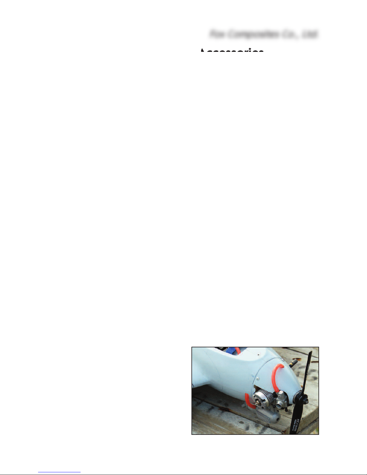
During testing of the 3 prototype models we ex-
perimented with the fitting of a small .15 glow
motor (Thunder Tigre .15), but the results were
rather disappointing ! It was much more work to
build, slightly heavier, noisy, dirty ... and did not
have the performance and ‘fun-factor’ of the elec-
tric versions. However we have included a couple
of photos of the glow motor installation, and a fi-
breglass fairing for the muffler is available as an
option, for anyone that wants to fit a small 2-
stroke motor.
Fox Composites Co., Ltd.
5

Building Instructions
The Komet is very quick and simple to build, but we recommend that you complete the fuselage
before the wings, as the front wing dowels and front wing joiner also hold the battery and R/C tray
into position in the fuselage - which means you need to complete this to fit your chosen Lipo flight
packs first.
Fuselage:
The lightweight fuselage is a fibreglass and epoxy moulding, with a vacuumed foam-sandwich
vertical fin, painted in the moulds in a single colour.
The 3 main bulkheads are made from a 6mm foam and glass sandwich, which is extremely light-
weight, and these are factory installed for you. Their purpose is to maintain the fuselage shape and
support the battery tray. We have also installed the balsa/fibreglass composite root ribs, the 3mm
balsa/fibreglass composite ring bulkhead in the nose area, and the 5mm thick fin bulkhead/spar.
Motor installation
The motor is secured to the fibreglass
ring mount supplied, with small bolts,
and the complete assembly is glued
into the nose cone, which is finally
glued onto the fuselage permanently.
Tip: You can wait to glue the nose
cone on until the rest of the fuselage
is finished, which gives easier access
when installing the battery tray, etc,.
It is important to set a little right-thrust
(about 2 degrees) into the motor
when gluing the mounting ring into
the nose. Therefore you must offset
the motor about 1.5mm to the (pilots)
left when bolting it into the fibreglass
ring - so that the propeller is still cen-
tred on the fuselage when installed.
Drill the fibreglass mounting ring to
suit the mounting holes of your motor
(1.5mm offset to the left), and cut out
the cooling slots for the motor also.
Bolt the motor to the mount, and
chamfer the outside edge a little to fit
the tapered shape of the nose cone.
Sand the inside surface of the fibre-
glass nose cone with 120 grit and
clean off the dust. Cut the circular
hole in the front of the nose cone for
cooling, which also allows you to ac-
cess the mounting bolts. This will
Fox Composites Co., Ltd.
6
(above) Typhoon 2W-20 bolted to the fibre lass motor
mount, with coolin slots cut out.
(below) Motor mount lued into nose cone, about
1.5mm offset to allow for the necessary ri ht-thrust.

need to be about 25mm (1”) diameter for the motors mentioned above.
We suggest that you tack glue the mount into the cone with 1 or 2 very small drops of CA, and then
temporarily tape the nose cone on the fuselage to confirm that it has the required side-thrust. No
down thrust is needed. Mark the position of the nose cone on the fuselage now, so that you glue
it back in the same position later, to
set the same thrust-line. When satis-
fied, remove the motor, and then glue
the motor mounting ring permanently
into the nose cone using a slow
(24hr) epoxy and micro-balloon mix-
ture. Finally glue the nose onto the
flange on the front of the fuselage,
using a little 30 minute epoxy.
Battery Tray
All the parts are supplied for the
balsa/fibreglass composite battery
and R/C tray, which is easily remov-
able for maintenance. It sits in the
cut-outs in the 3 foam bulkheads, and
is held into the fuselage by the front
anti-rotation dowels (which are glued
into the wings), and the front wing
joining rod.
If using the motor and battery packs
recommended, you will need to posi-
tion the middle of the battery approx.
over the front bulkhead (centred on
the front anti-rotation dowels) to
achieve the correct Centre of ravity.
The battery tray is carefully designed
to allow cooling air to circulate both
under and above the battery, which is
suspended in the hole in the tray on
the velcro straps. Adjust the size of
the milled hole (35 x 110mm) to suit
your Lipo flight battery, if necessary.
The battery should be a loose fit in
the hole.
The design also allows you to move
the battery forward or backwards
about 25mm (1”) after assembly, to fi-
nally set the exact C - and then you
can glue in some small balsa blocks
as ‘stops’ to retain it.
Fox Composites Co., Ltd.
7
(above) Completed battery tray, with the fibre lass
tube lued on the balsa blocks. The win joiner rod
slides thru’ tube to secure the tray in the fusela e.
(below) File rooves in the side-plates to take the Vel-
cro straps that secure the Lipo battery.
Fusela e bulkheads are factory-installed and shaped
to fit the supplied battery tray.

Insert the battery tray into
the fuselage, with the
front of it up against the
back of the balsa/glass
nose ring. (The end with
the small radius on the
corners goes at the back
- towards the Fin. Slide
the 2 short lengths of Ø
7mm rod (anti-rotation
dowels) thru’ the front
holes in each root rib, into
the 2 semi-circular
cutouts in the balsa side-
plates.
lue the 5mm balsa side-
plates onto the battery
tray so that your chosen Lipo fits between them, with at least 6mm (1/4”) space all around it for
cooling air flow. lue the 2 small blocks against the back of the side-plates, in line with the front
wing joining rod, and glue the fibreglass tube on top of them as shown, using the rod to maintain
alignment while the glue cures. Use 30 minute epoxy and micro-balloons mixture.
Note: If the tube will not fit on the joiner rod, then the clear plastic mold release sheet may still be
inside ! It can be pushed out easily with a round file.
The ‘standard’ sized 11.1volt (3S1P) battery pack shown is 25 x 25 105mm. You can also fit a pair
of 2S1P, or a 4S1P pack in the same position for increased performance and flight duration.
When the plane is completed, and the battery is finally located to set the C , then you need to file
slots as shown for the velcro straps that secure the battery in position for flight.
Cooling
Adequate cooling of the motor, ESC and Lipos
is extremely important to prevent damage to
these critical components, and the set-up
shown here has proved adequate - even in the
high ambient temperatures (32 - 36°Celsius)
of Thailand ! Remember that just by shutting
the motor ‘off’ for a few seconds in each circuit
allows the speed controller to cool down, and
the ESC works hardest, and gets hottest,
when using mid-throttle settings. The full-sized
Me-163 ‘Komet’ was a rocket-powered glider -
and the model also exhibits excellent gliding
characteristics.
If you will operate the Komet in warm ambient
temperatures (25°C and above), then we ad-
Fox Composites Co., Ltd.
8
(below) The battery tray is held into the fusela e by the anti-rota-
tion dowels and front win joiner, and very easy to remove.

vise that you make 2 triangular inlet
holes in the nose cone to provide
extra cooling of the motor & battery
pack. Don’t cut a cooling inlet hole in
the underside of the nose cone, as it
tends to ingest grass and dirt during
landing. If you fly in a much cooler
country than Thailand these holes
may be a little smaller than shown, or
possibly omitted altogether.
Cooling air flows under & above the
battery tray to provide the most effi-
cient cooling possible for the Lipos.
Do not use a spinner, as it may pre-
vent enough cooling air entering the
fuselage. Just use a simple prop-
adapter as shown here.
As a general rule, the Lipo batteries
should not get warmer then 55 de-
grees C, and the motor a maximum
of 70°. Most quality speed-controllers
will normally cut out if they get too
hot. If this happens in flight, and you
have enough height/speed, they will
usually work again after 10 - 15 sec-
onds of cooling, and this allows to
you make a circuit for landing. In this
case you know that you will need to
increase the cooling air inlet area be-
fore flying again.
Cockpit Canopy
Included in the kit is a very lightweight
fibreglass canopy, with the
foam/glass baseplate already in-
stalled. No clear cockpit canopy is
available for the Komet at this time.
The canopy is held in place with a
thin fibreglass, or plywood, strip glued
inside the back, which slides under-
neath the fuselage edge, and a hook
and rubber band at the front. lue the
strip in place with thick CA, leaving
about 5mm projecting as shown.
lue the milled 5mm balsa reinforce-
ments part onto the top of the foam
Fox Composites Co., Ltd.
9
5mm
The Cockpit canopy is secured with a fibre lass or thin
ply strip at the back, and hook and slot at the front,
with a rubber band to hold it ti htly in place for fli ht.
2mm
32mm
25mm

baseplate at the front, using epoxy
and micro-balloons, and file slot in
both for the 3mm thick liteply/glass
hook. The front of the hook that is
glued in should be about 32mm from
the front of the canopy. lue the hook
into the canopy, using 30 minute
epoxy and micro-balloons. Do NOT
use CA as it might melt the foam!
Leave a gap of about 2mm between
the hook and the foam base plate.
Cut and file a 3mm wide slot in the
fuselage to match the hook, with the
front of the slot approx. 25mm from
the front of the canopy position on the
fuselage. Adjust slot length for easy
canopy fitting.
lue a thin (approx. 0.5mm) plywood
shim inside the fuselage as shown
(cross-grain) to reinforce it, and also
to get a nice tight fit of the hook, using
epoxy. If the canopy is too loose on
the fuselage it rattles in flight !
1 or 2 small rubber bands over the
hook, and around the back wing
joiner rod, keep the canopy in place
by pulling it backwards and down-
wards. To remove the canopy you
only need to slide it forwards a little, until the fibreglass strip disengages from the fuselage, and
lift it up.
Rudder (optional)
As the Komet is usually hand, or
bungee, launched it is not necessary
to have a working rudder, unless you
want to fly knife-edge and point rolls
etc. However it does fly ‘rudder ma-
noeuvres’ very nicely indeed and it is
easy to fit if you wish, as we have
made provision for it during manufac-
ture.
There are 5mm thick balsa false trail-
ing and leading edges installed in the
Fin, and you only need to cut the rud-
der out with a razor saw, following the
moulded-in panel lines, and hinge it
using your favourite hinge type.
Fox Composites Co., Ltd.
10
A balsa fin spar and rudder leadin ed e are factory-
installed, in case you wish to fit a workin rudder. Cut
out the rudder, usin the moulded-in panel lines as a
uide, and hin e usin your favourite method.
(above) A very thin plywood shim is lued into the
fusela e to et a nice ti ht fit of the canopy hook.

You can easily check the exact position of
these by holding the fuselage up against a
strong light - and you will see the location.
The servo can be positioned on the side of
the fuselage, towards the rear of the cock-
pit, and a short straight pushrod connects
it directly to a small rudder horn with light-
weight plastic clevises. Add a fairing over
the linkage if you wish.
Main wheel (optional)
If you will land your Komet on a hard,
or abrasive, surface then you can in-
stall a single wheel in the front of the
‘keel’ of the fuselage to protect it.
A lightweight foam wheel of 38 -
45mm (1.5 - 1.75”) can easily be in-
stalled, but it is easiest if the wheel is
very narrow, approx. 10mm (3/8”)
wide. The current ‘factory’ model has
a single wheel fitted into the ‘keel’ of
the fuselage, centred about 25mm
back from the wing leading edge, and
this protects the fuselage when land-
ing on our short concrete runway.
2 small ‘skids’ under the wing tips, made from thin ply, plastic or fibreglass sheet, protect the un-
derside of the wings.
We made and tested several different types of ‘dolly’ for take-off from the ground, but the location
of the wheels was very critical to prevent ground-looping, and all made the model more complex
and were not really practical.
Fox Composites Co., Ltd.
11
(above) A li htwei ht wheel fitted in the fusela e pro-
tects it when landin on hard surfaces. 2 small patches
of 80 rit sandpaper lued on the fusela e helps to rip
it durin hand-launchin .

Wings:
The wings are laminated from a lightweight fibreglass and foam sandwich, cured under vacuum,
and are painted in the molds in a single colour. The elevons and servo hatches are elastic-hinged
and already cut out and trimmed for your convenience, at the factory.
The wings are held onto the fuselage with M4 x 20mm bolts (with washers), into T-nuts that are
installed in the wing root ribs during manufacture. You will need to use a short ball-ended allen
(hex) wrench to access these bolts, and they screw thru’ the composite root rib in the fuselage.
Note: These bolts are also on the C location !
Wing Joiners
The wings are joined using the two long Ø 7mm
fibreglass rods, slid thru’ the holes in the centre
and back of the wing roots, and these should not
be glued in place.
The middle wing joiner is the longest (300mm
length), and this should project out of both fuse-
lage roots a minimum of 65mm each side. The
rear joiner (240mm) should project at least 35mm
both sides. These joiners fit into fibreglass tubes
that are installed in the wings during manufacture.
The middle wing joiner also holds the battery tray
into the fuselage, passing thru’ the fibreglass tube
that is glued onto the tray. At the front of each
wing root there is a shorter fibreglass tube that
acts as an anti-rotation dowel, and at least 25mm
of these must be glued into each wing root (with
30 minute epoxy & micro-balloons), with just
enough length projecting to hold the side-plates
of the front of the battery tray in position. There-
fore, these cannot be glued into the wing until you
have built the battery tray to suit your Lipo.
Elevon Servos
The elevon servos are installed in the pre-cut,
elastic-hinged, hatches in the underside of the
wing, using the milled plywood mounts which are
sized to suit the JR DS-161 or Hitec HS-5125
‘thin’ digital wing servos. Adjust the plywood
mounts if necessary to fit your chosen servos ex-
actly, and screw them into place.
Set up an ‘Elevon’ mix in your transmitter, centre
the servos, fit the servo arms at 90° to the servo
case, and screw the servos onto the mounts.
Sand the top surface of the mounts, the inside of
the upper wing skins and back of the wing spars
in the servo pockets carefully for a good glue
bond. Do not glue them in place yet.
Fox Composites Co., Ltd.
12

Mark the position against
the outer edges of the
hatches where the servo
arms will be, and file
3mm wide x 20mm long
slots in the skin for them
as shown. Now you can
glue the mounts into the
wing, with the servos in
place, checking that the
servo arms are centred in
the slots, and parallel
with the wing roots. Use
a 30 minute epoxy and
micro-balloons mixture,
and make sure that they
are properly glued to the skin and to the back of
the wing spar in front of the servo pockets. When
the glue has cured, remove the servos and add
glue to any parts that are not properly bonded,
making sure that they are well fixed to the spar.
The linkages should be in line with the airflow
(parallel to the wing root), and in practice that is
close enough to the (ideal) 90 degrees to the
elevon hinge-line that it works fine. Tape the
elevons into the neutral position. Carefully mark
the line (on masking tape) of the linkage, exactly
in line with the servo arms. The control horns are
made from the 35mm lengths of M3 threaded rod,
and there are small plywood blocks installed in-
side the elevons for the horns during manufac-
ture. Drill right thru' the elevons on the marked line, exactly 10mm behind the leading edge, using
a sharp Ø 2.2 or 2.3mm drill. Use a 90° square to keep the drill perpendicular to the bottom sur-
face of the elevators. The holes should be just behind, or against, the balsa elevon L.E. spars.
Thread these holes, right thru' the elevons, using an M3 tap. Sand both ends of the threaded rods
flat, and screw on the plastic adapters provided. Screw them into the tapped holes until the upper
end is flush with the top outer surface of the elevons. The M3 rods are finally secured in place by
applying glue through the open (root) end of the elevons. Apply one drop of thick CA and, when
cured, add a little 30 minute epoxy and micro-balloons mixture.
Make up the linkages using M2 or 2 x 56 clevises and threaded rods. The clevises will need to be
in the servo horn hole approx. 13mm from the servo centre, and the clevise on the elevon horn as
far out as possible - to maximise the mechanical advantage, whilst still obtaining the necessary
maximum elevator throws of 10mm ‘up’. The servo hatches can be held closed with strips of clear
tape. Some small scraps of very thin ply or fibreglass sheet glued inside the corners of the servo
pockets keep the hatches flush with the wing skin.
IMPORTANT: Do NOT use ball-joints or ball-links on the plastic horn adapters, or plastic servo
arms. They will cause twisting, and almost certain flutter !
Fox Composites Co., Ltd.
13
(above) Completed elevon servo installa-
tion, elevon horn and linka e.
(below) Elastic hin ed servo hatches are se-
cured with clear tape for fli ht.

Gear Installation:
Actually there is not
much gear to install ! The
milled balsa/fibreglass
battery tray is easily re-
movable when the wing
joining rods are slid out,
so you can do the final
battery and gear installa-
tion on the workbench -
rather then trying to work
inside the small fuselage.
Of course the speed-con-
troller should be fitted as
close to the motor as
possible, and you should
not extend the wires on it
- or on the motor. We
mounted it on the side of
the fuselage, in the air-
flow above the battery,
using double-sided self-
adhesive velcro pads.
We recommend that you
use a speed-controller
with a BEC cir-
cuit, so there is
no separate Rx
battery needed,
and therefore
also no switch.
Fit the Receiver
as far away as
possible from
the ESC and
motor, for the
least chance of
interference.
We fitted it on
the back of the
battery tray as shown, also with velcro pads, and in this case a 2.4 Hz system was used, which
certainly seems to give a much better ‘range check’ and a more ‘locked-in’ feeling than the 35 and
72 MHz RX’s we used in the first prototype. The other advantage is that you don’t have the long
antenna wire hanging out of the back of the fuselage....
Fox Composites Co., Ltd.
14
(above) Battery and 2.4 GHz Receiver installation in the ori inal
prototype Komet. ESC is fixed to upper ri ht fusela e, above the
front of the Lipo, with double-sided velcro.
(below) Installation in the first ‘production’ kit. Kokam 3200 4S
Lipos, Phoenix 60 amp ESC, Typhoon 2W-20 motor, Graupner 4.7
x 4.7” prop, 2.4 GHz Rx. In excess of 130mph from shallow dive.
* Complete system packa es are available from ‘Overlander’.

Finishing:
The ‘Komet’ kit is supplied painted in the molds - either all-grey or all-red. The paint used is a 2-
pack polyurethane, which will accept most other types of paint on top of it without any problems.
However, if you plan to add paint trim please test your chosen paint on a small 'hidden' area that
will not be seen to check compatibility! If you want to paint some parts, or add markings/decals,
please make sure that you have cleaned the paint surface very well to remove all traces of wax
or mold release agent first. You can use de-natured alcohol or cigarette lighter fluid for this with-
out any risk of damaging the existing painted surface. We also suggest that you lightly sand any
surfaces to be painted with 800 grit wet-and-dry (used wet) to prepare the surface.
R/C set-up and Flying:
Centre of Gravity
Set the Centre of ravity at 91 -
93mm back from the L.E. joint of the
wings to the fuselage. This is exactly
on the position of the wing bolts, and
can easily be checked by hanging the
completed model on 2 lengths of thin
string from the bolts, with the wings
pulled slightly away from the fuse-
lage, as shown here.
Don’t forget to check the lateral C
and, if necessary, add a small weight
in the lightest wing tip.
Thrust Line
It is important to set about 2 degrees
right thrust into the motor, as ex-
plained in the motor installation sec-
tion. No up or down thrust is needed.
Control Surface Throws
We strongly recommend that you
should don’t exceed the throws men-
tioned here for the 1st flights, as the
elevons are quite powerful because
of the short tail-moment.
Throws are measured at the widest
(root) end of each elevon.
It is not really necessary to use dual
rates if you set some exponential into
the elevons (both ailerons & eleva-
tors), but please read Jim’s “Flying
Fox Composites Co., Ltd.
15
(above) For correct Centre of Gravity the Komet should
han level on 2 strin s suspended on the win bolts.
(below) Set approx. 2 de rees ri ht side-thrust into the
motor mount when luin it into the nose cone.
approx. 2°
ri ht-thrust

Notes”, below, for more information - as it is useful to have higher ‘up’ elevator throws for landing.
Ailerons: 5mm ‘up’ and 5mm ‘down’. Set 40% exponential in the ailerons.
Ele ators: Low rate/normal flying : 8mm ‘up’ and 7mm ‘down’.
Optional High rate (for landing) : 10mm ‘up’.
We also recommend at least 40% exponential on the elevators.
Rudder (optional): 10 mm ‘left’ and ‘right.
Flying the ‘Ko et’
It’s always a good idea to have an experienced pilot friend standing by your side for the first flight.
He can act as your timer, advise you when to land, and watch for other traffic in the circuit or haz-
ards on the runway during landing - generally reducing your workload.
I have had a lot of fun flying the Komet but you need to be ‘on the ball’ ! Take off from a hand-launch
is no problem but it needs a good straight throw, just aimed up a few degrees, especially if there
is no wind. You will need to hold in some ‘up’ elevator during the initial stage and then relax it as
the speed builds up.
It is a good idea to glue a couple of small patches of 80 grit sandpaper on the outside of the fuse-
lage, as shown below, so that you can ‘grip’ the rather wide, smooth, fibreglass fuselage for hand-
launching. If using a powerful motor set-up, you may find that launching is easier on about 75%
throttle, as the plane has a tendency to pull ‘downwards’ out of your hand on full power.
The Komet does not seem to lose speed during turns so be prepared to throttle back after half a
circuit or so, until you have got it fully trimmed. All rolling and looping manoeuvres are normal,
with rolls being especially nice to do, and very axial. Outside loops are OK but need a little more
room, so start these with plenty of height for the first few. If you fit a rudder then you will find then
Komet very neutral with regards to aileron coupling. In other words it does not roll when the rud-
der is applied. reat for point-rolls and knife-edge !
We flew our first prototype on a 400 watt Mega motor for the first flights and performance was
very good, and this will be adequate for most pilots. I then built one with a .15 size glow motor and
was fairly disappointed, although it seemed to slow up better for landing than with the much cleaner
electric nose set up.
We later fitted a 700 watt Typhoon motor, and this gives startling performance on 3 cells although
we have to be a little careful of battery temperature when using this set-up in Thailand. Battery tem-
perature is a big problem here in Thailand as it is always at least 30+ degrees Celsius, but my
friend reports no problems when flying in the UK. (Check the cooling section in these instructions
for more info)
We then tried it on 4 cells, and it had even better performance. It was ‘radar checked’ at over 150
mph (240kph) on a no-wind day, in cool conditions in England. This was after a steep dive, with
132mph being achieved on 3 cells. The elevator gets more sensitive at this kind of speed and you
must be careful that you do not overstress the airframe by using too much movement. I use around
40 per cent exponential, but you must make sure you understand it and get the softer part of the
elevator movement in the centre. Stick to the recommended throws shown above.
The Komet glides very well but is still quite fast. It will loop and roll on the glide if you keep the
Fox Composites Co., Ltd.
16

speed up. Landings are fairly fast and for the first one or two I would make sure you have some
battery power left for a ‘go-around’ in case you overshoot.
The Komet is quite docile when gliding and you can slow it down and apply full ‘up’ elevator with
no vices, other than it slows and stops - so again, check the ‘stall’ characteristics at height until you
are familiar with it’s flying qualities, as you lose elevator control when the speed decays. This is
why I use a high-rate elevator for landing only.
I hope you enjoy flying your Komet as much as I do. It reminds me of my Club 20 pylon racing days.
I am sure you could fit many other makes and types of motor, but the ones we have mentioned
here are a guide.
Have fun !
Jim.
Kit Contents
1 Fuselage (with 5 bulkheads installed)
1 Nose Cone
1 Cockpit canopy (with foam baseplate installed)
1 Wing panel, Left (T-nut installed)
1 Wing panel, Right (T-nut installed)
1 Small parts bag.
1 CD-Rom for ‘Komet’, with Instructions .pdf file and photos
1 Packing Checklist.
Fox Composites Co., Ltd.
17
(above) The 1st ‘production’
Komet, painted in a camou-
fla e scheme, has been
tested extensively in the UK
to evaluate different power
packa es and airframe in-
te rity.
(left) Jim Fox with the low-
motor powered prototype
‘Komet’, after another suc-
cessful test-fli ht.

S all Parts Bag
1Battery tray (3mm balsa/glass)
2 Side rails for battery tray (5mm balsa, milled)
2Blocks for battery tray, 15 x 10 x 10mm (balsa)
2 Wing servo mounts (6mm composite lite-ply)
1 Motor mount ring Ø 35mm (fibreglass)
1 Canopy Hook (3mm composite lite-ply)
1 Reinforcement for canopy hook (5mm balsa)
1 Fibreglass Strip, 10 x 70mm (canopy rear fixing)
1 Fibreglass Wing joiner, Ø 7mm x 300mm (front wing joiner)
1 Fibreglass Wing joiner, Ø 7mm x 240mm (back wing joiner)
2 Fibreglass rod, Ø 7mm x 85mm (anti-rotation dowels)
1 Fibreglass tube, I.D. 7 x 70mm (to secure battery tray)
2 Allen bolt, M4 x 20mm (wing fixing bolts)
2 Washers for M4 bolts (for above)
2 M3 x 35mm threaded rod (for control horns)
2 Plastic Adapters, M3 (for control horns)
Acknowledge ents/Credits:
Fox Composites would like to thank Overlander Technologies for their assistance and advice with
regard to the power system for the ‘Komet’, and Brian Teasdale for permission to use some of his
excellent photos of the 1st production plane in this Manual.
Fox Composites Co., Ltd.
18
Compiled by Mike Cherry (18 February 2008)
Mac
Milled wood, hardware & s all parts included in the kit.
Table of contents
Other Fox Composites Toy manuals
Popular Toy manuals by other brands

Mattel
Mattel Barbie M8969 instructions

GREAT PLANES
GREAT PLANES Yak-55M Performance Series instruction manual

Eduard
Eduard BRASSIN F-4 exhaust nozzles USAF early manual

Mattel
Mattel Disney PIXAR TOY STORY 4 BLAST-OFF BUZZ... instructions

LEGO
LEGO 75911 SPEED Champions Assembly guide

ProJet
ProJet Nitro-O03 instruction manual