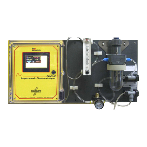
Foxcroft FX-1000p User manual

Foxcroft Equipment & Service, Co. Inc.
Model FX-1000p
Amperometric Chlorine Residual Analyzer
Instruction Manual
The FX-1000p Amperometric Chlorine Analyzer includes an instruction manual that contains important
information about its operation. Purchasers who install this analyzer for use by others must leave this
instruction manual or a copy with the user.
Copyright © 2012 FOXCROFT
Every effort has been made to ensure the accuracy of this document at the time of printing. In accordance with the
company’s policy of continuous product improvement, Foxcroft reserves the right to make product changes without notice.
No liability is accepted for any consequential losses, injury or damage resulting from the use of this document or from any
omissions or errors herein.
Warning!
Please Read Carefully and Save.

Table of Contents
2
Important Safety Information 4
Introduction 5
Specications 7
1 INSTALLATION 8
1.1 Unpacking 8
1.2 Mechanical Requirements 8
1.3 Sample Point Selection Guidelines 10
1.4 Sample Line 10
1.5 Sample Flow 10
1.6 PLUMBING 11
1.7 ELECTRICAL 14
2 STARTUP 21
2.1 Buffer Feed Pump Tube Selection 21
2.2 Preparing Buffer Solution 22
2.2 Preparing Copper Electrode 24
2.3 Preparing System for Calibration 25
3 CALIBRATION 26
3.1 Setting Zero Control 26
3.2 Setting Standard. Control 26
3.3 Coarse Adjustment 27
4 SPECIAL CONFIGURATIONS 29
4.1 Trimmer Locations 29
4.2 Setting Alarm Relays 30
4.3 Changing Measuring Range 31
4.4 4-20mA Output Adjustment 34

3
5 MAINTENANCE 35
5.1 Preserving Measurement Accuracy 35
5.2 Maintenance Schedule 35
5.3 Cleaning the Copper Electrode 36
5.4 Peristaltic Pump Motor Replacement 38
5.5 Mixer Gap Adjustment 40
5.6 PREVENTIVE MAINTENANCE KIT 41
6. AUXILIARY KI PUMP 46
6.1 Total Chlorine 46
6.2 Installation of Auxiliary KI Pump 46
7PARTSLISTING 48
7.1 Electronics 48
7.2 Amperometric Cell 49
7.3 Cell and Pump Parts 50
8 ACCESSORIES 51
9 TROUBLESHOOTING 52
10 SERVICE 56
10.1 System Repair 56
11 PRODUCT WARRANTY 60
Table of Contents

IMPORTANT SAFETY INFORMATION
Opening the analyzer door exposes you to line voltage, if present, at power terminals TB-1D at the
bottom of the enclosure. This may be hazardous. Always remove power source before entering this
area of the enclosure. However, the display board contains only low voltage and is completely safe to
handle.
Wiring or repairs should only be performed by qualied personnel and only to an unpowered analyzer.
Whenever it appears that system safety is questionable, disable the system to ensure against any
unintended operation. For example, an unsafe condition is likely when:
1. The system appears visibly damaged.
2. The system fails to operate properly or provide the intended measurements.
3. The system has been stored for long periods at temperatures above 120ºF (49ºC).
This measurement system must be installed by specially trained personnel in accordance with relevant
local codes and instructions contained in this instruction manual. Observe all technical specications
of the system. If one line of the power source is neutral, use a double-pole main switch to disconnect
the analyzer.
HELPFUL IDENTIFIERS
In addition to information on installation and operation, this instruction manual may contain WARNINGS
pertaining to user safety, CAUTIONS regarding possible instrument malfunction, and NOTES on
important, useful operating guidelines.
Please read and observe the following:
WARNING: A warning looks like this. It warns you of the potential for personal
injury
CAUTION: A caution looks like this. It alerts you to the possibility of instrument
malfunction or damage.
NOTE: A note looks like this. It alerts you to important operating information.
4

5
Introduction
General Information
Instrument Description and Capability
The FX-1000p Amperometric Chlorine Residual Analyzer amperometrically measures the free or total
residual chlorine in treated drinking water, process water, or wastewater using integral gold and copper
bare electrodes that are not covered by a membrane.
Amperometric measurement means that the chlorine residual reading is determined by measuring
the electronic amperage of the measuring cell. The amperage level is directly proportional to the
level of free chlorine available as hypochlorous acid in the sample stream. In the case of reading total
chlorine, the unit is actually reading converted free iodine from the potassium iodide that is added to
the cell for total chlorine readings.
The required continuous sample ow is brought to the analyzer from an existing pressurized line or
can be pumped from a well or reservoir. The sample ows by gravity through the ow/measuring cell
and discharges to waste after measurement.
A peristaltic pump continuously injects a precise amount of 5% food grade distilled white vinegar into
the sample to lower the pH in the measuring cell to 4-5 pH.
The system provides a 4-20mA analog output that is scaled to the factory set measuring range. This
output can be used to drive a residual chlorine control system using compound-loop or set point
controllers; or input to a chart recorder, telephone dialer, data logger, or SCADA system.
These important factors enable the FX-1000p to provide drift-free measurements:
1. Buffer solution feed rate is constant.
2. Flow rate to sample ow cell is kept constant.
3. Large surface area made with pure grades of gold and copper are used to measure the residual
chlorine.
4. The sample ow cell has a reliable cleaning method to keep the electrodes free of dirt, ensuring
measurement accuracy. The distilled white vinegar buffer solution, mixing balls, and process
chlorine act together to keep the ow cell clean.

Buffer Pump
Measurement Cell
Electronics Enclosure
Figure 1
Figure 2
Introduction
6
FX-1000p

Specications
Operational
Type of Measurement Amperometric (free or total chlorine)
Measurement Range 0-5.00 ppm (mg/l) factory-set range; other eld-congurable
measuring ranges are: 0-0.50; 0-1.00; 0-2.00; 0-3.00; 0-10.0; 0-20.0;
0-0.50; and 0-60.0 ppm (mg/l)
Display Three-digit LED; 0.56 in. (14 mm) high
Ambient Conditions 32-120°F (0-49°C); 0-95% relative humidity, non-condensing
Analog Output One isolated 4-20mA (600 ohms max. load)
Relays Two electromechanical relays (high and low alarms); SPDT (form C)
contacts; rated 1A @ 120 VAC
Power Requirements 100-130 VAC, 50/60 Hz (30 watts); optional 200-240 VAC, 50/60 Hz
Performance
Sensitivity 0.001 ppm (mg/l)
Accuracy +/- 0.25% of full scale
Repeatability 0.004 ppm (mg/l) or 1% of full scale, whichever is greater
Stability +/- 1% of full scale per month
Response Time 4 seconds from sample entry to display indication
Full Scale Response 1.5 to 2.0 minutes
Sampling
Sample Temperature Range 32-120°F (0-49°C)
Sample Flow Rate 150-1000ml/min. (500 ml/min. recommended)
Sample Cell Use 120 ml/min xed
Sample Supply Continuous. Where sample ow is interrupted, provisions must be
made to keep the electrodes wet.
Sample pH Range 3.0-10.0 pH
Sample Alkalinity Range 0.05-350 ppm (mg/l) total
Sample Turbidity Limit Less than 250 NTU
Electrode Materials Cathode (measuring): Gold (24K, 99.95%)
Anode (reference): Copper (99.9%)
Buffer Requirements:
Free Chlorine
Total Chlorine
White distilled vinegar (5% food grade)
White distilled vinegar (5% food grade) mixed with prescribed
amount of potassium iodide (KI)
Mechanical
Enclosure NEMA 4X; berglass; surface mount
System Net Weight 14.8 lbs. (6.7 kg) approximately
Sample Inlet Line 1/4” id x 3/8 od x 3’ length, clear exible PVC tubing
Buffer Feed Line Tubing #14 neoprene tubing (factory-installed)
#13 neoprene tubing x 9” (supplied)
Drain Lines 5/8” id x 3/4” od x 3’ length, clear exible PVC tubing (2)
7

After unpacking, it is recommended to save the shipping carton and packing materials if
the instrument must be stored or re-shipped. Inspect the equipment and packing materials
for signs of shipping damage. If there is any evidence of damage, notify the transit carrier
immediately.
The shipping container consists of the following:
1 FX-1000p Amperometric Chlorine Analyzer
1 Buffer Bottle Bracket
1 Sample Tubing 1/4” id x 3/8” od x 3’ length, clear exible PVC tubing
1 Sample Drain Hose 5/8” id x 3/4” od x 3’ length, clear exible PVC tubing
1 Overow Drain Hose 5/8” id x 3/4” od x 3’ length, clear exible PVC tubing
2 Buffer Pump Tubing #13 neoprene tubing x 9”
1 Set of Four Mounting Feet with Four Screws
1 Instruction Manual
Serial Number
The FX-1000p Amperometric Chlorine Analyzer measurement system has two serial number labels
found on the bottom right side of the enclosure, and on the top of the base plate inside the enclosure.
The label on the outside of the enclosure indicates the chlorine residual range. Should technical
assistance be required, refer to the serial number to identify your system.
Mechanical Requirements
Location
Mount the FX-1000p Amperometric Chlorine Analyzer in a location that is:
• Out of direct sunlight
• Protected from the elements (rain, snow, ice, dust, etc.)
• As close to the sample point as possible to minimize sample lag time
• Accessible
• Clean and dry where there is little or no vibration
• Protected from corrosive uids
• Within ambient temperature limits (32-120°F, 0-49°C)
Important: Mounting the system in direct sunlight may increase the ambient temperature above the
maximum specied limit.
Mounting
1. Attach the four mounting feet to the rear of the electronics enclosure using the included at head
screws.
2. Orient the analyzer so that the sample ow cell drain outlets are pointing downward.
3. Anchor securely to a wall at approximate shoulder height for convenience.
Installation
8

The FX-1000p should be level from side to side and front to back to ensure that its integral weir
operates properly.
4. Attach the vinegar bottle bracket on the wall. The bottom of the bracket should be about 3” above
the bottom surface of the electronics enclosure, and slightly below the height of the peristaltic
pump mechanism.
Do not mount the vinegar bottle higher than the peristaltic pump mechanism. This could lead
to atmospheric siphoning of the buffer which can occur if the pump occlusion ring is loose, the
pump bearings are worn, or if the tubing has a at spot from wear.
Wall Mounting Enclosure Mounting
Not Recommended Better Arrangement
Best Arrangement
Figure 3 Figure 4
Figure 5 Figure 6
Figure 7
Installation
9
FX-1000p

Sample Point Selection Guidelines
The sample must be taken at a point after the chlorine has been thoroughly mixed and has had time
to react completely with the process water. The sample line should be run with 3/8” diameter tubing to
minimize lag time between the process water and analyzer.
The sample point should always be located as close to the analyzer as possible so that the residual
chlorine in the water sample at that point is essentially the same as that in the analyzer ow cell.
A sample point that is too close to the chorine injection will deliver a sample that is not mixed adequately
or has not had sufcient time to complete the chemical reaction, thereby producing inaccurate readings.
Sample Line
When installing the sample line into the larger process pipe, use corrosion resistant brass or plastic
ttings only. The sample tap should be installed into the center of the pipe from either the top or side to
minimize chance of introducing air bubbles or sediment into the analyzer.
A sample valve upstream of the sample ow cell inlet tubing is required. We suggest using a metering
ball valve, needle valve or globe valve. If pressure exceeds 15 PSI, a pressure reducing valve is
required.
Sample Flow
Ensure that the water sample line is capable of delivering a continuous ow between 150 and 1000 ml
per minute to the sample valve at approximately 15 psi. If pressure exceeds 50 psi, use an auxiliary
water pressure reducing valve. If necessary, due to a long tubing run, increase the ow to the sample
ow cell to reduce the water sample transport time.
Consistent ow is critical to accurate measurement. A change in ow rate during operation of a calibrated
analyzer will require a recalibration of the analyzer. It is preferred to install a pressure regulator and
ow control valve to ensure a consistent ow. The part number FX-1000p-RM is available to control
the sample ow and pressure into the analyzer.
Dirty water applications require a ushing wye strainer to remove particulates from the sample.
Installation
10
FX-1000p

Plumbing Connection To The Analyzer
Connect the supplied 1/4” id x 3/8” od x 3’ length, clear exible PVC sample line to the ow control
valve and secure. Cut if necessary to keep the sample line as short as possible. Route the tubing
down to the analyzer, through the sample line guide hole and into the ow cell. Insert the end of the
tube about half way down from the top edge of the center drain cup in the ow cell.
Connect the two supplied 5/8” id x 3/4” od x 3’ length, clear exible PVC drain lines to the overow
drain on the right side of the ow cell block and to the measuring cell drain on the left side. Route the
hoses down to maintain gravity feed into a drain.
Buffer feed tubing is connected at the factory to the buffer input tting located on the inner side of the
lower block of the ow cell and to the blue bottle cap. Route the clear 1/8” od tubing to the vinegar
bottle with the original bottle cap removed. Insert the tube with sinker attached to the bottom of the
vinegar bottle and secure the cap.
Typical Plumbing
Installation (Plumbing)
Sample Drain
Overow Drain
Figure 8
Figure 9
Typical Plumbing
11

Clean Water Application Dirty Water Application
Figure 10
Figure 11
Installation (Plumbing)
Reservoir Application
Figure 12
12
FX-1000p

Carbon Filter Installation
Figure 14
Non-Continuous Flow Application
Figure 13
Installation (Plumbing)
13
FX-1000p

Conduit Holes
Run all wiring in 1/2-inch, grounded metal conduit. If using only shielded cable,
appropriate strain reliefs or cable grips are required. Seal unused cable entry holes with appropriate
plugs.
NOTE: Use NEMA 4-rated ttings and plugs to maintain the watertight integrity of the NEMA 4X
enclosure.
Important: The electronics enclosure is not a junction box and should not have any other wiring
running through it.
Important: This non-metallic enclosure does not automatically provide grounding between the conduit
connections. Grounding must be provided as part of the installation.
Electrical Connections
Make electrical connections to terminal strips located on the bottom circuit board in the enclosure.
To access this board, unfasten the thumb nuts on the four threaded standoffs, and carefully remove
the cover plate and top display/controls circuit board. Make sure that the ribbon interconnect cable
remains securely attached at both ends. If you prefer to remove the top circuit board and disconnect
the ribbon interconnect cable to make power connections, do so with extreme care to prevent bending
the ribbon interconnect cable connector pins.
Installation (Electrical)
Cover Plate
Conduit Connections
Figure 15
14

AC Power
TB-1D AC power input terminal is shown below. Use maximum 14 gauge stranded wire only. Do not
use solid wire. Always connect to an earth ground.
Analog Output 4-20mA
The isolated 4-20mA output signal is provided at terminals on TB-1E. This output can drive a load of
up to 600 ohms. Connect the load device, matching polarity as indicated.
NOTE: Do not run line voltage and low level signal voltage in the same conduit.
110/220 VAC INPUT
4-20MA Analog Output
Figure 16
Figure 17
Installation (Electrical)
15
FX-1000p

High and Low Alarm Relay Outputs:
The FX-1000p is equipped with two electromechanical relays. Two sets of SPDT relay outputs, one
for high alarm and one for low alarm. They energize upon alarm conditions and are located on the
bottom circuit board.
The relay outputs are not powered. The line power used to power the system may also be used to
power the alarm or control devices with these relay contacts. Always check control wiring to ensure
that line power will not be shorted by the relay switching action, and that wiring conforms to local
codes.
Important: Do Not Overload Relays. 1 amp Maximum, @ 125 VAC. Circuit Board damage will occur
if relays are overloaded.
Output Relays
Figure 18
Figure 19
Installation (Electrical)
16
FX-1000p

Connecting External Devices
Connecting a Chart Recorder:
4-20 mA Signal
Recorder must be congured for 4-20mA
input signal. See Model FX-4300
instruction manual.
Figure 20
Electrical Schematic
Figure 21
Installation (Electrical)
17
FX-1000p

Connecting a Telephone Dialer:
High Alarm Status Signal
Figure 23
Electrical Schematic
Installation (Electrical)
Low Alarm Status Signal
Figure 22
See Model FX-1104 or Model FX-1108
instruction manuals.
18
FX-1000p

Connecting a Metering Pump:
+ 4-20 mA signal -
- 4-20 mA signal +- 4-20 mA signal +
4-20 mA Out
FX-8500 Single
Loop Controller
Metering Pump
Figure 24
Electrical Schematic
Figure 25
Installation (Electrical)
19
FX-1000p

Connecting a Compound Loop Control System:
+ 4-20 mA signal -
- 4-20 mA signal +- 4-20 mA signal +
4-20 mA Signal
Chlorine Control
Valve
FX-8500 Compound Loop
Figure 26
Flow Meter
Electrical Schematic
Figure 27
Installation (Electrical)
20
FX-1000p
Table of contents
Other Foxcroft Measuring Instrument manuals