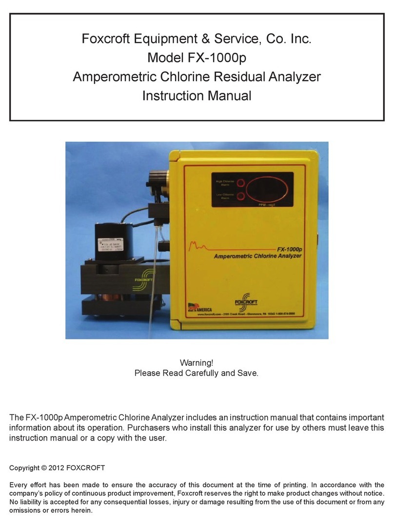
Foxcroft FX-CL-F User manual

Document No. OMFXCLFT042018.1
2018 Foxcroft Equipment & ervice Co. Inc.
Model FX-CL-F/T
Reagentless Amperometric
Free or Total Chlorine
Residual Analyzer
Instruction Manual

2

3
Table of Contents
Section1 General Information 5
1.1 Safety Information 5
1.2 Precautionary Labels 5
1.3 System Description, Limitations
6
1.4 Sensor Precautions 7
1. Total Chlorine Sensor Description & Operation 8
1.6 3-Electrode Free Chlorine Sensor Description & Operation 9
1.7 2-Electrode Free Chlorine Sensor Description & Operation 10
1.8 Assembly Diagram, 3-Electrode Sensors 11
1.9 Assembly Diagram, 2-Electrode Sensor 12
1.10 Specifications, Total Chlorine Sensor 13
1.11 Specifications, Free Chlorine Sensors 14
1.12 Flow Cell Assembly
15
1.13 Sensor & Flow Cell Assembly 16
Section 2 Sensor Preparation, Assembly, Maintenance
2.0 Membrane Cap Removal, Filling With Electrolyte
17
2.1 Assemble the Sensor 19
2.2 Sensor Installation 20
2.3 Sensor Conditioning 21
2.4 Cleaning The Electrode Finger Tip 22
2. Sensor Maintenance, Storage 23
Section 3 System Component Identification & Description
3.0 Model FX-CL-F/T Specifications 24
3.1 Analyzer Component Identification & Description 25
3.2 Main Circuit Board Component Identification
26
Section 4 Installation
4.1 Sample Point Selection Guidelines 27
4.2 Unpacking 28
4.3
Serial Number & Software Version
28
4.4 Locating the Analyzer 28
4. Wall mounting, plumbing 29
Section
Electrical Installation
.1 Electrostatic Warning 30
.2 Power Connection 30
.3 Circuit Board Layout and Identification
31
.4 Factory Default Wiring 32
.41 Chlorine Sensor Input 32
.42
Display wiring
32
.43 Power Input 32
.44 Current Output Wiring 33
.4 RS48 Serial Output Wiring 33
.46 Wiring Form C 1A Relays 33
Section 6 Startup 34
Section 7 Touch Screen Interface & Navigation 36
7.1 Main Screen Identification and Description 36
7.2 Menu Structure 37
7
.3 Screen Navigation
3
8
7.4 Configuring the Operating Range & mA Output 39

4
Table of Contents
7
.6 Configuring the Alarm Relays
40
7.7 Calibration 40
7.71 Setting the Zero Point
42
7.72 Calibrating the Span (Standard) 42
7.81 Settings Submenu Screen 43
7.82 Screen Settings 43
Section 8 Troubleshooting 44
8.1 Specific Troubleshooting Of The Sensor 45
8.11Testing the leak-tightness of the membrane cap 45
8.12 Testing the sensor electronics (dry run) 46
8.13 Testing the zero point 46
Section 9 Maintenance
47
Section 10 Parts List 48
Section 11 Service Contact, Return Policy 49
Section
12
Product Warranty
50

Section1
General Information
Every effort has been made to ensure the
accordance with the company’s policy of continuous product improvement, Foxcroft reserves the right
to make product changes and changes in this manual at any time without notice or obligation.
No liabil
ity is accepted for any direct, indirect, special, incidental or consequential damages resulting
from any defect or omission in this manual.
Document No. OMFXCLF
T04201
1.1 Safety Information
CAUTION:
You must read and follow the sensor
analyzer to prevent damage to the sensor.
Please read this entire manual before unpacking, setting up, or operating this equipment.
Pay attention to all danger and caution statements. Failure to do so
the
operator or damage to the equipment.
Do not use or install this equipment in any manner other than that specified in this manual.
Be certain the unit is disconnected from the power source before attempting to servi
component.
HELPFUL IDENTIFIERS
In addition to information on installation and operation, this instruction manual contains WARNING
pertaining to user safety, CAUTION regarding possible instrument malfunction, and NOTE on
important usef
ul operating guidelines.
1.2 Precautionary Labels
This symbol indicates a device sensitive to Electro
that care must be taken to prevent damage to the device
WARNING
This symbol and word indicates that possible
precautionary measures are not carried out
CAUTION
Alerts you to the possibility of instrument damage or malfunction
NOTE
Alerts you to important operating information
General Information
Every effort has been made to ensure the
accuracy of this document at the time of printing. In
accordance with the company’s policy of continuous product improvement, Foxcroft reserves the right
to make product changes and changes in this manual at any time without notice or obligation.
ity is accepted for any direct, indirect, special, incidental or consequential damages resulting
from any defect or omission in this manual.
T04201
8.1
You must read and follow the sensor
precautions before attempting to start up the
analyzer to prevent damage to the sensor.
Please read this entire manual before unpacking, setting up, or operating this equipment.
Pay attention to all danger and caution statements. Failure to do so
could result in serious injury to
operator or damage to the equipment.
Do not use or install this equipment in any manner other than that specified in this manual.
Be certain the unit is disconnected from the power source before attempting to servi
In addition to information on installation and operation, this instruction manual contains WARNING
pertaining to user safety, CAUTION regarding possible instrument malfunction, and NOTE on
ul operating guidelines.
This symbol indicates a device sensitive to Electro
-
tatic Discharge and indicates
that care must be taken to prevent damage to the device
This symbol and word indicates that possible
personal injury may occur if the
precautionary measures are not carried out
Alerts you to the possibility of instrument damage or malfunction
Alerts you to important operating information
accuracy of this document at the time of printing. In
accordance with the company’s policy of continuous product improvement, Foxcroft reserves the right
to make product changes and changes in this manual at any time without notice or obligation.
ity is accepted for any direct, indirect, special, incidental or consequential damages resulting
precautions before attempting to start up the
Please read this entire manual before unpacking, setting up, or operating this equipment.
could result in serious injury to
Do not use or install this equipment in any manner other than that specified in this manual.
Be certain the unit is disconnected from the power source before attempting to servi
ce or remove any
In addition to information on installation and operation, this instruction manual contains WARNING
pertaining to user safety, CAUTION regarding possible instrument malfunction, and NOTE on
tatic Discharge and indicates
personal injury may occur if the
Alerts you to the possibility of instrument damage or malfunction

6
Section 1.3 System Description, Limitations
You must read and follow the sensor precautions before attempting to start up the analyzer to
prevent damage to the sensor.
The Foxcroft model FX-CL-F and FX-CL-T both use a membrane covered amperometric sensor to
continuously monitor and control free or total residual chlorine without any reagents or moving parts.
The difference between the two models is the type of sensor used and corresponding measurement it
produces, free or total chlorine. The analyzer interface is the same for both sensor types except for
the available operating ranges for each sensor type.
The measurement system does not alter the sample and does not add chemicals to the sample
stream.
The model FX-CL-F/T is intended to sample process water that has been treated to US EPA
National Secondary rinking Water Standards or swimming pool quality standards only.
Wastewater that has undergone tertiary treatment may be possible to monitor if final water product is
at or near drinking water standards.
For the measuring methods used here, chlorine diffuses through the membrane from the
measurement medium and, combined with the electrolytes, triggers an electrical signal at the working
electrode. This signal is proportional to the concentration of chlorine and is amplified by the
electronics. The measurement signal is independent of the temperature of the media due to an
integrated temperature compensation.
pH has an effect on chlorine measurement accuracy since the sensor measures only the
hypochlorous acid (HOCl) form of chlorine, and not the hypochlorite ion (OCl
-
) form of chlorine. The
ratio of these two different types of chlorine varies with the pH value of the analyte. This behavior is
described by the hypochlorous acid dissociation curve. In the 3-electrode sensor there is a linear loss
of slope, or decrease in residual value, of about 5% for every 1 pH unit increase after pH 7. In the 2-
electrode sensor there is a 65% loss of slope at pH 8.
The sensor is not intended or recommended to measure or ensure the absence of chlorine.
The sensor is not suitable for determining organic chlorination agents such as cyanuric acid based
products.
The sensor cannot distinguish between various species of chloramines.
The analyzer requires a constant and consistent sample flow at no more than atmospheric pressure
as well as a waste drain.
The monitoring of reservoirs, basins or tanks requires a pump to deliver sample to the analyzer at the
required pressure and flow rate. Intermittent operation is possible within certain time limitations.
Residual measurements are determined and output continuously, the analyzer does not use a sample
and hold method for residual determination.
The microprocessor based electronics are designed with additional capacity to accept both software
and hardware upgrades so that the analyzer can be converted over time into a multi-function and
multi-parameter measurement system.

7
Section 1.4 Sensor Precautions
You must read and follow the sensor precautions before attempting to start up the analyzer to
prevent damage to the sensor.
NOTE: Using the sensor without mounting it in the supplied flow cell will lead to incorrect
measurement results; it cannot simply be submerged in a pipe, basin, channel or tank.
CAUTION: The sensor must be always be supplied with voltage when connected to the
analyzer and installed in the flow cell, even when online measurements are not being
produced and transmitted. Failure to do so will damage the sensor and void the warranty.
If no chlorine is to be measured for over 24 hours the sensor must be disconnected from the
analyzer, the membrane cap emptied, rinsed and the sensor stored per instructions.
CAUTION: The membrane is extremely sensitive to pressure. Screwing the membrane cap on
and off without exposing the vent hole will rupture the membrane due to overpressure or
under pressure in the cap and make the sensor inoperable. Follow the instructions closely for
filling the membrane cap with electrolyte.
The membranes can be damaged by high pressure. The sensors should be operated under as little
pressure as possible, with the measurement media able to flow freely. If this is not possible, the
sensors can be operated under a constant pressure of up to 1 bar (relative pressure) or 2 bar
(absolute pressure). Fluctuations in pressure must be avoided.
The membrane cap must only be filled and fully screwed onto the sensor immediately before
inserting it into the flow cell to prevent salt or gel deposits on the inside surface of the membrane.
Touching and contaminating the electrode finger can damage it, making the sensor unusable.
The measurement media must not contain hydrophobic substances (e.g. oil or grease), which can
damage the membrane cap.
The measurement media must not contain surfactants (surface-active substances e.g. from
detergents, cleaning agents or disinfectants).
The presence of air bubbles in the measurement medium in front of the membrane may produce
incorrect measurement results.
If there is no chlorine in the measurement medium for more than 24 hours this will lead to incorrect
measurement results due to biofilm deposits on the membrane. You should avoid operating the
sensors with measurement medium which does not contain chlorine. After operation in a chlorine-free
medium, a settling time period is required before valid measurements can resume.
Using the sensors to measure media containing other oxidants in addition to chlorine, reducing
agents or corrosion protection agents may lead to incorrect measurement results. Refer to the
specifications for each sensor for interfering oxidants and substances.

8
Section 1.4 Sensor Precautions
Sensors are intended for clean drinking or industrial process water applications only, with
quality similar to drinking and swimming pool water. Consider “Clean water” as being filtered
and treated to US EPA National Secondary rinking Water Standards as follows:
Contaminant econdary MCL
Aluminum 0.05 to 0.2 mg/L
Chloride 250 mg/L
Color 15 color units
Copper 1.0 mg/L
Corrosivity Non-corrosive
Fluoride 2.0 mg/L
Foaming agents 0.5 mg/L
Iron 0.3 mg/L
Manganese 0.05 mg/L
pH 6.5 - 8.5
ilver 0.1 mg/L
ulfate 250 mg/L
Total Dissolved olids (TD ) 500 mg/L
Zinc 5 mg/L
Turbidity not to exceed 5 NTU
NO CORRO ION INHIBITOR PERMITTED
Section 1. Total Chlorine Sensor Description
3-Electrode Total Chlorine ensor Description & Operation
This membrane-covered, amperometric sensor is used to measure the total chlorine concentration in
water.
The sensor detects "free chlorine" liberated from organic chlorination products (chlorine gas,
hypochlorite, etc.) and "bound chlorine", for example chloramines. It cannot distinguish between
various forms of chloramines.
This sensor can only be used in media similar in quality to drinking or swimming pool water. Typical
applications include the monitoring of filtered, treated drinking water and swimming pools. NOTE:
Iron and manganese levels above U EPA econdary Drinking Water tandards MCL will prevent the
operation of the 3-electrode chlorine sensor.
The sensor is not suitable for detecting the absence of chlorine.
This sensor has a 3-electrode measuring system. Three electrode sensors work on the potentiostatic
principle. The reference and counter electrode are separated. The working electrode is membrane-
covered. Together with the reference electrode, it is located in an electrolyte chamber that contains a
special pH buffered electrolyte and is separated from the process medium. The potential of the
reference electrode is especially constant due to its high resistance. The current flows through the
counter electrode. The sensor is loop powered. This loop power is generated by the analyzer
electronics and supplied through the cable that transmits the residual signal.
The working electrode (cathode) is made of gold (Au) while the reference electrode is made of
silver/silver chloride (Ag/AgCl). The counter electrode is made of stainless steel.
In this measurement method the chlorine diffuses out of the process medium and through the
selective membrane, inducing an electrical signal in combination with the electrolyte on the working
electrode. The signal, which is proportional to the concentration of chlorine, is amplified by the
electronics. Due to an integrated temperature compensation system, the measurement signal is
independent of the medium temperature.

9
Section 1.6 Free Chlorine Sensor Description
2 & 3-Electrode Free Chlorine ensor Description
The 2 or 3-electrode membrane-covered, amperometric sensors are used to measure the
concentration of free chlorine in drinking and swimming pool water, industrial, process and cooling
water.
The following inorganic chlorinating agents can be measured with the sensor for free chlorine:
chlorine gas (Cl2), electrolytically generated chlorine, sodium hypochlorite (NaOCl, chlorine bleach
lye), calcium hypochlorite (Ca(OCl)2) or chlorinated lime (Ca(OCl)Cl).
The sensors are not suitable for detecting the absence of free chlorine.
The integrated electronics of the sensors provides a temperature-compensated current signal
of 4 to 20 mA.
3-Electrode Free Chlorine Sensor
The sensor for free chlorine with reduced pH dependency is a potentiostatic 3-electrode
sensor with a micro porous, hydrophilic (moisture attracting) membrane and special electrolyte.
The 3-electrode sensor can only be used in water of drinking or swimming pool water quality. olid
materials in the media clog up the membrane and prevent the sensors from working correctly. NOTE:
Iron and manganese levels above U EPA econdary Drinking Water tandards MCL will prevent the
operation of the 3-electrode chlorine sensor.
uitable chlorinating agents that can be measure include inorganic chlorine compounds such as
chlorine gas (Cl2), chlorine produced by membrane electrolysis (not suitable: chlorine electrolysis
without a membrane), sodium hypochlorite (NaOCl), calcium hypochlorite (Ca(OCl)2) and
chlorinated lime CaCl(OCl).
The measured variable is the free chlorine (including "(iso)cyanuric acid chlorine") independent of
the (iso)cyanuric acid concentration. Combined chlorine (chloramine) is not measured. The sensor is
not suitable for determining organic chlorination agents such as cyanuric acid based products.
This membrane type allows both hypochlorous acid and hypochlorite from the water to be measured
to reach the electrode chamber through the membrane. A buffered electrolyte sets a specific ratio of
HOCl and OCl
-
here.
The membrane also allows the flow of ions from the electrolyte into the water, which eventually
causes the electrolyte to be unable to function. A measured medium containing tensides (detergents,
surfactants) may lead to an accelerated exchange between the electrolyte and the medium. The
decision whether a membrane can operate in a medium containing tensides can only be made on a
case by case basis.
The working electrode is made of gold, the high-impedance reference electrode of silver/silver halide
and the current carrying counter electrode of stainless steel.
With the 3-electrode system, the selectivity is increased by the improved stability of the potential:
the system consists of the measuring or working electrode (ME), the counter electrode (CE) and a
reference electrode (RE). The potential between ME and RE is maintained at the value required for
the flow-through reaction by means of a potentiostatic switching arrangement. The RE does not
carry any current. The current flows via the CE. Again, in the case of the 3-electrode system, the
diffusion-controlled limiting current is proportional to the concentration of the analyte.
No zero adjustment is required. The electrode chamber contains a defined electrolyte, with which the
sensor does not exhibit a zero signal. Therefore, no zero adjustment using analyte-free water is
required.

10
Section 1.6 Free Chlorine Sensor Description
3-Electrode Free Chlorine Sensor
As there must be an electrical connection between the counter electrode and the measurement
medium, the measurement medium must have a minimum conductivity of approx. 10 µ /cm. This
means that the sensors are not suitable for use in highly-purified water, or similar.
2-Electrode Free Chlorine ensor Description
The sensor for free chlorine is a potentiostatic 2-electrode sensor with a micro porous, Hydrophobic
(moisture repellent) PTFE membrane and special electrolyte.
uitable chlorinating agents that can be measure include inorganic chlorine compounds such as
chlorine gas (Cl
2
), electrolytically generated chlorine, sodium hypochlorite (NaOCl), calcium
hypochlorite (Ca(OCl)
2)
, chlorinate lime CaCl(OCl). The sensor is not suitable for determining
organic chlorination agents such as cyanuric acid based products or combined chlorine.
The sensors are not suitable for detecting the absence of free chlorine.
The 2-electrode sensor can only be used in water of drinking or swimming pool water quality. olid
materials in the media clog up the membrane and prevent the sensors from working correctly.
If the membrane comes into contact with tensides (detergents, surfactants) from washing, cleaning or
disinfecting agents, the hydrophobic properties of the membrane are lost, the membrane becomes
permeable, and therefore damaged. For this reason, contact with these substances must be strictly
avoided.
The membrane does not allow hypochlorite anions to penetrate the membrane to reach the
electrolyte chamber; so, the sensor does not measure OCl
-
, only hypochlorous acid.
The working electrode (cathode) is made of gold (Au). The anode, which performs the function of a
combined reference and counter electrode, is made of silver (Ag), and is provided with a coating of
silver chloride (AgCl).
A 2-electrode system has the disadvantage that the potential between ME and CE can vary. This
applies particularly in an open system, as the conditions at the electrodes can vary here, as a result
of fluctuations in the composition of the water. If the potential does vary, then other oxidizing
agents contained in the water having a polarization voltage in a similar range, can also react
and distort the result.
No zero adjustment is required. The electrode chamber contains a defined electrolyte, with which the
sensor does not exhibit a zero signal. Therefore, no zero adjustment using analyte-free water is
required.

11
Section 1.8 Assembly Diagram, 3-Electrode Sensors
Details Total Chlorine ensor and 3-Electrode Free Chlorine ensor
(1)
(2)
(3)
(4)
(5)
(6)
(14)
(13)
(1)
Cable gland nut
(2)
Terminal Cover
(3)
O-ring
(4)
2-pin terminal for measuring cable connection
(5)
Electrode shaft with integrated electronics
(6)
Counter electrode (stainless steel)
(7)
O-ring
(8)
Electrode finger (reference electrode)
(9)
Measurement electrode
(10)
Transparent vent seal
(11)
Membrane cap
(12)
Membrane holder (stainless steel)
(13)
Membrane
(14)
Vent hole
(7)
(8)
(9)
(10)
(11)
(12)

12
Section 1.9 Assembly Diagram, 2-Electrode Sensor
Details 2-Electrode Free Chlorine ensor
(1)
(2)
(3)
(4)
(5)
(12)
(11)
(6)
(7)
(8)
(9)
(10)
(1)
Cable gland nut
(2)
Terminal
Cover
(3)
O-ring
(4)
2-pin terminal for measuring cable connection
(5)
Electrode shaft with integrated electronics
(6)
O-ring
(7)
Electrode finger (reference electrode)
(8)
Measurement electrode
(9)
Transparent vent seal
(10)
Membrane cap
(11)
PTFE membrane
(12)
Vent hole

13
Section 1.10 Specifications, Total Chlorine Sensor
pecifications, Total Chlorine ensor
Analyte Total chlorine
Membrane type Hydrophilic membrane
Measuring cable
connection
2
-
pin terminal, polyamide PG7 screw
connection;
wire cross section 2x 0.25mm2, cable diameter approx. 4 mm
Voltage supply
U
B
12 to 30 V DC (electrical isolation
recommended)
Electromagnetic
compatibility
According to EN 61326-1
Interference emission: Class B
Interference immunity: To industrial requirements
Output signal 4 to 20 mA
ettling time 2 h o u r s
Incident flow velocity Approx. 15cm/s or 30L/hr (8 GPH)
Measuring ranges 0 to 0.5 mg / l (ppm)
0 to 2 mg / l (ppm)
0 to 5 mg / l (ppm) 0
to 10 m g / l (ppm) 0
to 20 m g / l (ppm)
Response time
t
90
About 2 min
Operating temperatures /
temperature compensation
+5 to +45 °C
Zero point adjustment Not required
pH value operating range
4 to 12 pH
pH dependency
(loss of slope)
Linear decrease of approx. 5 % per each upward pH unit
(starting from pH 7)
Disruptive substances /
cross sensitivity
Chlorine dioxide,
Ozone. Calcium deposits. Iron interferes with electrode
function and must not exceed U EPA MCL
Pressure resistance
p
abs
max. 2 bar
prel max. 1 bar
No pressure fluctuations are admissible when operating under pressure.
We recommend unpressurized operation (atmospheric pressure).
Material
haft, cover, cap: PVC
Membrane disk holder: stainless steel
Dimensions Diameter: 25mm, length: 220mm
Weight about 125g
Maintenance Check the measurement signal: regularly, at least once a week
Replace the membrane cap: once a year (subject to water quality)
Change the electrolyte: every 3 to 6 months
torage
ensor: frost
-
free,
dry and without
electrolyte, can be stored for an
unlimited time at +5 to +45 °C
Electrolyte: In the original bottle and protected against sunlight at +5 to
+25 °C

14
Section 1.11 Specifications, Free Chlorine Sensors
Free Chlorine ensor Data, 2 -Electrode & 3-Electrode with Reduced pH Dependence
Analyte
Free
chlorine, 2
-
electrode
Free
chlorine, 3
-
electrode reduced
pH dependence
Membrane type Hydrophobic PTFE membrane Hydrophilic membrane
Measuring cable
connection
2
-
pin terminal, polyamide PG7 screw
connection;
wire cross section 2x 0.25mm2, cable diameter approx. 4 mm
uitable chlorination agents Inorganic chlorine compounds: NaOCl (sodium hypochlorite), Ca(OCl)2,
chlorine gas, chlorine produced by membrane electrolysis (not suitable:
chlorine electrolysis without a membrane)
Voltage supply UB 12 to 30 V DC (electrical isolation recommended)
Electromagnetic
compatibility
According to EN 61326-1
Interference emission: Class B
Interference immunity: To industrial requirements
Output
signal
4 to 20
mA
ettling time 1 h o u r 2 h o u r s
Incident flow velocity Approx. 15cm/s or 30L/hr (8 GPH)
Measuring ranges mg / l (ppm)
0.05 to 0.5
0.05 to 2
0.05 to 5
0.05 to10
0.05 to 20
0.05 to 50
0.05-100, 0.05 to 200
0.05 to 2
0.05 to 5
0.05 to10
0.05 to 20
0.05 to 200
Resolution 0.01 mg/l for 0.5,2,5,10,20 mg/l
0.1 mg/l for 50, 100, 200 mg/l
0.01 mg/l for 2,5,10,20 mg/l
0.1 mg/l for 50, 100, 200 mg/l
Response time
t
90
About 30 sec. About 2 min
Operating temperatures /
temperature compensation
+5 to +45 °C
Zero point adjustment Not required
pH value operating range
6.0 to 8 pH
4 to 9 pH
pH dependency
(loss of slope)
No loss from pH 5-7, at pH 8 about
65%, at pH9 about 90%
No loss from pH 5-7, at pH 8 about
10%, at pH9 about 20%
Disruptive substances /
cross sensitivity
Chlorine dioxide,
Ozone, Combined
Chlorine, reducing agents,
corrosion protection agents,
Calcium deposits.
Chlorine dioxide,
Ozone, Combined
Chlorine. Calcium, Iron over
U EPA MCL prevents electrode
function. Corrosion inhibitors
Min. ample Conductivity
50µ / cm (not suitable for highly purified water)
Pressure resistance
p
abs
max. 2 bar
prel max. 1 bar
No pressure fluctuations are admissible when operating under pressure.
We recommend unpressurized operation (atmospheric pressure).
Material
haft, cover, cap: PVC haft, cover, cap: PVC, Membrane
disk holder: stainless steel
Dimensions & Weight Diameter: 25mm, length: 220mm, Weight about 125 g
Maintenance Check the measurement signal: regularly, at least once a week
Replace the membrane cap: once a year (subject to water quality)
Change the electrolyte: every 3 to 6 months
torage ensor: frost-free, dry and without electrolyte, can be stored for an
unlimited time at +5 to +45 °C
Electrolyte: In the original bottle and protected against sunlight at +5 to
+25 °C

15
Section 1.12 Flow Cell Assembly
The flow cell (part no. 303500) is fastened to a wall or mounting panel with mounting bracket (part no.
303501)
(1)
(2)
(3)
(4)
(5)
(1)
ensor
(2)
Mounting bracket (303501)
(3)
Connection G1/4 for hose ø 8mm x 6mm
(4)
Flow cell housing
(5)
Removable inspection glass

Section 1.13 Sensor & Flow Cell Assembly
Overview
(1)
(2)
(8)
(9)
(10)
(3)
(4)
(7)
(5)
(6)
(1)
ensor
(6)
Inspection glass
(2)
Union nut
(7)
Inlet G1/4A or DN10
(3)
Flow Cell
(8)
tepped collar 1"
1
(4)
Outlet G1/4A or DN10
(9)
Compression ring
1
(5)
O-ring, inspection glass (10) O-ring, stepped
collar
1
1
Part of the flow cell.
Caution: When assembling and installing the sensor (1) make certain the O- rings and
threads are clean and undamaged
The transparent inspection glass (6) can be unscrewed from the fitting housing for cleaning.
1.
First push the O-ring (10) onto the sensor (1), then the compression ring (9)
and over it the 1" stepped collar (8) (starting from the Pg screw connection).
The stepped collar (8) must engage in the groove.
2.
After the sensor has been prepared in this manner, insert it into the flow cell
(3) and fasten it in place with the union nut (2).

17
Section 2.0 Membrane Cap Removal, Filling With Electrolyte
Screwing the membrane cap off and on
CAU ION:
The electrolyte will come out of the valve opening when the membrane cap is screwed on. Wear
safety goggles and gloves.
Wash off electrolyte (an aqueous solution of an alkali halide) under flowing water.
CAU ION:
-
NEVER CREW THE MEMBRANE CAP ON OR OFF WITHOUT FIR T MOVING THE VENT
EAL AWAY FROM THE VENT HOLE. NOT DOING O WILL CAU E A VACUUM OR EXCE
PRE URE AND DE TROY THE MEMBRANE.
-
DO NOT TOUCH THE BOTTOM OF THE MEMBRANE CAP. DO NOT TOUCH THE ELECTRODE FINGER
OR GET IT DIRTY.
Potential damage to the membrane cap
CAU ION:
Do not unscrew the stainless steel membrane disc holder from the membrane cap, this will
cause the membrane to be misaligned and damage it.
The steps must be performed exactly as they are described below.
NOTE!
In order for the sensor to function correctly, the membrane must be fully screwed onto the sensor.
The first screw-in resistance is the sealing O-ring. The membrane cap must be screwed on further
until it comes into contact with the sensor shaft.
Filling membrane cap with electrolyte
1.
Put on protective gloves for handling electrolyte which can irritate the skin.
2.
Use a small screwdriver or similar tool to raise the vent seal covering the
vent hole and push it down out of the groove to open the vent hole circled.
3.
crew the membrane cap off the shaft of the sensor.
4.
Discard the used electrolyte, clean the membrane cap with clean water and
then dry it.

18
Section 2.0 Membrane Cap Removal, Filling With Electrolyte
Filling membrane cap with electrolyte
5.
To avoid forming bubbles do not shake the electrolyte. Make sure the vent
hole is open. Tilt the electrolyte bottle as shown to minimize bubbles and fill
the membrane cap up to the brim with electrolyte, if needed tap to eliminate
bubbles.
Do not cover the vent hole with a finger when installing the membrane cap to
prevent electrolyte from leaking, doing so will create excessive pressure that will
destroy the membrane.
6.
Holding the shaft of the sensor vertically (do not hold the
membrane cap by covering the vent hole), slowly screw on
the filled membrane cap. You will feel resistance when the
cap reaches the O-ring, continue tightening until the cap
touches the electrode shaft. Excess electrolyte will overflow
from the cap, and when almost completely tightened it will
escape from the open vent hole. Be sure the cap is
screwed on tightly against the sensor shaft.

19
Section 2.1 Assemble the Sensor
7.
After tightening the membrane cap, slide the vent seal up into the groove, so
that it covers the vent hole. Rub around the vent seal to remove any bubbles
or voids.
If liquid leaks through the membrane, the membrane is faulty and
you must use a new membrane cap.
8.
Take the stepped collar, smaller diameter up, and insert a screwdriver into
the split to enlarge the opening.
9.
Push the stepped collar down until it snaps into position in the sensor shaft
groove.
10.
lide compression ring and O-ring onto the sensor shaft in the order shown.
11.
Push the ring and O-ring up against the stepped collar.

20
Section 2.2 Sensor Installation
Install the ensor
12.
Insert the sensor into the flow cell with the wiring terminals facing you. lide
the union nut over the sensor and tighten onto the flow cell.
13.
lide the cable gland nut and terminal cover over the sensor cable in the
order shown. The cable shrink wrap should protrude through the cable gland
nut.
14.
There are two possible sensor cable colors. Attach the blue with white dots
(or black) sensor cable to the positive terminal of the sensor. Attach the white
with blue dots (or white) sensor cable to the negative terminal of the sensor.
This manual suits for next models
1
Table of contents
Other Foxcroft Measuring Instrument manuals