manuals.online logo
Brands
  1. Home
  2. •
  3. Brands
  4. •
  5. Foxcroft
  6. •
  7. Measuring Instrument
  8. •
  9. Foxcroft FX-300-F User manual

Foxcroft FX-300-F User manual

0
Please Read Carefully and Save.
The FX-300 analyzer includes an instruction manual that contains important information a out
its operation. Purchasers who install this product for use y others must leave this instruction manual
or a copy with the user.
Document No. MANFX300FDW 2020
Every effort has een made to ensure the accuracy of this document at the time of printing. In accordance
with the company’s policy of continuous product improvement, Foxcroft reserves the right to make product
changes without notice. No lia ility is accepted for any consequential losses, injury or damage resulting from the
use of this document or from any omissions or errors herein.
Foxcroft Equipment & Service Co. Inc.
Model FX-300-F
Drinking Water Ion Selective Electrode
Fluoride Analyzer Instruction Manual
Page Intentionally Left Blank
Ta le of Contents
Section 1 Theory of Operation 1
Section 2 Introduction
2.0 Fluoride Ion Selective Electrodes 2
2.1 HF Ionization Chart 3
2.2 FX-300 Transmitter Navigation and Operation 4
2.3 FX-300-ISE Module Function and Programming List of Parameters 5
2.4 FX-300-ISE Module Description 7
2.41 Sensor Input 7
2.42 Analog Output 7
2.43 Factory Reset 7
2.44 RS485 Mod us 7
2.45 Default Ion Settings 9
2.46 Transmitter Specifications 10
3.0 Installation General Information Power Requirements 10
3.1 Power Requirements, Component Identification 11
3.1 Power Entry Module, Input Output Terminals 12
3.2 Default Wiring Sensor to the Measurement Module 13
3.3 Wiring the 4-20 mA Output 14
3.4 Wiring the 0/4-20 mA Output & FX300-REL Alarm /Relay Control Module 15
3.5 Wiring schematic adding multiple devices to the 4-20mA output loop 15
3.6 New Sensor Installation, Acclimation Time 16
3.61 Su mersi le Sensor Installation 16
3.72 Installation (Inline Sensor Plum ing) 18
3.73 Installation (FX-300-FP Inline Flow Panel) 19
4.0 Startup Overview 20
4.1 Settings to check for systems with ISE modules only 21
4.2 Settings to check for systems with alarm relay modules 21
4.3 OFL and UFL Error codes 22
5 Cali ration 23
5.0 Cali ration Notes 23
5.1 One-Point Offset Cali ration 25
5.3 Two-Point Slope Cali ration 26
5.4 2-Point Slope Cali ration Procedure 27
5.5 How to prepare a fluoride standard solution 28
6 Sensor Maintenance & Cleaning 31
6.1 Cleaning Procedure for High pH & Drinking Water Applications 31
7 Fluoride Sensor Specifications 32
8 Additional Measurement Modules: FX-300-REL Alarm Relay Control Module 33
9 Repair Service Contact & Repair Service Policy 41
1
The FX-300 series analyzers use ion selective electrodes to directly measure the ion of interest in
water without converting the ion to a gaseous form and without the use of reagents. It provides an
online continuous measurement for daily monitoring, trending and process control in applications
including municipal drinking and waste water, and industrial process water and waste streams.
A complete explanation of ion selective electrode theory and operation is eyond the scope of this
manual. A rief general summary is provided elow only to distinguish the analytical method used
from methods used y other types of instrumentation.
The FX-300 uses an electrochemical potentiometric sensor with a mem rane that is selective to, ut
not exclusive to, the ion of interest. This means that it is possi le for other ion types to permeate the
mem rane and react with the sensor. This presents an interference which is present to some degree
in all ion selective electrodes.
When the ions in the fluid eing measured reach equili rium with the internal ion concentration of the
sensor an electrical potential difference develops across the mem rane etween the solution and the
sensor’s internal reference system. The electrical charge in the sensor is proportional to the ion
concentration in the fluid eing measured. The relationship etween ionic concentration and the
electrode potential is governed y the Nernst equation E = E0 + (2.303RT/ nF) x Log(A).
It’s important to note the FX-300 ion selective sensors provide a measurement of free ion activity
(those ions that are not ound to other ions or molecules), and not the actual total ion concentration.
An ion in solution may exist as a free iron, meaning it is not ound to other ions or molecules, or it
may interact and ind with other ions or molecules in the solution. The activity of an ion relates to the
num er of free ions of interest per unit volume of solution. The concentration of the ion of interest
refers to the TOTAL num er of those ions oth free and ound per unit volume of solution
The FX-300 ion selective measurement does not use a method approved for reporting levels to a
governing agency since the sample is not conditioned with reagents or uffers to produce a result. It
will however provide a status of ion activity in the process stream and indication of actual
concentration y using the 1-point offset cali ration to concentration standards that is determined y
an approved gra sample or la oratory analysis instrument that determines the actual concentration.
The activity of free fluoride ions in solutions is pH and temperature dependent over some pH and
temperature ranges. The extent of ionization (HF) conversion to the measura le (F
-
) ion form is also a
pH and temperature dependent process.
Temperature dependence is descri ed y the Nernst equation. The effect on a measurement in
simple terms means that if the temperature fluctuates or the sensor temperature is not in equili rium
with the solution, the readings will also even if the ion activity remains unchanged.
1 Theory of Operation
2
2.0 Fluoride Ion Selective Electrodes
The com ination fluoride sensor includes oth the measuring and reference electrodes with
electrolyte, electronics and a high-impedance PVC organic mem rane system in a sealed plastic
ody. As such there are no replacea le or servicea le items in the sensor. The only service required
is occasional cleaning and cali ration.
The recommended pH range of the general purpose fluoride sensors is 5.5 to 9.5pH on a continuous
asis for optimum sensor lifetime. We recommend a pH less than 9.5 to minimize aging on the
crystal. Sensors will start to have some loss of linearity at pH 10. Solutions at pH 11 will destroy
the fluoride crystal.
It is not recommended to operate the general purpose drinking water sensors below 5.5 pH. If
the
fl
uoride sensor must operate below 5.5 pH you must contact the factory for assistance in
selecting a different sensor or sample point for your application.
At pH levels elow 5.5, the fluoride sensor will not detect the total fluoride content, as some of the
fluoride ion will e converted into the form of dissolved HF gas. To convert the measured fluoride ion
activity (free fluoride) into a total fluoride reading the free fluoride measurement must e
compensated for the effect of pH using the FX-300-TOT module and a pH sensor with FX-300 pH
measurement module. See the pH dependent extent of ionization curve for HF dissolved gas and
fluoride ions (F) for a graphical representation of this phenomenon.
If you have purchased the FX-300-TOT module, you will e a le to compensate for the pH induced
effects on the extent of ionization to find the “total un ound free fluoride” as defined y the sum of the
free ionized fluoride ion species together with the protonated HF ound form.
Please also note that these pH effects are a temperature dependent phenomenon. The provided
extent of ionization curve is only completely valid for pure two component systems with deionized (DI)
water. Real world water solutions of a much more complex makeup may vary somewhat from these
idealized curves, although the deviation is not expected to e vast for most typical systems.
2 Introduction
3
2.1 HF Ionization
2 Introduction
4
2.2 FX-300 Transmitter Navigation and Operation
Each module has a 3 digit display and LEDs to indicate operating modes. The module is programmed
y the use of 3 keys located on the front panel.
 ‘Mode’ key is used for navigation. The ‘Mode’ key is used to toggle etween operating
modes and for selecting a mode.
 “ppm/mV” indicates the run mode.
 °C mode displays the temperature.
 “Offset” is the mode for the 1-point offset cali ration
 “Slope” is the mode to modify sensor slope.
 “Setup” mode provides access to program the analyzer.
 “Com” LED is illuminates when the Mod us (if included) is active.
For viewing or changing setup / operating parameters use the Mode key to select SETUP and
use the ‘Up’ and ‘Down’ keys to scroll through the parameters. Select a parameter y pressing the
Mode key.
To make a change you must first unlock the software y selecting parameter P01, then use the ‘Up’ or
‘Down’ keys to toggle the lock to “off”.
NOTE: The raw uncompensated (a.k.a. “a solute”) mV potential of the ISE sensor is displayed y
pressing the “Down” key in the main ppm display mode. The display now changes from ppm to
a solute mV units. Negative values will e displayed flashing. The temperature can e cali rated
pushing the “Up” or “Down” uttons when in the temperature display (°C) mode.
2 Introduction
5
2.3
FX 300 ISE Module Function and Programming List of Parameters
If the software lock (parameter. no.1) is “on” the parameter can only be read. Set software lock
P01 to “off” to change values.
Par. no.2 sets the module’s address for Mod us communication.
Par. no.3 indicates the type of sensor for the temperature input.
Par. no.4 If Par no.7 is set to ISE, the signal is temperature compensated. Par. no.4 sets
the temperature compensation to either set (manual) or ased on the
measured temperature.
Par. no.5 sets the temperature for when temperature compensation of the pH is in fixed (manual)
mode.
Par. no.6 If a long ca le is used for the Pt100 sensor the ca le impedance should e entered
and compensated for this offset.
Par. no.7 selects the output to e either ISE or temperature.
Par. no.8 sets the analog output to either 0-20mA or 4-20mA.
Par. no.9 sets the analog output scaling to either low (0.00-9.99ppm), mid (00.0-99.9ppm) or
high (000-999ppm) range.
Par. no.10 are used to set the ppm value that corresponds to 0/4mA output setpoint
and no.11 (Par. no.10) and sets the ppm value that corresponds to 20mA output setpoint (Par
no.11). The difference etween Par. no.10 and 11 must e at least 20% of the working
output range selected (either low, mid or hgh range). The display and output ranges
are altogether decoupled.
Par no.12 Varia le to define the mV change for each “Up” or “Down” utton depression when
cali ration is performed.
Par. no.13 Displays formula weight of measured ion (next page details how to determine which ion
correspond to this value)
Par. no.14 View and edit the working (effective) sensor offset
Par. no.15 View and edit the working (effective) sensor slope
Par. no.16 Offset adjustment for low 0/4mA analog output trim.
Par. no.17 Gain adjustment for 20mA high analog output trim.
Par. no.18 If no keys are pressed for 10 min the display will show flashing ar (Energy Save).Press
any key to return.
Par. no.19 The Mod us standard requires a audrate of 9,600 or 19,200 set in accordance with
the Mod us-master.
Par no.20 Feature to reset the analyzer ack to factory default.
NOTE: To exit setup mode, press the ‘down’ button until parameter P00 is displayed, then press
‘mode’ until PPM (run) mode indicator lights
2 Introduction
6
2.3
FX 300 ISE Module Function and Programming List of Parameters
No Parameter Description Range Default
1 Lock Software lock On / Off On
2 Address Address on Mod us Off, 1...247 Off
3 Temperature Type of input Pt100, Pt1000 Pt1000
4 Compensation Temp. Comp. of pH Auto, Set (Manual) Auto
5 Comp. Temp. Compensating temperature 0..150 25
6 Ca le impedence Impedance of Pt100 ca le 0.0 .. 9.9Ω 0.0
7 Output varia le ISE or temperature ISE, °C ISE
8 Analog output range ISE output range 0-20, 4-20 4-20
9 ISE ppm output range Low (0-10.0), mid (0-100)
and high (0-999)
10.0, 100, 999 10.0
10 0/4mA Set Low ppm setpoint 0.00 .. 999 0.00
11 20mA set High ppm setpoint 0.00 .. 999 10.0
12 Step change mV increment per ‘Up’ or ‘Down’
utton depression
0=0.02, 1=0.05,
2=0.10, 3=0.20,
4=0.50, 5=1.0,
6=2.0
2 (0.10mV)
13 View formula weight of ion Grams per mol of ion XX.XX per ion
weight
19 (F
-
only)
14 View current sensor offset mV at iso-concentration Per ISE sensor -47 (F
-
)
a
15 View current sensor slope mV per decade response Per ISE sensor -57.2 (F
-
) a
16 0/4mA offset Trim low +/-9.99% 0.00
17 20mA gain Trim high +/-9.99% 0.00
18 Energy save Energy save On/ Off On
19 Baudrate Mod us 9,600/19,200 19,200
20 Back to default Reset to default Def = reset
Par = no reset
Par
a On the display this value will e flashing, which indicates a negative value.
2 Introduction
7
2.4 FX-300-ISE Module Description
2.41 Sensor Input
The sensor without preamplifier is connected directly to the FX300-pH/ORP/ISE module. The mV
signal from the sensor is processed y an integrated high impedance amplifier. The FX300-
pH/ORP-X hardware version can support internal or external preamplifiers to ena le installations
that require long ca le lengths or to operate in high interference areas. Temperature measurement
with a Pt100/Pt1000 element in the sensor allows automatic temperature compensation to e
performed.
2.42 Analog Output
The FX300 transmitters have a single scala le analog output of either 0-20 or 4-20 mA (selecta le).
The difference required etween the minimum (0/4mA) and maximum (20mA) output is 20% of the
selected range (low 0-10, mid 0-100 or high 0-1000 ppm). For example, if the low range (0-10) is
selected then the output could e as narrow as 0-2 ppm for the 0/4-20 mA scaling. The output is
proportional to ISE ppm or temperature and is galvanically insulated from the input.
2.43 Factory Reset
You can use parameter (P20) on the FX-300-ISE transmitter to reset the unit ack to the factory
dispatched configuration. If you perform a factory reset you will need to re-scale the current output
and and re-configure alarm settings and limits. You will also need to repeat your 2-point cali ration
using cali ration solutions that are one decade (lOX) apart in value. In addition, you will need to once
again place the ISE sensor ack into service and allow it to reach equili rium. You will then also need
to repeat your 1-point gra sample offset cali ration.
2.44 RS485 Modbus (Optional)
RS485 Mod us output is availa le in two ways.
1.
It can e integrated into the pH or ISE module at time of order only.
2.
It is also availa le in the FX-300-TOT module, which can e added at any time.
Acquired data is transferred using Mod us standard for multi-drop communication and is connected
using RS485. The Mod us-master may e the FX300-DAT data logger module or any SCADA
system. When units are ordered with Mod us option, the free of charge Windows data logging and
graphing software and e used to monitor and record all process and temperature values from up
to 247 transmitter simultaneously at distances up to 6500 feet (2 kilometers).
In order to utilize the Mod us interface the FX-300-ISE must e ordered with Mod us. FX-300-ISE
may e used as a slave for the ‘Dat’ - unit FX-300-DAT or as a slave in a SCADA system. The setup /
communication for each case will e explained in the following.
Mod us With FX-300-DAT
If FX-300-ISE is used together with the FX-300-DAT data logger, the user must pay attention to two
things: The aud rate on the Mod us as well as the address of the FX-300-ISE. The aud rate
(P14) must
e set to the aud rate of the FX-300-DAT. Whether a aud rate of 19,200 or 9,600 is
used is of no importance, as long as all units on the Mod us are set to the same aud rate.
2 Introduction
8
FX-300-ISE Module Description
2.44 RS485 Modbus
The address (P02) must e unique in the network; two units are not allowed to have the same
address. In a network with the FX-300- DAT as master, all addresses must e assigned without
leaving any address out; i.e. if 3 units are connected to a FX-300-DAT, the addresses 1, 2 & 3 must
e assigned to the three units. The order of the addresses is of no importance. In a network with an
FX-300- DAT, up to 14 slaves may e connected, allowing addresses 1..14.
In a SCADA system
Since different SCADA systems may have different restrictions only the general are mentioned here:
The baud rate (P14) must e set to the aud rate of the SCADA system. The address (P02) must e
unique in the network; Two units are not allowed to have the same address.
Mod us Scaling
The scaling for the ISE output is per parameter no. 9 (low, mid or high) that may differ from the 0/4-20
mA analog output scaling.
Mod us
The FX-300-ISE contains 2 measurements (ISE/mV and temperature). Access to these are gained
through the function code Read_Input_Registers (04). The FX-300-ISE gives access to different
diagnostic values via Diagnostics (08), as shown elow.
Read_Input_Registers
Function code Start address Number of values
04 1 1 or 2
Value 1 is ISE ppm and value 2 is temperature. The measurements are transmitted in sequence; If
2 values are chosen oth ISE ppm and temperature are transmitted. If the value for temperature is
wanted, 2 values must e requested. Both values are rated to 0- 1000 corresponding to the range, ut
the temperature has an offset of 1024; i.e. 0-999 ppm is transmitted as 0-1000 and 0-150°C as 1024-
2024. The start address is of no importance ut rather only that the num er of values determines the
returned values.
Diagnostics
Function code Sub code (HEX) Description
08 00 Return Query Data
0A Clear counters and diagnostics register
0B Return Bus Message count
0C Return Bus Communication Error count
0D Return Exception Error count
0E Return Slave Message count
0F Return Slave No Response count
12 Return Bus Character Overrun count
2 Introduction
9
FX-300-ISE Module Description
2.45 Default Ion Settings
Your FX-300-ISE has een preconfigured at the factory for your ion selective measurement
requested at the time of order. The ISE measurement type configured for the FX-300-ISE transmitter
cannot e modified in the field.
Below are the default nominal values for the parameter P14 and P15 for the fluoride ion selective
measurement.
Slope Fluoride Ion (Parameter P15 on FX-300-F): -57.2 mV per decade default value
Offset Fluoride Ion (Parameter P14 on FX-300-F): -47 mV default value
Formula Weight of Fluoride Ion (parameter P13 on FX-300-F): 19.00 grams per mol. This is a display
only value that clearly denotes the ISE measurement type.
The slope parameter will only e changed when a 2-point slope cali ration is performed. After
cali ration the slope should e at or very close to the default value. If not this indicates the cali ration
was not performed properly. Parameter P 15 allows you to oth view and manually modify the
working slope.
2.46 Transmitter Specifications
Housing Levan UL94V-0 (Upper part)
Noryl UL94V-0 (Lower part)
Mounting M36 for 35mm DIN rail
Dimensions D 58 x W 36 x H 86 mm (2.3 x 1.4 x 3.4 in)
Temperature range -15 to +50°C
Power supply 24VDC +/- 10%
Consumption 60mA max
Sensor type Com ination sensor
ISE/mV range 0-10, 0-100, 0-999 ppm; +/- 1000mV
ISE input <1pA, >10GΩ
Accuracy +/- 2%
Temp sensor Pt100, Pt1000
Temp range 0-150°C +/- 0.3°C
Temperature Compensation Fixed (manual) or Automatic (using Temperature (TC)
measurement)
Analog output 0-20mA or 4-20mA, max 250Ω
Enclosure Wall mount windowed NEMA 4X reinforced fi erglass
2 Introduction
10
3.0 General Information Power Requirements
CAUTION:
It is critical that the 24VDC power supply used to power the FX 300 transmitters is
COMPLETELY separate from all other equipment. This also includes all other instrumentation as
well other equipment such as pumps and motors.
This is ecause the FX -300 measurement module is a 3 -wire transmitter. The 3-wire aspect can e
explained as follows: the 4-20mA analog current loop output sent from terminal 7 returns ack to
terminal 8; the +24VDC is connected to terminal 6 while the ground DC common from the power supply
is shared with the return of the 4-20mA scala le current loop output on terminal 8
.
In this way all of the ground terminals are shared etween the current loop output and the DC
common amongst all measurement modules energized from a single 24VDC power supply source.
There is 3000V opto-coupler isolation etween the inputs and outputs of the measurement transmitter.
The outputs are not, however, isolated from each other as the ground terminal is shared in the manner
descri ed a ove. Because of these reasons whatever 24VDC power supply is used to energize the
transmitters should e altogether dedicated to only power these modules only.
The isolation on the AC/DC transformer of the FX-300 PS acts to isolate the 24VDC power from any
other electrical devices at the installation site ensuring that no potential ground issues occur to the
modules themselves nor any devices powered from the FX-300 measurement modules such as
preamplifiers and contacting conductivity cells.
This isolation in the FX-300-PS also ensures that no issues present themselves regarding ground on the
analog 4-20mA current loop output or RS485 Mod us outputs emanating from the power supply side of
the system. It is still possi le to have ground loop and electrical isolation issues that emanate from the
process side of the system.
 CAUTION: IT IS ABOLUTELY CRITICAL TO ENSURE THAT THE ANALOG CURRENT INPUTS OF A
PLC OR SCADA ARE ISOLATED.
 The analyzer is designed for wall mounting. Although the analyzer may e mounted outdoors, do
not install it in direct sunlight or in areas of extreme temperatures.
 Install the analyzer in an area where vi ration and electromagnetic and radio frequency
interference are minimized or a sent.
 Keep the analyzer and sensor wiring at least one foot from high voltage conductors. Ensure
there is easy access to the analyzer.
 NOTE: Use watertight fittings and hu s that comply with your requirements. Connect the conduit
hu to the conduit efore attaching the fitting to the analyzer.
3
I
nstallation
11
3.1 Component Identification, Standard Configuration
1
Fused Power Entry Module with On/Off Switch
2
ISE (Fluoride) Measurement Module, FX-300-ISE (F)
3
pH Measurement Module, #FX-300-pH
4
pH Compensated Total ISE Module, #FX-300-TOT
5
Relay Control Module, #FX-300-REL
6
24VDC Power Supply, 100-240VAC Input
The FX-300 includes a 3-wire CSA/UL/CE approved universal 100/240 VAC input 24V power
supply protected y a 6 amp fuse located in the power entry module.
Ensure the instrument is properly grounded.
CAUTION: THE 24VDC UNIVERSAL POWER SUPPLY CANNOT BE USED TO POWER
ANY OTHER DEVICES. IT MUST BE DEDICATED TO POWER THE FX 300 MEASUREMENT
MODULES ONLY. THE MEASUREMENT MODULES CANNOT SHARE 24VDC WITH ANY OTHER
DEVICES. FAILURE TO DO SO WILL CAUSE GROUND LOOP ISSUES THAT WILL IREPARABLY
DAMAGE THE MEAUREMENT MODULES AND ISE SENSOR.
NEVER apply voltage across terminals 7 & 8 on any FX 300 transmitter
3
I
nstallation
12
3.1 Component Identification, Power Entry Module, Input Output Terminals
Wiring Access
Turn off power to the instrument using the on / off switch on the power entry module. To access the
measurement modules for wiring remove the four screws that retain the instrument enclosure lid. Each
terminal is la eled.
Sensor Inputs
Voltage Inputs, mA & Digital Outputs
Power Entry Module with Fuse Holder
3
I
nstallation
13
3.2 Default Wiring Sensors to the Measurement Modules
NEVER apply voltage across terminals 7 & 8 on any 3 wire FX 300 transmitter
For reference the wiring for ISE sensors with and without preamplifiers is detailed elow. The
top diagram “FX-300-pH/ISE” is for sensors without internal/ integrated preamplifiers. The ottom
diagram “FX-300-pH/ISE-X” is for sensors with internal/integrated preamplifiers.
The lead providing +24VDC power always goes to terminal 6 and the 4-20mA current loop output is
always sent from terminal 7. The DC common (ground) is shared as terminal 8. The current loop output
is sent from terminal 7 and return to terminal 8 (ground / DC common). The FX-300 transmitters are
always energized on terminal 6 with the DC ground of the 24VDC power supply (a.k.a. rail) always
eing the (shared) terminal 8.
3
I
nstallation
14
3.3 Wiring the 4-20 mA Output
Standard Wiring Configuration: 4-20 mA Output
See the photo on previous page for complete output labeling instructions
NOTE: Some configurations DO NOT have the 4-20mA ridge terminal lock shown elow.
Leave the factory installed jumper from the mA output terminal lock (if supplied) intact unless you
are connecting to an external device that passively measures current. EXTERNAL DEVICE
ANALOG INPUTS MUST BE ISOLATED and must not apply voltage to the active current
loop, doing so will damage the transmitter and is not considered a warranty repair issue.
Keep in mind that all FX-300 transmitters are 3-wire devices. This means they have an ACTIVE 4-20mA
analog current loop output, like a 4-wire type device. The data acquisition or control device to which this
active 4-20mA output is connected should passively measure the current. Most PLC’s have a hardware
or software toggle that allows you to select whether the 4-20mA received is from a 4-wire (or 3-wire)
active type device or else if it is a 2 -wire device which must e energized from the PLC power supply.
The current output from the FX 300 MUST ALWAYS be connected to isolated analog inputs. If
your PLC, SCADA or other external device does not have isolated analog inputs, then you must
add an isolator for each current loop to be used.
The ground cannot be shared on both the analog current output from the FX 300 (since it is a 3
wire device) and on the analog input on the PLC. The ground for each analog input on the PLC
must then always be isolated.
3
I
nstallation
15
3.4 Wiring the 4-20 mA Output & FX300-REL Alarm /Relay Control Module
NEVER apply voltage across terminals 7 & 8 on any FX 300 transmitter
Standard Factory Default Wiring Configuration: 4-20mA output terminal to FX-300-REL
3.5 Alternate wiring schematic for adding multiple devices to the 4-20mA
transmitter output loop.
EXTERNAL DEVICE ANALOG INPUTS MUST BE ISOLATED and must not apply voltage to
the active current loop, doing so will damage the transmitter and is not considered a
warranty repair issue.
3
I
nstall
ation
16
3.6 New Sensor Installation
The industrial ISE sensor can e installed into service y use of an inline installation (in a pipe tee or
flow cell), y immersion or su mersion into a tank or asin.
For any installation, e sure not exceed the flow and pressure rating of a given sensor. Optimal
performance and sensor lifetime will e achieved y having a slow continuous flow past the
sensor. Maximum continuous flow rate of 2 G PH In 1” schedule 40 or 80 pipe.
Do not allow air u les to get trapped near the fluoride ion selective organic mem rane. This will
cause erroneous readings and drift. This potential pro lem is alleviated y installing the ISE sensor
at etween 45 - 80 degrees a ove the horizontal (whether inline or in a tank).
Ion Selective sensors should NEVER e installed in a horizontal or inverted configuration as this may
lead to erratic and unrelia le reading.
In addition, most industrial ISE sensors are liquid or semi-liquid filled and as such may have a small air
pocket inside the sensing element. To ensure that there is not an air pocket caught inside the sensing
element, shake the ISE sensor firmly downward. The small capillary force holding the air u le in
place inside the sensing element will e overcome y a firm downward shake.
Thermal equili rium etween the sensor and process solutions at elevated or depressed temperature
(not at 25 degrees Celsius) is generally etter achieved via immersion or su mersion installation
styles. Su mersion style sensors do require sensor ca le waterproofing.
Approximate Time to Allow Sensor to Reach Process Equilibrium
pH 1/2 hour maximum
Ammonium 4 - 24 hours
Nitrate 1 - 2 days
Nitrite 1 - 2 days
Fluoride 4 - 24 hours
Conductivity 1/2 hour maximum
Ultralow Ammonium, Nitrate, Nitrite Several days to weeks in wastewater
3.61 Submersible Sensor Installation
The sensor can e su merged into an aeration asin if it has een supplied with ca le waterproofing.
Do not simply su merge the sensor into the water y the ca le. Use the rear mounting threads on the
sensor ody to attach a pipe or other device to secure the sensor.
The sensor should e mounted at a 15-45 degree angle to prevent an internal air pocket from
contacting the sensor tip resulting in erratic and unrelia le readings.
The sensor should e placed at least 2 feet from the wall or side of the asin, and completely
su merged at least elow the surface.
You may need to install the sensor into a stilling well in order to meet the less than 0.5 ft/sec. flow
velocity requirement of the sensor for sta le readings and to extend sensor life.
Sensor ca les should e installed in conduit to avoid interference of low level sensor signals.
3
I
nstallation
17
3.61 Submersible Sensor Installation
The sensor can e su merged into an aeration asin if it has een supplied with ca le waterproofing.
Do not simply su merge the sensor into the water y the ca le. Use the rear mounting threads on the
sensor ody to attach a pipe or other device to secure the sensor.
The sensor should e mounted at a 15-45 degree angle to prevent
an internal air pocket from contacting the sensor tip resulting in
erratic and unrelia le readings.
The sensor should e placed at least 2 feet from the wall or side
of the asin, and completely su merged at least elow the
surface.
You may need to install the sensor into a stilling well in order to
meet the less than 0.5 ft/sec. flow velocity requirement of the
sensor for sta le readings and to extend sensor life.
Sensor ca les should e installed in conduit to avoid interference of low level sensor signals.
Snap cable extensions are availa le for ca le runs longer than 20-feet. One ca le half remains
permanently wired to the fluoride transmitter, the other half is permanently attached to the sensor and
sealed. The two ca les are joined with a pin connector.
To disconnect, turn the lock collar counterclockwise to unlock, then pull the connectors apart. To
connect, push the connectors together lightly while rotating them slowly until the internal pins align and
the connectors snap together. Rotate the lock collar clockwise to seal and lock the connector halves.
3
I
nstallation

Other Foxcroft Measuring Instrument manuals

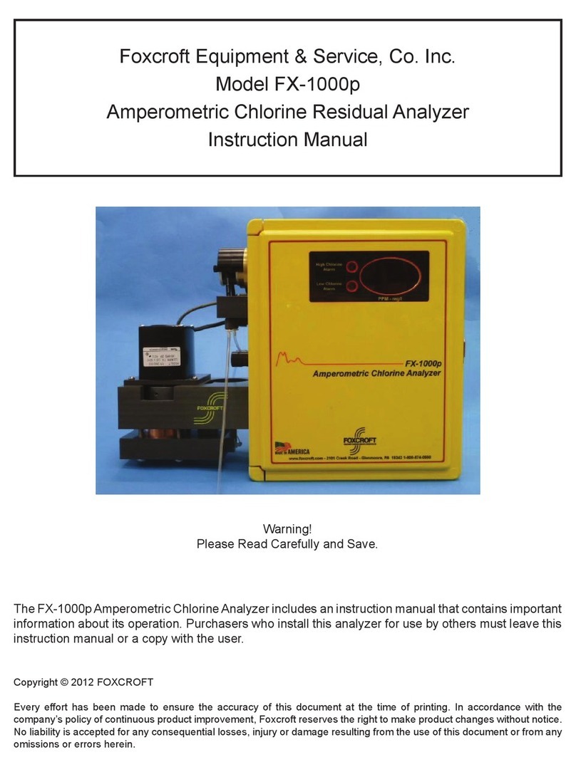
Foxcroft FX-1000p User manual

Foxcroft

Foxcroft FX-1000p User manual

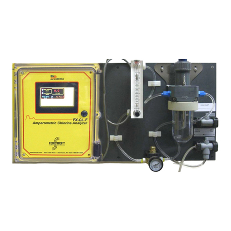
Foxcroft FX-CL-F User manual

Foxcroft

Foxcroft FX-CL-F User manual

Popular Measuring Instrument manuals by other brands

Ono Sokki CF-4700 user guide

Ono Sokki

Ono Sokki CF-4700 user guide

red lion PAX2A manual

red lion

red lion PAX2A manual

Pro's Kit MT- 4615 user manual

Pro's Kit

Pro's Kit MT- 4615 user manual

Sensor Therm METIS M311 user manual

Sensor Therm

Sensor Therm METIS M311 user manual

FRO­NIUS TS 5kA-3 quick start guide

FRO­NIUS

FRO­NIUS TS 5kA-3 quick start guide

POTOMAC INSTRUMENTS INC. AA-51 instruction manual

POTOMAC INSTRUMENTS INC.

POTOMAC INSTRUMENTS INC. AA-51 instruction manual

AirPro AP500 Operation user's manual

AirPro

AirPro AP500 Operation user's manual

Unit UT345C user manual

Unit

Unit UT345C user manual

Challenger Optics CO-OTDR-CWDM-10M Series user guide

Challenger Optics

Challenger Optics CO-OTDR-CWDM-10M Series user guide

WhisperPower WBM Modular Smart Shunt installation manual

WhisperPower

WhisperPower WBM Modular Smart Shunt installation manual

Unit UTE9802+ user manual

Unit

Unit UTE9802+ user manual

MH Corbin BLUESTAR NC350 user manual

MH Corbin

MH Corbin BLUESTAR NC350 user manual

Unit UTS1000 Series Service manual

Unit

Unit UTS1000 Series Service manual

FARM SCAN Jackal v2 General description

FARM SCAN

FARM SCAN Jackal v2 General description

Blackmagicdesign HyperDeck Studio Getting started

Blackmagicdesign

Blackmagicdesign HyperDeck Studio Getting started

MPFiltri ICM Guide

MPFiltri

MPFiltri ICM Guide

BZB Gear BG-AVTPG-A user manual

BZB Gear

BZB Gear BG-AVTPG-A user manual

EPE Conseil ESI 23 quick start guide

EPE Conseil

EPE Conseil ESI 23 quick start guide

manuals.online logo
manuals.online logoBrands
  • About & Mission
  • Contact us
  • Privacy Policy
  • Terms and Conditions

Copyright 2025 Manuals.Online. All Rights Reserved.