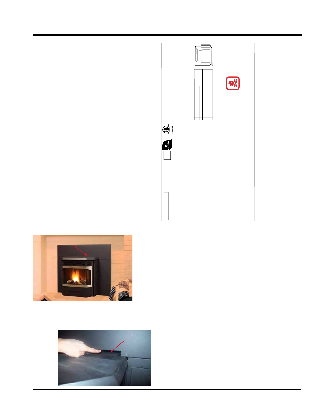
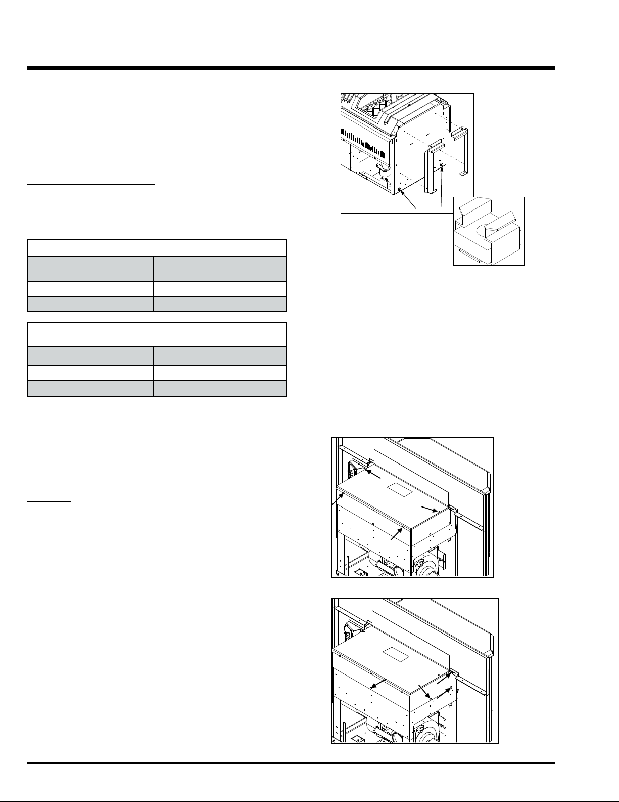
FPI Greenfire GFI55-2 User manual

FPI FIREPLACE PRODUCTS INTERNATIONAL, LTD. 6988 VENTURE ST., DELTA, BC, CANADA V4G 1H4
920-625 12.20.22
Greenre®GFI55-2
WARNING:
Improper installation, adjustment, alteration,
service or maintenance can cause injury,
property damage, or loss of life.
Refer to this manual. For assistance or
additional information consult an authorized
installer or service agency.
FOR YOUR SAFETY:
Do not store or use gasoline or other ammable
vapours and liquids in the vicinity of this or
any other appliance.
Installation and service must be performed
by an authorized installer or service agency.
Tested by:
IMPORTANT: SAVE THESE INSTRUCTIONS
TECHNICAL MANUAL
Fireplace
Insert Pellet Stove
French Manual: https://bit.ly/3l4sqbo
Manuel en Français : https://bit.ly/3l4sqbo
4001609

Greenre Pellet Insert Technical Manual
2
Safety Note: If this stove is not properly installed, a house fire may result. For your safety,
follow the installation instructions, contact local building, re ocials, or authority having jurisdiction about restrictions
and installation inspection requirements in your area.
The authority having jurisdiction should be consulted before installation to determine the need to obtain a permit.
Emissions and Efficiency - GFI55-2: This manual describes the installation and operation of the Regency GFI55-2
pellet heater. This heater is U.S. ENVIRONMENTAL PROTECTION AGENCY certified to comply with 2020 particulate
emission standards. Under specific test condition this heater has been shown to deliver heat at rates raging from:
7,751 - 32,739 Btu/hr
Efficiency: 75%* HHV (PFS TECO 21-694)
*When using optional top vent adaptor kit (GF55-920) and 3'' to 6'' flue adaptor (946-792). See manual for further
information.
FIRE EXTINGUISHER AND SMOKE DETECTION: All home with a pellet burning stove should have at least one
fire extinguisher in a central location known to all the household. Smoke detectors and carbon monoxide detectors
should be installed maintained in the room containing the stove. If it sounds the alarm, correct the cause but do not
deactivate. You may choose to relocate the smoke the smoke detection device within the room; DO NOT REMOVE
THE SMOKE OR CARBON MONOXIDE DETECTORS FROM THE ROOM.
WARNING: This wood heater needs periodic inspection and repair for proper operation. It is against federal regulation
to operate this wood heater in a manner inconsistent with operating instructions in this manual.
WARNING: This wood heater has a manufacturer set minimum low burn rate that must not be altered. It is against
federal regulations to alter this setting or other wise operate this wood heater in a manner inconsistent with operating
instructions in this manual.

Greenre Pellet Insert Technical Manual 3
TABLE OF CONTENTS
SAFETY LABEL
Copy of Serial No. Decal ............................................4
Decal Location ..........................................................4
UNIT DIMENSIONS
GFI55-2 Fireplace Pellet Insert ...................................5
GFI55-2 Fireplace Pellet Insert w/ Top Vent Adaptor ....6
INSTALLATION
Important Safety Information.....................................7
Safety Warnings & Recommendations.........................7
Removing Pellet Insert From Pallet .............................8
Opening the Door......................................................8
Locating the Pellet Appliance......................................8
Clearances to Combustibles........................................9
Fireplace Specications..............................................9
Pedestal & Leveling Legs ...........................................9
Hopper Cover & Adjusting Hopper Height....................9
Exhaust & Fresh Air Intake Location .........................10
Outside Fresh Air Connection ...................................10
Masonry Fireplace Insert Install................................10
Positive Flue Connection without a Full Reline (USA only)
..............................................................................11
Top Vent Adaptor Kit & 3" to 6" Flue Adaptor ............12
Installation and Removal of COntrol Panel in the
Surround Panel .......................................................13
Assembly and Installation of Insert Surround Panels ..13
Plated Door Installation ...........................................14
Thermostat Installation............................................14
Slider/Damper Set-Up............................................. 15
TROUBLESHOOTING
Troubleshooting FAQ's .............................................16
Wiring Diagram .......................................................18
PARTS LIST
Parts List & Components..........................................19
WARRANTY
Warranty ................................................................24
*This manual is designed for the technician in conjunction with the owner’s manual.*

Greenre Pellet Insert Technical Manual
4
SAFETY LABEL
On the GFI55-2 the safety label is located
on the hopper cover behind the top
faceplate.
Certified for use in Canada & USA
Certifié pour installation au
Canada et aux Etats-Unis.
DATE OF MANUFACTURE /
DATE DE FABRICATION:
J F M A M J J A S O N D 2022 2023 2024 2025 2026
CAUTION:
Hot while in operation. DO
NOT touch, keep children,
clothing & furniture away.
Contact may cause skin
burns. See nameplate &
instructions
ATTENTION:
Chaud pendant le fonctionnement.
NE PAS toucher, garder les enfants,
les vêtements et les meubles à
distance. Tout contact peut
provoquer des brûlures de la peau.
Voir plaque signalétique et
instructions
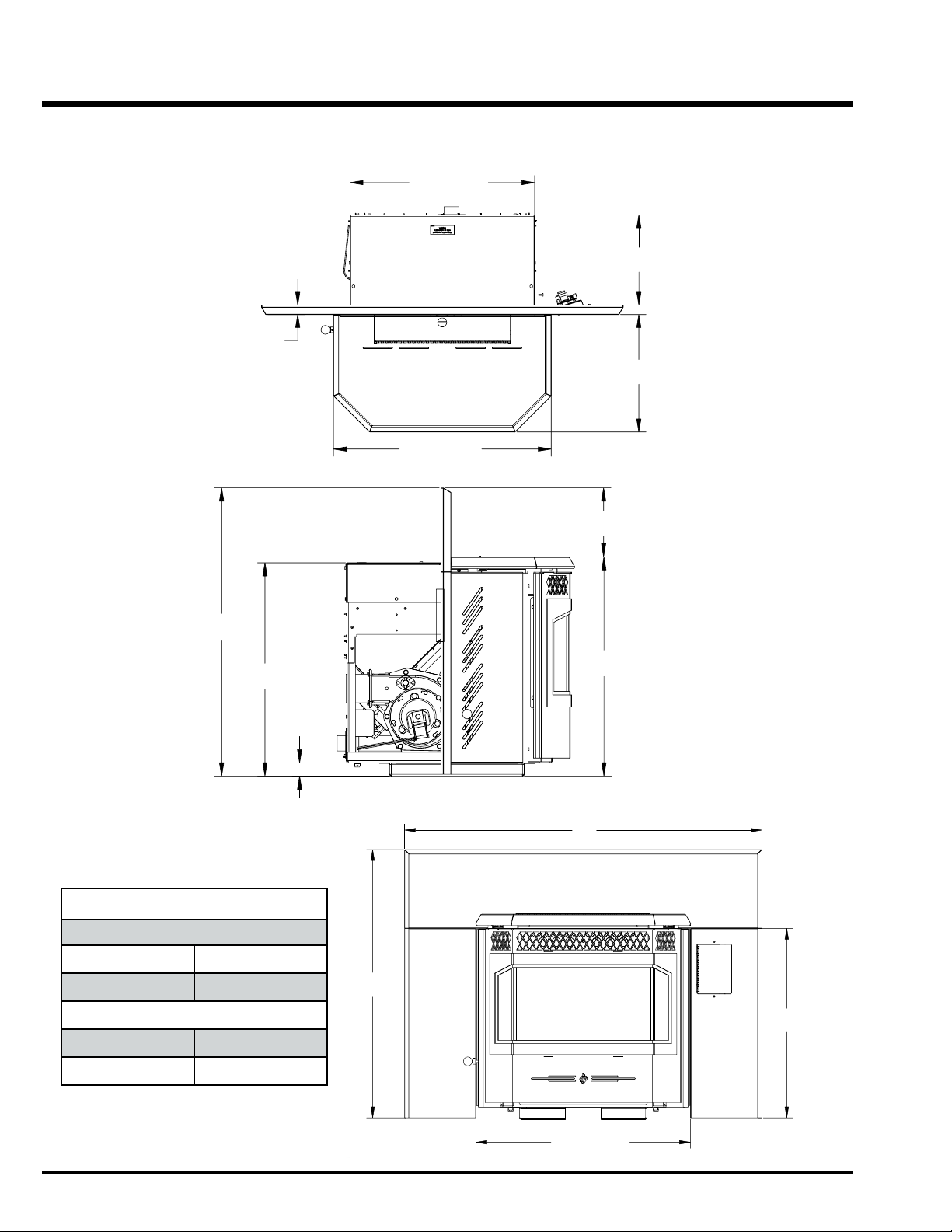
A Sidewall to Unit (Du mur latéral à l'appareil) 8” (203 mm)
B Top of unit to an unshielded 8” (203 mm) mantle
(Du sommet de l'appareil à un manteau de foyer non blindé) 8” (203 mm)
C Unit to top facing (protruding ¾” [19 mm])
(
De l'appareil au sommet du parement (dépassant de ¾ po [19 mm])
8” (203 mm)
D Unit to side facing (protruding ¾” [19 mm])
(
De l'appareil au côté du parement (dépassant de ¾ po [19 mm])
8” (203 mm)
E From door opening of unit to edge of floor protection
(De l'ouverture de la porte de l'appareil au rebord de la protection de plancher)
6” (152 mm)
F From side of unit to edge of floor protection
(Du côté de l'appareil au rebord de la protection de plancher) 6” (152 mm)
Combustible floors must be protected by a non-combustible material. - See Owners Manual. Le
plancher combustible doit être protégé par un matériel non combustible. - Consulterle manuel.
B
A
D
C
Adjacent wall / Mur adjacent
FE
FPI Model /
modèle
920-623
580
Serial No. / No. de série:
Greenfire Model / Modèle:
GFI55-2
(insert/encastrable)
Manufactured in Canada for /
Fabriqué au Canada pour:
FPI Fireplace Products
International Ltd.
Delta, BC, Canada
PFS TECO
REPORT
#21-695
Refer to Intertek’s Directory of Building Products for detailed information. / Reportez-vous à
l'annuaire Intertek des produits du bâtiment pour obtenir des informations détaillées.
Ouput Rating (puissance de sortie): 7,751 to 32,739 BTU/Hr (2.27 to 9.59 kWh)
Listed Room Heater, Pelletized Fuel Type (Appareil de chauffage à granules certifié)
Suitable For Mobile Home Installation (approuvé pour installation dans une maison mobile)
Certified to (agréé):
ULC-S628-93 (R 2016), ASTM E1509-22
This pellet appliance has been tested and listed for use in manufactured homes in accordance with Oregon Administration Rules 814-23-900 through 814-23-909.
Install and use only in accordance with the Manufacture’s installation and operating instructions. Contact local building or fire officials about restrictions and
installation inspection in your area. Do not connect this unit to a chimney flue serving another appliance. See local building codes and manufacturers instructions
for precautions required for passing a chimney through a combustible wall or ceiling. Electrical rating: 120 volts, 60 hz, 4.3 Amps. Route cord away from the
heater / Cet appareil a été testé et certifié pour être utilisédans des maisons mobiles en accord avec les règles administratives de l'Oregon 814-23-900 à
814-23-909. Installeret utilisercet appareil seulement selon les instructions d'installation et d'utilisation du fabricant. Contacterles autorités locales concernant les
restrictions et les inspections d'installation. Ne pas raccorder cet appareil à une cheminée desservant un autre appareil. Consulterles codes dubâtiment locaux et
les instructions du fabricant pour les précautions à prendre lorsqu'une cheminée doit être installée à travers un mur ou un plafond combustible. PUISSANCE
ÉLECTRIQUE : 120 Volts, 60 Hz, 4.1 Amps. Placerle câble électrique loin de la chaleur.
For Use With Only Pelletized Wood fuels. Keep viewing and ash removal doors tightly closed during operation. Only replace glass with ceramic glass.
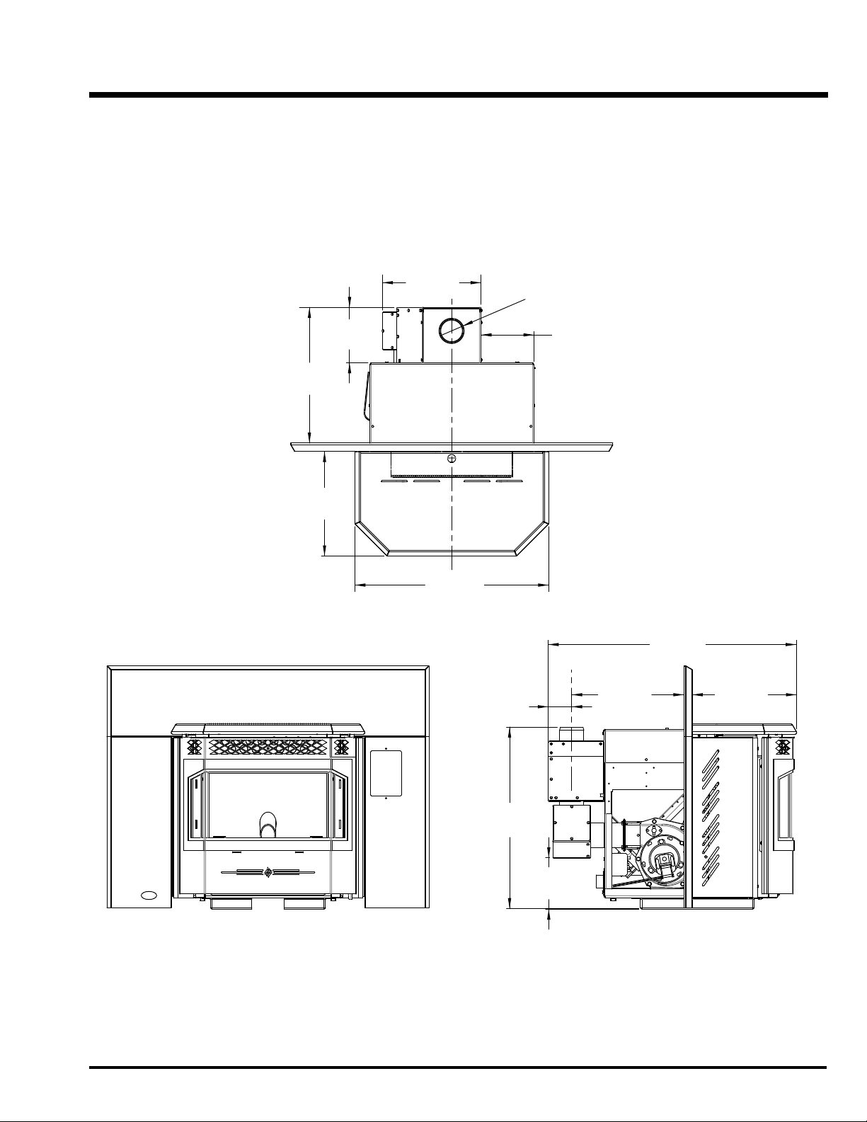
Components required for installation: a 3 inch (75 mm) or 4inch (100 mm) listed PL vent, complete with components. Insert and Hearth mount installations; a
listed single wall chimney liner may be used. Inspect and clean Exhaust Venting system frequently / À utiliser avec des combustibles sous forme de granules
uniquement. Utiliser seulement lorsque les portes avant et la porte du retrait descendressont fermées. Si une ou des vitres doivent être remplacées, utiliser
seulement de la vitrocéramique. Pièces requises pour l'installation :uneévacuation PL certifiéede 3 po / 75 mm ou de 4 po / 100m m avec ses composantes. Les
installations de l'encastrable et dumontage dufoyer :une doublure de cheminée à simple paroi peut être utilisée. Inspecter et nettoyer fréquemment le système
de ventilation et d'évacuation.
To Start Stove: Press the ON / OFF button. If the auger needs to be primed, press the Manual Auger Feed button until fuel starts to drop into the
Burn Pot.
To Operate Stove: MANUAL MODE: When a fire has been established the stove settings are adjustable. / HIGH/LOW MODE: (Requires a thermostat)
When the thermostat calls for heat the stove settings are adjustable. When the thermostat contacts open, the HEAT LEVEL and Fans will drop down to
the LOW setting until the thermostat contacts close again. / AUTO/OFF MODE: (Requires a thermostat) When the thermostat contacts close, the unit will
light automatically. Once up to temperature the stove settings are adjustable. When the thermostat contacts open, the stove will drop down to the LOW
settings for 30 minutes. If within the 30 min the thermostat contacts close, the HEAT LEVEL will return to previous MANUAL setting or if the thermostat
contacts remain open the stove begin its shutdown routine. To Turn Off Stove: MANUAL and HI / LOW mode: Press the ON / OFF button; AUTO / OFF
mode: Turn the thermostat down or off.
Pour démarrer le poêle : Appuyer sur le bouton “ON/OFF”. Si la vis sans fin doit être amorcée, appuyer sur le bouton manuel d’alimentation de la vis
jusqu'à ce que les granules se déversent dans le pot de combustion.
Pour faire fonctionner le poêle : MODE MANUEL: Lorsque le feu est bien établi, les réglages peuvent être ajustés. / MODE “HIGH/LOW”: (Nécessite un
thermostat) Lorsque le thermostat requiert de la chaleur, les réglages peuvent être ajustés. Lorsque les contacts du thermostat s’ouvrent, le réglage du
niveau de chaleur et les ventilateurs s’ajusteront au réglage “bas” jusqu'à ce que les contacts du termostat se referment. / MODE “AUTO/OFF”: (Nécessite
un thermostat) Lorsque les contacts du thermostat ferment, le poêle s’allumera automatiquement. Lorsque la température adéquate est atteinte, les
réglages peuvent être ajustés. Lorsque les contacts du thermostat s’ouvrent, le poêle s’ajustera aux réglages bas pendent 30 minutes. Si les contacts du
thermostat se ferment au cours de ces 30 minutes, le réglage de niveau de chaleur retournera en réglage MANUEL ou si les contactsdu thermostat
restent ouverts, le poêle entamera le processus d'arrêt.
Pour éteindre le poêle: MODE MANUEL ET “HIGH/LOW”: Appuyer sur le bouton “ON/OFF”. MODE
“AUTO/OFF”: Baisser le thermostat ou l’éteindre.
DO NOT REMOVE THIS LABEL /
NE PAS RETIRERCETTE ÉTIQUETTE
This wood heater needs periodic inspection and repair for proper operation. Consult the owner’s manual for further
information. It is against federal regulations to operate this wood heater in a manner inconsistent with the operating
instructions in the owner’s manual. U.S. ENVIRONMENTAL PROTECTION AGENCY Certified to comply with 2020
particulate emission standards. Under specific test conditions. this heater has been shown to have a particulate
emission level of 1.8 g/hr. Ce poêle à granules nécessite une inspection et une réparation périodiques pour un
fonctionnement correct. Consulter le manuel du propriétaire pour plus d’informations. Il est contraire aux règlements
fédéraux d'utiliser ce poêle à bois d'une manière non conforme aux instructions d'utilisation du manuel du
propriétaire. Certifié U.S. ENVIRONMENTAL PROTECTION AGENCY pour être conforme aux normes d'émission
de particules de 2020. Dans des conditions de test spécifiques, il a été démontré que ce poêle a un niveau
d'émission de particules de 1,8 g/hr.
INSTALLED AS A FIREPLACE INSERT STOVE MODEL / INSTALLÉCOMME
MODÈLE DE POÊLE AUTOPORTANT
Minimum clearances to combustible materials / Dégagements minimaux par rapport aux matériels combustibles :
GFI55-2 DECAL LOCATION
When locating the rating plate on a GFI55-2 the surround must be
removed. Once the Surround has been removed the rating plate will be
located on the top of the unit as shown below.
DO NOT REMOVE DECAL FROM UNIT.

Greenre Pellet Insert Technical Manual 5
UNIT DIMENSIONS
GFI55-2 FIREPLACE PELLET INSERT
225/16"
(567mm)
13/8" (35mm)
303/16"
(766mm)
71/4"
(183mm)
2215/16"
(582mm)
203/8" (517mm)
241/16" (610mm)
11/16"
(26mm)
13"
(329mm)
10"
(253mm)
225/16"
(567mm)
13/8" (35mm)
303/16"
(766mm)
71/4"
(183mm)
2215/16"
(582mm)
203/8" (517mm)
241/16" (610mm)
11/16"
(26mm)
13"
(329mm)
10"
(253mm)
FACEPLATE DIMENSIONS
Regular Faceplate
(A) Height 30" (761mm)
(B) Width 39-15/16" (1014mm)
Oversize Faceplate
(A) Height 33" (838mm)
(B) Width 45-15/16" (1167mm)
2315/16" (609mm)
B
A
213/16"
(538mm)

Greenre Pellet Insert Technical Manual
6
GFI55-2 FIREPLACE PELLET INSERT WITH TOP VENT ADAPTOR
6
GFI55-2 FIREPLACE PELLET INSERT WITH TOP VENT ADAPTOR
12 - 1/4”
(311mm) Ø 3”
(76mm)
6 - 9/16”
(167mm)
6 - 7/8”
(175mm)
16 - 7/8”
(429mm)
13”
(330mm)
24 - 1/16”
(611mm)
13”
(330mm)
13 - 7/8”
(352mm)
3”
(76mm)
22 - 1/2”
(572mm)
6 - 3/8”
(162mm)
30 - 3/4”
(781mm)

Greenre Pellet Insert Technical Manual 7
INSTALLATION
IMPORTANT SAFETY INFORMATION
Failure to follow these instructions may result in property damage, bodily
injury or even death.
Contact your local building or re ocial to obtain a permit and any
information on installation restrictions and inspection requirements for
your area.
To prevent the possibility of a re, ensure that the appliance is properly
installed by adhering to the installation instructions. A Greenre dealer will
be happy to assist you in obtaining information with regards to your local
building codes and installation restrictions.
Be sure to maintain the structural integrity of the home when passing a
vent through walls, ceilings, or roofs.
The stove's exhaust system works with negative combustion chamber
pressure and a slightly positive chimney pressure. It is very important to
ensure that the exhaust system be sealed and airtight. The ash pan and
viewing door must be locked securely for proper and safe operation of
the pellet stove.
Do not burn with insucient combustion air. A periodic check is
recommended to ensure proper combustion air is admitted to the combustion
chamber. Setting the proper combustion air is achieved by adjusting the
slider damper located on the left side of the stove. Refer to "Slider/Damper
Set-up" section. When installing the stove in a mobile home, it must be
electrically grounded to the steel chassis of the home and bolted to the
oor. Make sure that the structural integrity of the home is maintained
and all construction meets local building codes.
Minor soot or creosote may accumulate when the stove is operated under
incorrect conditions such as an extremely rich burn (black tipped, lazy
orange ames).
If you have any questions with regard to your stove or the above-mentioned
information, please feel free to contact your local dealer for further
clarication and comments.
SAFETY WARNINGS &
RECOMMENDATIONS
CAUTION:
Do not connect to any air distribution duct or system.
Do not burn garbage or ammable uids such as gasoline, naptha
or engine oil.
Unit hot while in operation. Keep children, clothing and furniture
away. Contact may cause skin burns.
SOOT: Operation of the stove with insucient combustion air will result in
the formation of soot which will collect on the glass, the heat exchanger,
the exhaust vent system, and may stain the outside of the house. This is
a dangerous situation and is inecient. Frequently check your stove and
adjust the slider/damper as needed to ensure proper combustion. See
"Slider/Damper Setting".
CLEANING: There will be some build up of y ash and small amounts of
creosote in the exhaust. This will vary due to the ash content of the fuel
used and the operation of the stove. It is advisable to inspect and clean
the exhaust vent semi-annually or every two tons of pellets.
ELECTRICAL: The use of a surge protected power bar is highly
recommended. The unit must be grounded. The grounded electrical
cord should be connected to a standard 115 volts (4.6 Amps), 60 hertz
electrical outlet. Be careful that the electrical cord is not trapped under
the appliance and that it is clear of any hot surfaces or sharp edges and
also must be accessible. If this power cord should become damaged, a
replacement power cord must be purchased from a Greenre dealer. This
unit's maximum power requirement is 520 watts.
GLASS: Do not abuse the glass by striking or slamming the door. Do not
attempt to operate the stove with broken glass. The stove uses ceramic
glass. Replacement glass must be purchased from a Greenre dealer.
Do not attempt to open the door and clean the glass while the unit is in
operation or if glass is hot.
To clean the glass, use a soft cotton cloth and mild window cleaner, gas
or wood stove glass cleaner, or take a damp paper towel and dip into the
y ash. This is a very mild abrasive and will not damage the glass.
FLAMMABLE LIQUIDS: Never use gasoline, gasoline-type lantern fuel,
kerosene, charcoal lighter uid, or similar liquids to start or “freshen up”
a re in the heater. Keep all such liquids well away from the heater while
it is in use.
SMOKE DETECTOR: Smoke detectors should be installed and maintained
in the structure when installing and operating a pellet burning appliance.
OPERATION: The ash pan and door must be closed securely for proper
and safe operation of the pellet stove. Also ensure all gaskets on the door
are checked and replaced when necessary.
INSTALLATION: Be sure to maintain the structural integrity of your home
when passing a vent through walls, ceilings, or roofs. It is recommended
that the unit be secured into its position in order to avoid any displacement.
DO NOT INSTALL A FLUE DAMPER IN THE EXHAUST VENTING
SYSTEM OF THIS UNIT.
DO NOT CONNECT THIS UNIT TO A CHIMNEY FLUE SERVING
ANOTHER APPLIANCE.
FRESH AIR: Outside Fresh Air connection is optional. Must be connected to
all units installed in Mobile and “Air Tight Homes” (R2000) or where required
by local codes. Consider all large air moving devices when installing your
unit and provide room air accordingly. Limited air for combustion may result
in poor performance, smoking and other side eects of poor combustion.
If you have any questions with regards to your stove or the abovementioned
information, please feel free to contact your Greenre dealer for further
clarication and comments.
SINCE FPI HAS NO CONTROL OVER THE INSTALLATION OF YOUR STOVE,
FPI GRANTS NO WARRANTY IMPLIED OR STATED FOR THE INSTALLATION
OR MAINTENANCE OF YOUR STOVE. THEREFORE, FPI ASSUMES NO
RESPONSIBILITY FOR ANY CONSEQUENTIAL DAMAGE(S).
IMPORTANT SAFETY INFORMATION

Greenre Pellet Insert Technical Manual
8
INSTALLATION
1. Check clearances to combustibles. See "Clearance to Combustibles"
section.
2. Do not obtain combustion air from an attic, garage or any unventilated
space if enough air is available. Combustion air may be obtained from
a ventilated crawl space.
3. Do not install the stove in a bedroom.
4. You can vent the stove through an exterior wall behind the unit or
connect it to an existing masonry or metal chimney (must be lined if
the chimney is over 6” (15 cm) diameter, or over 28 inches² (180 cm²)
cross sectional area). An interior vent can be used with approved pipe
passing through the ceiling and roof.
REMOVING PELLET INSERT
FROM PALLET
To remove your new insert from its pallet, remove the two (2) screws
securing the bottom to the pallet.
Fireplace Insert:
There is one screw on either side of the bottom. See gure 2.
Figure 2: Removing GFI55-2 From Pallet.
LOCATING THE PELLET APPLIANCE
5. Locate the stove in a large and open room that is centrally located in
the house. This will optimize heat circulation.
6. The power cord is 8 feet (2.43 m) long and may require a grounded
extension cord to reach the nearest electrical outlet.
OPENING THE DOOR
The door lever can be found inbehind the right side of the door frame. To open the door, pivet the lever outwards and upwards until it unlocks.

Greenre Pellet Insert Technical Manual 9
GFI55-2 PELLET INSERT
CLEARANCES TO COMBUSTIBLES
The replace insert is certied to be installed into a masonry replace only
and/or zero clearance wood burning factory built replace where allowed
by local codes. This model includes a surround faceplate and a pedestal.
When installing this unit, ensure that the pedestal is removed from the
inside of the hopper and installed on the bottom of the unit.
From the body of the heater to the:
Side Wall 8" (203mm) minimum
Facing on Masonry Fireplace: 8" (203mm) minimum
8” (203mm) mantle: 8" (203mm) minimum
INSTALLATION OF PEDESTAL AND LEVELLING LEGS
There are two parts to the GFI55-2 insert pedestal and they can be found
inside the hopper. Place unit on its back. Two (2) hex head screws are used
on each side of the pedestal (refer to Figure 22). Using a 5/16” wrench
or socket, secure the pedestal to the bottom of the unit.
OPTIONAL:
There are two (2) leveling legs and they can be found inside the manual
bag. Each leveling leg consists of a long bolt, a hex nut, a washer, and a
square bolt with clip (see Figure 23). For installation of the leveling legs the
unit should be on its back and a ½” wrench is required for adjustments.
Install the square bolts into the square holes in the back corners of the
bottom. The square bolt should be inserted from inside the unit so that
the clip will be facing up.
Thread hex nut onto the bolt till it is approximately 1” (25 mm) from the
bolt head, slide washer onto bolt. Thread the bolt into the square nut so
length of the bolt shown is the approximately height needed for leveling.
When the unit is up right and the bolts can be adjusted to the exact height
required. To lock the bolts at a height tighten the hex nut and washer
against the square bolt.
Leveling Legs
Figure 22: Installing Pedestal
Figure 23: Square Bolt
INSTALLING HOPPER COVER AND
ADJUSTING HOPPER HEIGHT
The hopper cover initially comes upside-down on top of the hopper.
To install the hopper cover ip the cover over and fasten in place with
four T-20 screws (see Figure 24).
The back height of this unit can be set to one (1) of three (3) heights;
19½” (495mm), 21” (537mm), 22¼” (565mm). The hopper should be
set to the maximum height that can be used in the installation.
To change the height of the hopper back up or down, remove the seven
(7) T-20 screws, three (3) on each side and one (1) on the back. The
screw placement is shown Figure 25. Move the hopper assembly to the
required setting and replace the screws. When the hopper back is in
place it is recommended that silicone is used to seal the bottom lip of the
hopper back and sides.
Figure 24: Hopper Cover Screw Placement
Figure 25: Hopper Extension Screw Placement
INSTALLATION
FIREPLACE SPECIFICATIONS
Your replace opening requires the following minimum sizes:
Height 55 lbs hopper (standard)
42 lbs hopper (adjusted)
22.75" (578mm)
19.5" (495mm)
Width 26" (660mm)
Depth 15" (381mm)
Your replace opening requires the following minimum sizes when using
the top vent adaptor:
Height 55 lbs hopper (standard) 23.25" (591mm)*
Width 26" (660mm)
Depth 18" (457mm)
*NOTE: When using the top vent adapter, the hopper must be set to the
standard height (55lbs, 22¼”).

Greenre Pellet Insert Technical Manual
10
EXHAUST AND FRESH AIR INTAKE LOCATION
EXHAUST:
Base of unit to center of ue 9-1/16" (229mm)
Side of unit to center of ue 6-1/8" (156mm)
Center of unit to center of ue 5-3/4" (146mm)
FRESH AIR INTAKE:
Base of unit to center of intake 3-7/16" (87mm)
Side of unit to center of intake 10-7/8" (277mm)
Center of unit to center of
intake
1" (25mm)
INSTALL VENT AT CLEARANCES SPECIFIED BY THE VENTING MANU-
FACTURER.
1"
(25mm)
5 3/4"
(146mm)
3 7/16"
(87mm)
10 7/8"
(277mm)
6 1/8"
(156mm)
9 1/16"
(229mm)
Figure 26: Insert Inlet and Outlet Location
OUTSIDE FRESH AIR CONNECTION
Outside fresh air is mandatory when installing this unit in airtight
homes and mobile homes.
A Fresh-air intake is strongly recommended for all installations.
Failure to install intake air may result in improper combustion as well as
the unit smoking during power failures.
When connecting to an outside fresh air source, do not use plastic or
combustible pipe. A 2” minimum (51mm) ID (inside diameter) steel,
aluminum or copper pipe should be used. It is recommended, when you
are installing a fresh air system, to keep the number of bends in the pipe
to a minimum.
2" ID
(51 mm) Optional
Elbow
Outside
Wall
Figure 27: Outside Air Connection
MASONRY FIREPLACE INSERT INSTALLATION
The GFI55-2 requires a surround faceplate and a pedestal. When install-
ing this unit, ensure that the pedestal is removed from the inside of the
hopper and installed on the bottom of the unit. Refer to "Installation of
Pedestal and Leveling Legs".
Adjust hopper height - refer to "Installing Hopper Cover and Adjusting Hop-
per Height" and assemble surround panel. See "Installation and Removal
of Control Panel in the Surround Panel" and "Assembly and Installation
of Insert Surround Panels" before starting installation.
A non-combustible hearth pad must cover combustible ooring under-
neath, as well as 6” (150mm) in front of the heater and 6” (150mm) to
the side of the heater
1. Install the hearth pad, if required.
2. Lock the replace damper in the open position.
3. Install a positive ue connector at the replace damper.
4. Connect a tee or 90° elbow to the exhaust pipe.
5. This replace insert must be installed with a continuous chimney liner
of 3 or 4” diameter extending from the replace insert to the top of
the chimney. The liner must conform to type 3 requirements of CAN/
ULC S635. For lengths below 25' use 3" and increase to 4" if longer.
6. (Recommended) Install fresh air intake either through the back of the
replace or through the positive ue connector.
Floor
Protection
Combustible Floor
Masonry Fireplace
Min. 6"
Rain Cap
Steel Plate or Flashing
Mantel (8" deep)
Fresh-air intake
Clean-out tee
If holes already exist
fresh-air intake can
be taken through the
back of the fireplace
or through the ash
dump.
Damper Removed
or Fastened Open
Min. 8" from
top of stove
Figure 28: Installation of Fireplace Insert
INSTALLATION

Greenre Pellet Insert Technical Manual 11
When installing the insert into a masonry replace DO NOT remove any
bricks or masonry, with the following exception; masonry or steel, including
the damper plate, may be removed from the smoke shelf and adjacent
damper frame if necessary to accommodate a chimney liner. Provided that
their removal will not weaken the structure of the replace and chimney,
and will not reduce protection for combustible materials to less than that
required by the national building code.
POSITIVE FLUE CONNECTION WITHOUT A FULL RELINE
(USA ONLY)
This unit does not require a full reline (in USA only) when installing
into a masonry replace, however, it is recommended to ensure
proper drafting of the appliance. This type of application is not
recommended.
IMPORTANT: Ensure the chimney and rebox are cleaned and free of
all debris, including soot and ashes, before proceeding with this instal-
lation. If it is not clean, soot may be blown into the room through the
unit’s blower. Ensure the replace and chimney have not deteriorated in
any way. If there is any sign of corrosion or damage in the chimney the
unit can not be installed. This unit can be installed in a masonry replace
built to (UBC 37 or ULC S628 standards) or a factory built replace (built
to UL 127 or ULC S610 standards).
1. Install the hearth pad. The oor 6” (150mm) in front of the unit and
6” (150mm) to each side of the unit must be protected with a non-
combustible hearth pad.
2. The vent connector from the insert must extend a minimum of 18”
above the chimney seal plate. The chimney seal plate area must be
sealed to prevent the exhaust from the chimney from coming back
into the replace and prevent air from the replace from entering the
chimney which will aect proper drafting of appliance.
A qualied installer should evaluate the existing replace to determine
the best method for achieving a positive ue connection between
the vent pipe or liner and the chimney. Whatever method used must
eectively seal the area to prevent room air passage to the chimney
cavity of the replace. A couple examples of Approved Methods of
Achieving a Positive Flue Connection are:
a) Secure a seal-o plate (i.e. 22-gage sheet steel) in the masonry
replace throat using masonry screws.
b) Pack non-combustible material (i.e. rockwool) around the vent pipe
or using a ue adapter.
3. Set leveling leg to approximate height.
IMPORTANT: The chimney seal plate must be removed for the annually
chimney cleaning as ash will build up on top of the plate.
Be aware that this type of application may have a negative eect on
performance not covered under warranty.
Floor Protection
Combustible Floor
Masonry Fireplace
Chimney must be completely
sealed with a non-combustible
material and maybe removed
annually for cleaning.
Top of vent pipe
must be 18"
(45.7cm) minimum
above the chimney
seal plate.
The existing chimney can
not be corroded or
damaged in any way.
Mantel (8" deep)
Min. 8" from
top of stove
Min. 6"
Figure 29: Masonry replace positive ue installation
INSTALLATION
When installing the replace insert into a zero clearance replace, where
allowed by local codes, DO NOT cut or modify any factory rebox parts.
If the replace insert does not t into a zero clearance replace we rec-
ommend you use an Greenre freestanding model and install as a hearth
mounted unit. Install a 3” (76mm) ex pipe from the stove to the top of
the chimney. Refer to "Hearth Mount Installation".

Greenre Pellet Insert Technical Manual
12
TOP VENT ADAPTOR KIT & 3” (76 MM) TO 6” (152 MM) FLUE ADAPTOR (APPROVED
FOR VERTICAL INSTALLATIONS ONLY)
*In order to achieve the maximum rated eciency of 75% HHV purchase of a top vent adaptor kit (GF55-920) is required.
Use the sheet metal screws provided to attach the kit to the rear of the unit as shown. Please see kit instruction manual for more
detailed installation instructions.
The stove must also be connected to a 6” (152 mm) Class A ue (where permitted) using the 3” (76 mm) to 6” (152 mm) Flue
increaser (946-792).
See separate instruction manual for complete details.
12
TOP VENT ADAPTOR KIT & 3” (76 MM) TO 6” (152 MM) FLUE ADAPTOR (APPROVED
FOR VERTICAL INSTALLATIONS ONLY)
Use the sheet metal screws provided to attach the kit to the rear of the unit as shown. Please see kit instruction manual for more
detailed installation instructions.
Adaptor (???-???).
See separate instruction manual for complete details.
INSTALLATION
Floor Protection
Combustible Floor
Masonry Fireplace
Mantel (8” deep)
Min. 8” from
top of stove
Min. 6”
Damper removed or
fastened open
The existing chimney
can not be corroded or
damaged in any way.
3” to 6” Stainless
Steel Increaser
Rain cap
Steel plate or flashing
3” Stainless Steel
Flex Venting
Top Vent Adapter
Minimum 3 ft.
height of 3” vent
INSTALLATION

Greenre Pellet Insert Technical Manual 13
INSTALLATION AND REMOVAL OF CONTROL PANEL IN THE SURROUND PANEL
When installing the circuit board control panel into the surround panel,
the surround does not need to be assembled. The circuit board will be
found in the rebox.
Place the circuit board control panel on the backside of the right surround
panel so the hinge is on the outside and the top and bottom holes on
the control panel line up with those on the surround. Attach using two
(2) T-20 screws through the front of the surround into the circuit board
control panel (see Figure 30).
After the surround has been assembled and is ready to be installed on
the unit plug the wiring harness into the control panel (see Figure 31).
REMOVAL:
When maintenance is required on the unit the surround must be removed.
Pull the surround straight up till it stops then pull it out about 4” (10cm)
and rest the surround on top of the unit while the control panel is removed
or disconnected.
If electrical connection is required for the maintenance remove the circuit
board control panel from the surround.
If electrical connection is not required for the maintenance remove the
wiring harness from the bottom of the circuit board control.
Plug
Figure 31: Right
Panel - Back
Figure 30: Right
Panel - Front
ASSEMBLY AND INSTALLATION OF INSERT SURROUND PANELS
The trim set for your surround panel must be installed before installing
the surround panel onto the unit, if not already done.
1. To assemble the surround panels, lay the panels face down on a soft
at surface and align the outer edges of the sides with the top panel.
Using four (4) T-20 screws up through the side panels into the top
(see Figure 32).
Figure 32: Assembled Surround Panel
Figure 33: Installed Surround Panel
2. Place the assembled surround panel around the stove; align the slots
with the screw heads. Push surround in then down to engage the
surround slots on the mounting screws (see Figure 33). Make sure
the top surround panel sits at behind the stove top.
INSTALLATION

Greenre Pellet Insert Technical Manual
14
PLATED DOOR INSTALLATION
TO AVOID PERSONAL INJURY DO NOT REMOVE OR REPLACE
COVER WHEN PELLET STOVE IS HOT!
TOOLS REQUIRED:
a) 11/32" socket
REMOVAL OF DOOR COVER:
When stove is o and cool, open the door. Remove the four (4) #8 hex
nuts around the inside of the glass retainer shown in Figure 37.
Remove door cover from door by gently sliding the studs out of the holes.
If it is dicult to remove the cover, the glass retainer may be pinching
the threads on the studs. Slightly loosen the four (4) screws (by each of
the studs).
REPLACEMENT OF DOOR COVER:
Slide new door cover into place and hand tighten the four (4) #8 hex nuts
around the inside of the glass retainer. Ensure the four screws are also hand
tight and close door. Do not overtighten or you may break screws.
Clean all plated surfaces before starting the stove. Refer to "Cleaning
Plated Surfaces in Routine Cleaning and Maintenance in the Owner's Manual.
Figure 37: Inner side of door
THERMOSTAT INSTALLATION
1. Install the thermostat by connecting a low voltage millivolt thermostat
to the circuit board jumper location shown below. Connect 2 x 18
gauge wires from the connection points on the back of the control
board to the thermostat (see gure 38).
2. Choose a location for the thermostat, which will eectively heat the
desired area. Do not install close to the unit, typical installation is
10ft - 20ft away in an open area (not hidden).
3. Review each of the three control switch positions with the
consumer.
Remove jumper
wire and install
thermostat wires here.
Figure 38: Thermostat wire placement
INSTALLATION
Note: Model not exactly as shown but depicts the process.

Greenre Pellet Insert Technical Manual 15
INSTALLATION
THE SLIDER / DAMPER HAS BEEN SET AT THE FACTORY. This is
used to regulate the airow through the pellet stove. The slider
damper knob is located on the left cabinet side (see Figure 42) when
facing appliance from the front.
The slider damper factory setting has been set for peak eciency operation/
ecient ame (see Figure 40).
If the re should happen to go out and the heat output indicator has been
set on the lowest setting, the Slider Damper may need to be adjusted by
a qualied technician only. Contact your local dealer.
For troubleshooting purposes the rebox vacuum pressure may need to
be conrmed. This should be done only on a hot stove (operating for
thirty (30) minutes or more) by placing a Magnehelic Pressure Gauge in
the rebox. The reading can be taken from the ⅛” (3 mm) hole located
in the front of the rebox under the door (see Figure 41). The factory
setting should read approximately 0.065 inches of water column
on the high re setting.
Slider
Damper
Exhaust
Channel
Exhaust Blower
Note: Some parts
have been removed in order
to see components more clearly.
Figure 39: Slider / Damper
The easiest way to make sure that an ecient ame is achieved is to
understand the characteristics of the re.
• A tall, lazy ame with dark orange tips requires more air – Open slider
(pull out) slightly.
• A short, brisk ame, like a blowtorch, has too much air – Close slider
(push in) slightly.
• If the ame is in the middle of these two characteristics with a bright
yellow/orange, active ame with no black tips then the air is set for proper
operation.
Figure 40: Ecient Flame
SPECIAL NOTES:
Pellet quality is a major factor in how the Pellet stove will operate. If the
pellets have a high moisture content or ash content the re will be less
ecient and has a higher possibility of the re building up and creating
clinkers (hard ash build-up).
Figure 41: Hole for Pressure test with Magnehelic Gauge
Figure 42: Damper Knob Location
SLIDER / DAMPER SET-UP

Greenre Pellet Insert Technical Manual
16
TROUBLESHOOTING
DO NOT:
• Service the stove with wet hands. The stove is an electrical appliance, which may cause a shock hazard if handled improperly.
• Only qualied technicians should deal with possible internal electrical failures.
• Do not attempt to remove or loosen any screws from inside the rebox without applying penetrating oil (ie. WD40) to any of the screws.
WHAT TO DO IF:
1. The stove will not start.
2. The stove will not operate when hot.
3. The exhaust blower will not function normally.
4. Light # 2 on Heat output bar ashing.
5. Auger light ashes but auger motor does not turn at all
6. The 200 °F (93 °C) high limit temperature sensor has tripped.
7. The convection blower will not function normally.
8. Ignitor- the pellets will not light.
9. Control settings (Heat Level) has no eect on the re.
10. The stove keeps going out.
*NOTE: All troubleshooting procedures should be carried out by qualied technicians or installers.
TROUBLESHOOTING FAQ'S
1. The stove will not start.
Make sure the stove is plugged in and the wall outlet is supplying power.
If the Control Board has been placed in the ON /OFF thermostat mode, then turn the thermostat up to call for heat.
Ensure the burn pot liner is correctly placed in the burn pot.
Check the Heat Level Indicator. - If the # 2 light is ashing, see the # 2 light is ashing.
Check the fuse on the circuit board.
If the unit still does not start, contact your local service dealer for service.
2. The stove will not operate when hot.
Check the Heat Level Indicator if a re is not detected, or if the re has gone out the #3 light will ash because the Exhaust Temperature Sen-
sor’s contacts have opened.
Check the hopper for fuel.
Incorrect air damper setting. - Excessive air may consume the re too quickly before the next drop of fuel, leaving completely unburned fuel in the
burn pot liner. - Insucient air will cause build up, further restricting the air ow through the Burn Pot Liner. This in turn will cause the fuel to burn
cold and very slowly. Fuel may build up and smother the re. In this case clean the burn pot. (NOTE: unit may require a change to the vent
system or installation of fresh air to correct Air to Fuel ratio problems).
Combustion Blower failure. - The Combustion Blower is not turning fast enough to generate the proper vacuum in the re box. Visual Check – is
the blower motor turning.
Check the Exhaust Blower voltage across the blower wires (>=114 V on #5 setting and >= 82 on #1 setting). – Replace the Circuit Board if the
Voltage reading is less than 82 V. with a line voltage >115 V AC.
Check Vacuum levels in the exhaust channel by bypassing the Vacuum Switch, then remove the Vacuum hose from Vacuum Switch. Check exhaust
vacuum readings by placing the open end of the Vacuum Hose on a Magnahelic Gauge (readings must be above .10” W.C. on low re).
If the motor fails to reach a 0.10” W.C. readings, then replace the Combustion Blower.
Poor Quality Fuel – Insucient energy in the fuel to produce enough heat to keep the stove burning or operational.
Exhaust Temperature Sensor failure. – Bypass sensor located on Exhaust Blower. If stove now operates properly, the unit may require cleaning or
a new sensor. Contact your local dealer for service.
Check the fuse on the circuit board.
3. The exhaust blower will not function normally.
Open the left side access panel; check all connections against the wiring diagram.
See “2. The stove will not operate when hot.” section.
4. Light # 2 on Heat output bar ashing
(The Vacuum Switch contacts have opened for more than 15 sec.)
Pinch, break or blockage in Vacuum Hose - Check hose for pinch points or damage, replace or re-route as required. Blow out Vacuum Hose
Blocked Hose Barb on Exhaust Channel - Use a paper clip to clean out Hose Barb or remove the Vacuum Hose from the Vacuum Switch and blow
into the hose to remove blockage.

Greenre Pellet Insert Technical Manual 17
TROUBLESHOOTING
Blocked exhaust / venting system - Have stove and venting cleaned and inspected.
Severe negative pressure in area where unit is installed - Check the operation by opening a window, does this solve the problem? If it does, install
fresh air intake to unit or room. Venting system may require vertical section to move termination into a low pressure zone.
Vacuum Switch failure - Bypass the vacuum switch, if this corrects the problem check for above problems before replacing the Vacuum Switch.
Damage to gray wires between Circuit Board and Vacuum Switch - Inspect wires and connectors
Combustion Blower failure - The Combustion Blower is not turning fast enough to generate the proper vacuum in the Exhaust Channel.
Visual Check; is the blower motor turning? Check the Exhaust Blower voltage across the blower wires (>=114 V on #5 setting and >= 82 V on #1
setting). – Replace the Circuit Board if the Voltage reading is less than 82 V. with a line voltage >114 V AC.
Check Vacuum levels in the exhaust channel by bypassing the vacuum switch, then remove the Vacuum hose from Vacuum Switch. Check exhaust
vacuum readings by placing the open end of the Vacuum Hose on a Magnahelic Gauge. (readings must be above .10” W.C. on low re).
If the motor fails to reach a 0.10” W.C. readings, then replace the Combustion Blower
To reset Circuit Board after a trouble code - push the ON/OFF button
5. Auger light ashes but auger motor does not turn at all.
If the Auger gear box does not turn but the motor’s armature does try to spin then the auger is jammed. – Try to break apart jam by poking at the
jam through the drop tube. If this fails then empty the hopper and remove the Auger Cover **Remember to re-seal the cover after installation**
Check the fuse on the circuit board.
6. Light #4 – 200°F ( 93°C) high limit temperature sensor has tripped.
Reset sensor and determine cause – was it Convection Blower failure or 120 °F (49 °C) Temperature Sensor failure? Bypass the 120 °F (49 °C) sen-
sor, does the Convection blower come on high? If not, replace the blower. If yes, replace sensor (located on the left side of the rewall).
Check the fuse on the circuit board.
7. The convection blower will not function normally.
Clean all grill openings at the back and below unit .
Press the fan button; does the fan come on? Press again to verify that the blower turns on; if, not contact your local dealer for service.
8. Ignitor- the pellets will not light.
Everything else in the stove operates but the ignitor will not light the pellets.
Make sure the burn pot liner is up tight and square to the ignitor tube by pushing the burn pot back against the ignitor tube.
Check to see if the exhaust blower is operating. If not, contact your local dealer for service.
Check the fuse on the circuit board.
NOTE: The ignitor should be bright orange in color. If not replace the ignitor.
9. Control settings (Heat Level) has no eect on the re.
NOTE: If the system light is ashing the Control Board has complete control of the unit. When the units system light becomes solid then control of
the unit is given back to the operator.
If there is no control of the Heat Level button make sure the thermostat is calling for heat.
Call your local dealer for service.
10. The stove keeps going out.
If the stove goes out and leaves fresh unburned pellets or cigarette-like ashes in the burn pot liner, the re is going out before the stove shuts o.
Check to see that the Slider / Damper is in the correct position.
Turn the Heat Level up slightly (poor quality pellets will require slightly higher settings).
Set the auger trim till the #1 and #5 lights are illuminated.
If the stove goes out and there are partially burned pellets left in the burn pot liner, the stove has shut down due to a lack of air, exhaust temperature,
or power failure.
Adjust the Slider / Damper.
Check to see if the stove needs a more complete cleaning.
Did the power go out?
Contact your local Dealer for service.

Greenre Pellet Insert Technical Manual
18
WIRING DIAGRAM
Exhaust
Temperature
Sensor
N/O
Brown
Brown
Convection
Temperature
Switch
N/O
Combustion
Blower
Blue
Purple
Black
White
Grey
Grey
Vacuum
Switch
BlackWhite
Thermostat
120 V
Grounded
Connector
Ground
Green
White
Red
Ignitor
Auger
Motor
White
Yellow
5 Amp
Fuse
Convection
Blower
Connect
Thermostat
Here
High Limit
Temperature
Switch
N/C
White
Red
Black
Yellow
White
Blue
Brown
Brown
Purple
Grey
Grey
Orange
Orange
Purple
White
White
120 °F
160 °F
200 °F
Centre Post
Un-used
TROUBLESHOOTING
120

Greenre Pellet Insert Technical Manual 19
PARTS LIST & COMPONENTS
Part # Description Part # Description
PARTS LIST
1) GF55-001 Auger Motor 115V 1 Rpm
2) GF55-002 Combustion Blower Motor Only 115V
3) GF55-003 Convection Blower 115V
4) GF55-004 Ignitor 300 Watt 115V
5) GF55-093 Circuit Board W/Tstat Switch 115V
GF55-006 Circuit Board Fuse (Set 2)
GF55-007 Circuit Board Wire Harness
GF55-094 Circuit Board Control Panel Decal
6) GF55-009 120 Ceramic Exhaust Temp Sensor
7) GF55-009 120 Ceramic Convection Fan Sensor
8) GF55-011 200 High Limit Sensor Manual Reset
9) GF55-012 Vacuum Switch 115V
GF55-013 Silicone Hose
GF55-014 Gasket Convection Blower Mtng
GF55-015 Gasket Combustion Blower Assembly Mtng
GF55-016 Gasket Combustion Blower Motor Mtng
GF55-017 Gasket Exhaust Starter Tube
GF55-018 Tape Window Channel 72 In.
GF55-019 Gasket 5/8 In. Door 7 Ft
GF55-020 Gasket Ped & Ash Pan 10 Ft
GF55-021 Fastener Bag Pellet Mechanical & Elec.
10) GF55-022 Burn Pot Liner SS High Ash
GF55-034 Burn Pot Liner Standard SS
GF55-023 Scraper Tool Burn Pot
GF55-025 Power Cord Domestic
GF55-026 Heyco Strain Relief
GF55-027 Sholder Bolt, Roll, Nut GF55/GFI55 2 Set
11) GF55-028 Glass Side GF55/GFI55
12) GF55-029 Glass Front GF55/GFI55
GF55-033 Exhaust Starter Tube 3x2.5 GF55/GFI55
GF55-036 Cleaning Rod Heat Tube GF55/GFI55
13) GF55-037 Burn Pot Assembly GF55/GFI55
14) GF55-038 Auger GF55/GFI55
GF55-039 Auger Brass Bushing & Plate GF55/GFI55
15) GF55-040 Door Handle
GF55-041 Door Handle Bolt, Nut, Washer
16) GF55-042 Slider Damper Rod W/Knob
GF55-046 Knob 1 in.
GF55-047 Auger Collar W/Screw 3/4 in. ID
19) GF55-054 Door Control Panel W/Hinge
20) GF55-105 Brick Panel Set
21) GF55-057 Retainers Brick Panel
22) GF55-058 Cover Hopper
23) GF55-059 Lid Hopper
24) GF55-060 Ash Drawer
29) GF55-068 Main Door Complete Assembly
30) GF55-069 Front Top Assembly
31) GF55-072 Control Panel W/Decal
32) GFI55-910 Faceplate Regular
33) GFI55-912 Faceplate Oversize
34) GF55-921 Door Overlay Brush Nickel
GF55-923 Door Overlay Antique Copper
35) GF55-107 Air Wash Restrictor
36) GF55-108 Ash Cover Plate
37) GF55-920 Top Vent Adaptor Kit
N/S GF55-103 Door Hinge Assembly
N/S GF55-102 Extension Cord GFI55
N/S 946-792 3" (76 mm) to 6" (152 mm) Flue Increaser

Greenre Pellet Insert Technical Manual
20
7
6
2
9
1
14
8
3
5
GFI55-2 PELLET INSERT
PARTS LIST
Other manuals for Greenfire GFI55-2
1
Table of contents
Other FPI Stove manuals
Popular Stove manuals by other brands

Heta
Heta Prestige Series Operating and installation instructions

Jøtul
Jøtul GF 400 CF Installation and operation instructions

Breckwell
Breckwell Golden Eagle 5520 owner's manual

RAIS/attika
RAIS/attika Viva 100 L Gas user manual

J. A. Roby
J. A. Roby ROBY2500 CUISINIERE instruction manual

Procom
Procom SSU220RHN-GB user guide

Haas+Sohn
Haas+Sohn VIKING 75 Installation and maintenance instructions

RCO
RCO Kingsman Fireplaces FDV350N installation instructions

Alfa Plam
Alfa Plam ALFA 55 Installation and operation manual

FRANCO BELGE
FRANCO BELGE 124.13.04 Technical manual

Jumbuck
Jumbuck CS460 manual

Stanley
Stanley Cara Installation and operating instructions