FPI Dell-Point GF45 Quick start guide

FPI FIREPLACE PRODUCTS INTERNATIONAL, LTD. 6988 Venture St., Delta, BC, Canada V4G 1H4
918-625 11/29/06
IMPORTANT: Save these Instructions.
Owners & Installation Manual
WARNING:
Please read this entire manual before installation
and use of this pellet fuel-burning room heater.
Failure to follow these instructions could result in
property damage, bodily injury or even death.
Contact local building or fire officials about
restrictions and installation inspection
requirements in your area.
FOR YOUR SAFETY:
Do not store or use gasoline or other flammable
vapoursandliquidsinthevicinityofthisoranyother
appliance.
Installation and service must be performed by an
authorized installer or service agency.
GF45

Greenfire GF45 BioEnergy Stove2
GF45
TO THE NEW OWNER
Congratulations! You are the owner of a state-of-the-art stove by FPI.
Thank-you for purchasing a
FPI FIREPLACE PRODUCT.
The pride of workmanship that goes into each of our products will give you years of trouble-free
enjoyment. Should you have any questions about your product that are not covered in this manual,
please contact the FPI DEALER in your area.
Keep those FPI FIRES burning.
Safety Note: If this stove is not properly installed, a house fire may result. For your safety,
follow the installation instructions, contact local building, fire officials, or authority having jurisdiction
about restrictions and installation inspection requirements in your area.
The authority having jurisdiction should be consulted before installation to determine the need to
obtain a permit.

Greenfire GF45 BioEnergy Stove 3
TABLE OF CONTENTS
SAFETY LABEL
Safety Label ..................................................................4
INSTALLATION
Important: Save these Instructions................................5
Before You Start ............................................................5
Important Safety Information .......................................5
Unit Location .................................................................5
What is Included with the GF45 ....................................5
Chimney Installation ......................................................6
Venting System......................................................6
Type of Chimney ..................................................6
Mobile Home Installation ......................................6
High Elevation .......................................................6
Negative Pressure in the House............................6
Pressure Reducer Plate.........................................6
Outside Air Kit Installation .............................................6
First Fire ........................................................................6
Clearances ....................................................................7
Unit Dimensions ............................................................7
Vent Termination Requirements ....................................8
Horizontal Termination...................................................9
Outside Vertical Termination........................................10
Vertical Termination ..................................................... 11
Existing Class "A" Chimney.........................................12
Existing Masonry Chimney..........................................13
Optional Greenkey Installation ........................................ 14
Optional 12 Volt Battery Installation ................................ 14
OPERATING INSTRUCTIONS
Control Panel Functions ..............................................15
Starting Procedures.....................................................16
To Start Your Stove......................................................16
Priming Stove: Empty Hopper ....................................16
Burning Wood Pellets: Primed Hopper .......................16
To Stop Stove .............................................................16
Operation Guidelines for Burning Corn & Wheat ........16
Initial Use of GF45 for Burning Corn & Wheat ............16
Burning Corn or Wheat: Primed Hopper ....................17
Selecting Proper Fuel Type .........................................17
MAINTENANCE
Clinker Prevention .......................................................17
Maintenance Schedules ..............................................18
Tools Required ............................................................19
Maintenance of the Combustion Chamber..................19
Maintenance of the Burn-pot .......................................20
Maintenance of the Ash-extraction System .................20
Maintenance on the Combustion Fan .........................21
Maintenance on the Convection Fan...........................21
Maintenance on the Fuel Feeding System..................21
Inspection of the Seals ................................................21
Information on How to Clean the Chimney..................21
Maintenance of the Battery System ............................21
Cleaning Product to use for the Windows ...................21
GF45 Technical Data ...................................................22
TROUBLESHOOTING
Troubleshooting ..........................................................23
Electrical Diagram (12 Volts) .......................................24
WARRANTY
Manufacturers Warranty ..............................................27

Greenfire GF45 BioEnergy Stove4
SAFETY LABEL
This is a copy of the label that accompanies each
GF45. We have printed a copy of the contents
here for your review. The safety label is located
on the back panel of the stove.
NOTE: FPI units are constantly being
improved. Check the label on the unit and
if there is a difference, the label on the unit
is the correct one.

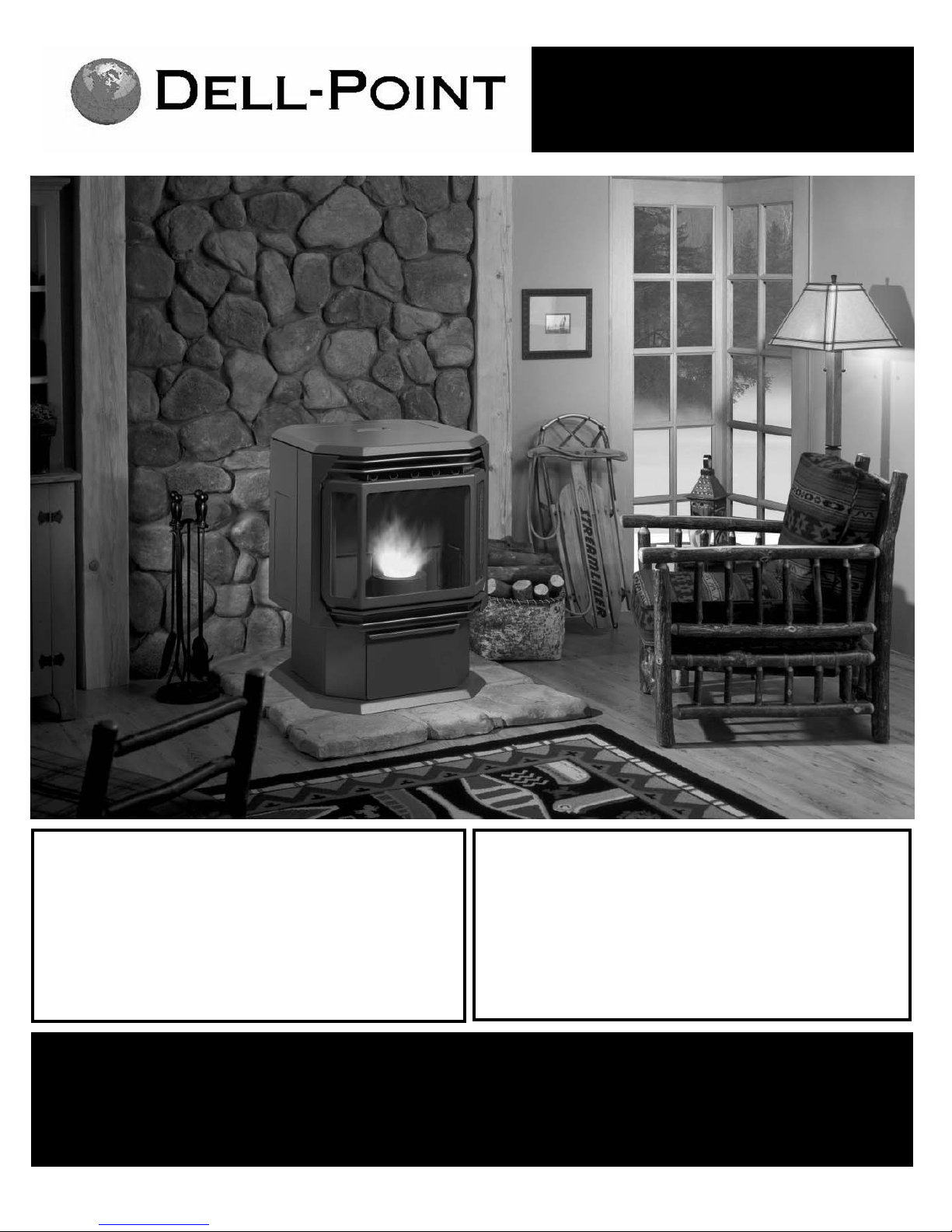
Greenfire GF45 BioEnergy Stove 5
INSTALLATION
IMPORTANT: SAVE THESE INSTRUCTIONS
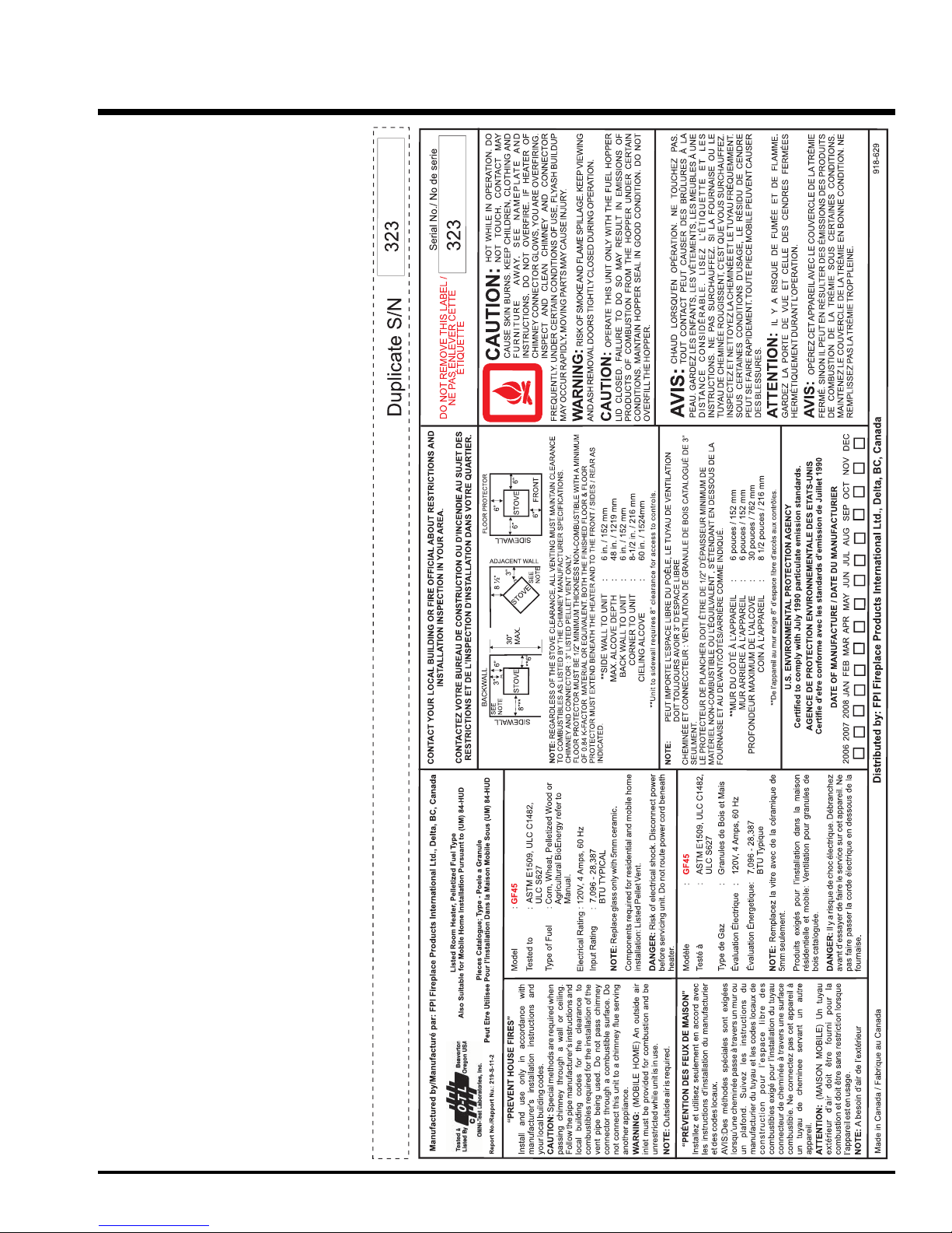
The GF45 Stove must be installed in accordance with these instructions.
Carefully read all the instructions in this manual first. Consult the building
authority having jurisdiction to determine the need for a permit prior to
starting the installation.
NOTE: Failure to follow the instructions could cause a malfunction of the
heater which could result in death, serious bodily injury, and/or property
damage. Failure to follow these instructions may also void your fire
insurance and/or warranty.
BEFORE YOU START
It is very important to ensure that the stove is installed in a safe manner.
Be aware of fire prevention rules and laws in your area. All applicable
National and Local codes must be met and complied with.
We recommend that your pellet stove be installed by an authorized
dealer / installer.
The stove’s electrical connection is to a standard grounded wall socket.
Special care should be taken so the connection cable is not damaged
in any way.
It is strongly recommended that you install a smoke detector as well as
an ABC type extinguisher near the stove. A power surge bar is also highly
recommended to protect the electrical components.
If the stove is installed by an uncertified installer, FPI will not be held
responsible for any faulty operation including poor performance of the
stove.
IMPORTANT SAFETY INFORMATION
Only use approved fuels in multi-fuel burning appliances. Failure to comply
with this may create a hazardous situation and will void all warranties.
Never attempt to re-start your stove until it has fully cooled down. Starting
your stove using a gel is only recommended during automatic ignition
failure.
Never use or store flammable products close to the stove while it’s in use,
or at any other time.
The Prime button is only used to prime the auger when Hopper is empty.
Do not use the manual feeding procedures to start-up your stove as
these will create smoke in your house.
Ensure that the ash pan door is securely closed at all times when the stove
is in use. Air pressure could ignite the gas accumulated in the burn-pot
creating an overdraft condition in the combustion chamber altering the
performance of the burn-pot.
The GF45 model will not feed fuel if the front door or hopper lid are not
fully closed and the firebox in a negative pressure situation. These are
safety functions of the appliance.
INSTALLATION
UNIT LOCATION
1. For optimum benefit from your appliance, speak to your professional
for help with your location.
2. The location you choose for your appliance can be a factor in how
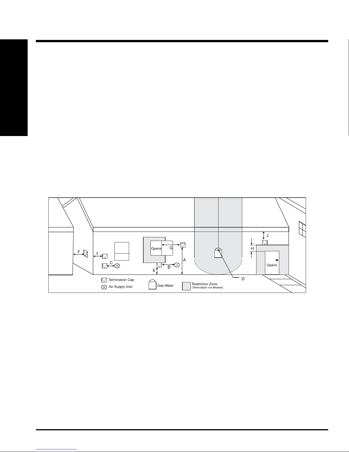
it will perform. Choose an interior location where the vent will not
be affected by any external interference, i.e. trees, bushes, walls or
fencing (refer to "Vent Termination Requirements" section). Make
sure, at the time of the installation, that there is the least possible
interference with the existing components of the house. Install a non
flammable covering when necessary. Place the stove according to
recommendations made on "Clearances" section or according to the
safety label fixed on the stove.
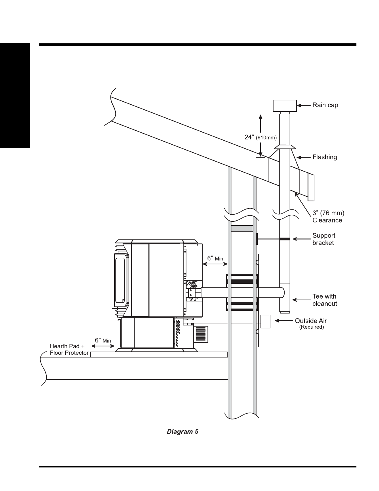
3. You can use the wall behind the stove to pass the chimney system
or simply join the stove to an existing chimney or a metal chimney,
with the use of an approved liner.
4. Ensure that all clearances to combustibles are met as per the safety
label and the diagrams on "Clearances" section.
5. This appliance requires outside air. Make sure that the outside
air supply does not come from a garage, an attic or any restricted
non-ventilated space. Air must come from the outside of the house
directly into the back of the stove.
6. This stove is not approved to be installed into a bedroom under any
circumstances.
7. The flooring under the stove must be made of a non-combustible
material, i.e. cement, ceramics, etc, and must extend at least 6"
(152mm) all around the stove. Refer to the diagrams on "Clearances"
section.
WHAT IS INCLUDED WITH THE GF45
Qty Description
1 pc User Manual
1 pc AC Power Inlet
1 pc Measuring Cup
1 pc Pipe Adapter Gasket
(for Pressure Reducer Plate)
1 pc Pressure Reducer Plate 1-1/4"
1 pc Pressure Reducer Plate 1-5/8"
1 pc Ash Poker
1 pc 7ft. 6in. Extension Cord
1 pc Outside Air Kit
IMPORTANT:
Stove must be cold before any attempt to clean the glass is made. Do
not use detergent containing abrasives to clean the windows or any
other parts of the stove. Use only recommended products found at
your local hearth shop for this type of cleaning.
IMPORTANT:
When cleaning the stove, always remove ashes into a steel container
and place outside the residence. Use gloves to handle or to empty
the ash pan.
IMPORTANT:
Before servicing the electrical panel, make sure that all electrical
sources is turned off to the stove and the power disconnected. Do
not forget to disconnect the battery, control board, fans and switches
as well.

Greenfire GF45 BioEnergy Stove6
INSTALLATION
CHIMNEY INSTALLATION
Important: Always use an approved 3” (76mm) PL type vent system
which is approved for venting while burning corn. Using a different
size vent will result in poor performance or eventual malfunction of
your appliance which is not covered under warranty. Never exceed 3"
diameter pipe.
Venting System
In order to get optimum performance from your appliance a good venting
system and positive air supply is essential.
Do not install a flue damper in the exhaust venting system of this unit.
Do not connect this unit to a chimney flue serving another appliance.
Type Of Chimney
Since this is a BioEnergy stove, it is necessary to use only venting rec-
ommended and approved for the burning of corn or other agricultural
fuels. Regular pellet vent cannot withstand the continued use of these
BioEnergy fuels and will deteriorate over time. Using recommended corn
vent will prolong the lifetime of your system.
Never use a non-approved pipe for the venting system. i.e. Dryer vent,
"B" vent for gas vent, PVC/plastic pipe or single wall chimney system.
It is very important to take note that for horizontal venting that the vent
length shall not exceed 48" (1219mm) chimney on an installation.
Always vent exhaust air to the outside atmosphere and never into enclosed
spaces, i.e. garage, car port etc. Vent systems can become hot to touch,
warn children of them to avoid the risk of burns.
Mobile Home Installation
The GF45 model is approved for installation in a mobile home of type
(UM) 84-HUD. The outside air connection must always go directly to the
atmosphere outside the building (refer to Diagram 2 in "Unit Dimensions"
section).
High Elevation
High altitude (6000' / 1828m and more) reduces the air velocity which
is drawn into the burn-pot. To help increase the air velocity, the chimney
must have a minimum of 6' (1.82m) of vertical vent outside the house
to help create a natural draught.
Negative Pressure In The House
The use of a bathroom fan, dryer, cooking hood fan, etc. can cause
negative pressure, especially in new air tight homes. Combined these
fans consume an average of 200 cfm, which is more powerful than the
combustion fan on the GF45, creating negative pressure around the stove.
To overcome this negative pressure, the GF45 requires the installation
of outside air from atmosphere directly to the 1" connector on the back
of the stove. (refer to Diagram 2 in "Unit Dimensions" section).
Pressure Reducer Plate
There are 2 Pressure Reducer Plates, one with a 1-1/4” and one with a
1-5/8" opening. These are sometimes needed in longer chimney runs or
in high altitude installations. The Pressure Reducer Plate is designed to
slow down the draft in your chimney in such situations.
1. Remove the 4 nuts & washers from the bolts from the combustion
exhaust outlet.
2. Install the desire pressure reducer plate to the combustion exhaust
outlet, ensuring that gaskets are replaced on both sides of the pressure
reducer plate. One gasket is placed on each side of the pressure
reducer plate.
3. Reverse step 1.
NOTE: Only 1 of the pressure reducer plates is used (not both). It
is recommended to try the reducer plate with the 1-5/8" opening
first.
INSTALLATION
FIRST FIRE
The FIRST FIRE in your stove is part of the paint curing process. To
ensure that the paint is properly cured, it is recommended that you burn
your fireplace for at least four (4) hours the first time you use it with the
fan on.
When first operated, the unit will release an odour caused by the curing
of the paint and the burning off of any oils remaining from manufacturing.
Smoke detectors in the house may go off at this time. Open a few
windows to ventilate the room for a couple of hours. The glass may
require cleaning.
NOTE: When the glass is cold and the appliance is lit, it may cause
condensation and fog the glass. This condensation is normal
and will disappear in a few minutes as the glass heats up.
DO NOT ATTEMPT TO CLEAN THE GLASS WHILE IT IS
STILL HOT!
OUTSIDE AIR KIT INSTALLATION
Remove the outside air kit package from the ash pan. The outside air kit
includes; 2 - 12" pipes, 2 - couplings and 1 - 90 degree elbow.
1) Secure the already attached coupling with pipe to the outside air
intake pipe.
2) Secure the other coupling with pipe to the pipe from step 1.
3) Secure the 90 degree elbow to the pipe from step 2. Ensure that the
elbow is pointed down and not up.
Back of stove shown

Greenfire GF45 BioEnergy Stove 7
INSTALLATION
INSTALLATION
UNIT DIMENSIONS
CLEARANCES
Alcove Ceiling height is 60" (324mm)
(measured from bottom of the unit.)
Floor Protector of 0.84k factor minimum
is required beneath the Hearth.
(Please check with local authorities and regulations.)

Greenfire GF45 BioEnergy Stove8
INSTALLATION
INSTALLATION
VENT TERMINATION REQUIREMENTS
1. Do not terminate the vent in any enclosed or semi-enclosed areas that can build up a concentration of fumes.
2. Vent surfaces can become extremely hot. Keep children away from such areas. Non-combustible shielding or guards may be required.
3. Termination must exhaust above the inlet elevation. It is recommended to have a short vertical run which will help in the event of total power
failure.
4. If the unit is incorrectly vented or the air to fuel mixture is out of balance, a slight discoloration of the exterior of the house might occur. Since
these factors are beyond the control of FPI we grant no guarantee against such incidents.
5. When installing into an existing masonry chimney, you will probably need a short horizontal section to clear the lintel and allow the hopper lid to
open. See diagram on page 13 for more details.
6. Do not terminate a vent underneath a veranda porch or deck unless fully open on a minimum of two sides beneath the floor.
NOTES:
- Vent terminations shall not be recessed into walls or siding.
- A vent shall not terminate directly above a sidewalk or paved driveway which is located between two single family dwellings
and serves both dwellings.
- If the vent termination is accessible, a certified guard shall be installed.
- Local codes or regulations such as CAN / CSA B365 or USA NFPA 211 may require different clearances. Check with your local
authorities.
IT IS RECOMMENDED THAT YOUR PELLET STOVE BE INSTALLED BY AN AUTHORIZED DEALER/INSTALLER.
The diagram below references all horizontal applications. For vertical applications refer to B365 for Canada and NFPA 211 for the US
along with pages 10 to 13 in this manual.
Min. Clearance Description
A 84" (2134mm) Above public walkway, sidewalk or street.
B 72" (1829mm) Within any gas regulator vent or mechanical air inlet to a building.
C 36" (914mm) Within a building opening, air inlet of another appliance, an oil tank vent or property boundry
D 36" (914mm) Horizontally of the vertical centerline of a gas meter/regulator and within height of 15ft. (4.5m) above.
E 12" (305mm) Above grade level or any non-combustible surface such as cement or gravel.
F 36" (305mm) To any building projection, adjacent wall or any combustible materials such as grass, trees, fencing, etc.
G 48" (1219mm) From beside/below any door or window that may be opened.
H 12" (305mm) Above any door or window that may be opened.
I 12" (305mm) To inside or outside corner.
J 24" (610mm) Below any eave or roof overhang.
Diagram 3

Greenfire GF45 BioEnergy Stove 9
INSTALLATION
INSTALLATION
HORIZONTAL TERMINATION
Top View
Side View

Greenfire GF45 BioEnergy Stove10
INSTALLATION
OUTSIDE VERTICAL TERMINATION
INSTALLATION
Side View

Greenfire GF45 BioEnergy Stove 11
INSTALLATION
INSTALLATION
VERTICAL TERMINATION
Top View
Side View
Diagram 6

Greenfire GF45 BioEnergy Stove12
INSTALLATION
EXISTING CLASS "A" CHIMNEY
INSTALLATION
Diagram 7

Greenfire GF45 BioEnergy Stove 13
INSTALLATION
INSTALLATION
EXISTING MASONRY CHIMNEY
Diagram 8

Greenfire GF45 BioEnergy Stove14
INSTALLATION
INSTALLATION
OPTIONAL 12 VOLT
BATTERY INSTALLATION
This battery back-up will ensure uninterupted operation of your stove
in the event of unexpected loss of electrical power. Note that this does
not replace the regular 120 volt power supply to the stove. The battery is
only a backup. The battery will generally last 6-9 hours on a full charge
(depending on feed rate). See "Electrical Diagram" section for details on
hook-up. It is recommended to have your battery connected at all times.
The battery will trickle charge whenever electrical power is restored and
will continue to charge througout the process.
If there is no battery connected, a power interruption in excess of 5
seconds, will cause the stove to immediately shutdown, once power is
restored the stove will need to be restarted. A power interruption of less
than 5 seconds will result in the stove picking up where it left off upon
restoration of power.
To facilitate the installation of a larger 12 volt battery we include, exten-
sion alligator clip leads in the battery installation kit.
Note: 12 volt batteries should never sit on stone or concrete.
HOW TO INSTALL THE BATTERY:
1) Remove battery cage and battery from kit.
2) Attach red positive wire to battery.
3) Attach black negative wire to battery.
4) Place battery into cage facing up.
5) Slide battery cage with battery inside over four screws and tighten.
6) Attach red battery wire to red wire from unit.
7) Attach black battery wire to black wire from unit.
Children should be kept away from the hot stove. For all other questions
contact your local dealer.
OPTIONAL GREENKEY
INSTALLATION
The Greenkey is needed in order to burn Corn or Wheat, without it you
can only burn wood pellets.
To install the Greenkey;
1) Open control panel cover.
2) Insert the GreenKey into keyhole.
3) Close control panel cover.
GreenKey
NOTE:
If the Greenkey is removed while burning corn or wheat you have 20
seconds to put the greenkey back in place before the unit automatically
goes into shut down mode.

Greenfire GF45 BioEnergy Stove 15
OPERATION
OPERATING INSTRUCTIONS
CONTROL PANEL FUNCTIONS
Prime Stove
This button is used only to prime the
auger when the Hopper is empty.
Select Fuel
This button is used to select the
appropriate fuel type that is going
to be burned.
Heat Level Settings
Select the desired heat level by
pressing -/+ buttons. Heat levels
range from 1 to 5 for all fuels.
Service
Allows you to change fan speed
settings and the ash feed auger
settings, using the "+" and "-" buttons
if necessary.
Stop Button
Stove goes into shut down mode
which takes 120 minutes.
Start Button
This button is used to ignite the
stove.

Greenfire GF45 BioEnergy Stove16
OPERATION
OPERATING INSTRUCTIONS
Priming Stove: Empty Hopper
1) Open the Hopper Lid and fill with desired fuel to be burned.
NOTE: The Hopper can hold up to a 45 pound bag of fuel.
2) Close Hopper Lid.
3) Open the front door and place the measuring cup in the center of the burn
pot directly under the feed tube. The measuring cup will need to be tilted
in order to fit under the feed tube.
4) Close the Front Door.
5) Open the Control Panel Cover and press the “Prime Stove” button once.
The Control Panel screen will display Prime Feed.
6) Wait 2 minutes to allow for the stove to prime. While the stove is priming
you will see fuel spilling into the measuring cup.
7) After 2 minutes the Control Panel will return to the main screen. Open
the front door and remove the measuring cup from the burn pot and pour
the fuel back into the hopper.
8) Close Hopper Lid and Front Door.
9) Proceed to the steps below to burning the desired fuel type.
NOTE: If the stove does not prime within 2 minutes, ensure that the Hopper
Lid and Front Door are properly closed. (The stove will not prime if the
front door or hopper lid are open.) Press the “Prime” button again.
Burning Wood Pellets: Primed Hopper
NOTE: If the hopper is empty, follow steps 1 to 8 to Prime Stove.
1) Open the control panel cover, and select the fuel type by pressing the
“Select Fuel” button until the screen displays Wood. The optional Green-
Key is only needed for additional fuels, without it the unit will burn wood
pellets only.
2) To ignite the stove press the “Start” button once and the screen will display
Ignition. Do not add any fuel to the burn pot. In Wood mode the stove
will fill the burn pot before starting ignition.
3) The ignition sequence will take approximately 7 minutes to complete.
After 3-4 minutes you should start to see smoke coming from the burn
pot. This is normal, it means that the igniter is working. When the pellets
ignite and flames appear the smoke will disappear.
IMPORTANT:
On start up, always use wood pellets when
operating unit from a cold start. Wood pellets
ensure a faster and hotter starting fire which
results in better performance.
STARTING
PROCEDURES
CAUTION: Do Not use the manual priming procedure for
starting of your stove as this may cause smoke in your resi-
dence. Like all solid fuel fires, the initial start-up is crucial to
the ongoing performance of your appliance. Failure to start
your fire properly can lead to frustrations and continued
re-light attempts.
To Start Your Stove
To facilitate your start up and regardless of fuel being utilized in your
stove, you must use wood pellets as fuel for starting. This will quickly
raise the burner and vent temperatures providing a better and faster start
up. Failure to use wood pellets will not ignite the stove. Before starting
each fire, first make sure the burn pot is completely emptied out.
Never attempt to start with a partly filled burn pot.
OPERATION GUIDELINES FOR
BURNING CORN & WHEAT
IMPORTANT: Compared to wood pellets, agricultural based
fuels such as Corn or Wheat require extra care, attention
and understanding. Failure to adhere to these operating
instructions could lead to Ash Auger failure, and /or build up
of ash in the Burn-pot leading to system failure. Such issues
are at the control of the operator and not to be considered
appliance problems. The physical characteristics and
composition of Corn and Wheat, are very different to that
of wood. Following these guidelines and directions will help
you better understand and control the performance of your
appliance while burning Corn or Wheat.
When burning Corn or Wheat, the following will help you understand and
establish control of the working parameters of the appliance for optimum
performance during operation.
Initial Use Of GF45 For
Burning Corn & Wheat
In order to become better acquainted with this new technology, we recom-
mend to the first time user of wood pellet fuel only for the first few days.
Once you are comfortable with the functions of the control pad and the
changes in operation when using the controls with wood pellets, you can
feel safe to move on to burning Corn or Wheat. Remember regardless
of the fuel you will be burning from your hopper, wood pellets must be
used to start your fire.
NOTE: To further ensure your start-up, after the initial 37 minutes, you
now have control of the keypad for adjustment purposes. However, the
keypad is protected to only allow single incremental rises and drops in
fuel feed for 25 minutes at a time. This means should you enter two level
changes to feed rate, i.e. from 3 to 5, the feed rate will first stabilize on
4 (3 lbs per hour) for a period of 25 minutes before increasing to 5 (4 lbs
per hour). This is to allow the fire to build up rather than create a potential
for extinguishing your fire.
As FPI does not have any control on quality or even the type of fuel mar-
keted, they assume no responsibility from any faulty operation related to
the type of fuel employed.
To Stop Stove
NOTE: The unit will take 120 minutes to shutdown completely.
1) Press the “Stop” button on the control panel.
2) The screen display will show Shut Down.

Greenfire GF45 BioEnergy Stove 17
OPERATION
OPERATING INSTRUCTIONS
Burning Corn or Wheat: Primed Hopper
NOTE: If the hopper is empty, follow steps 1 to 8 to Prime Stove.
1) Open the control panel cover, if the GreenKey has not yet been inserted
gently push the key into the keyhole on the control panel.
2) Select the fuel type by pressing the “Select Fuel” button until the appropri-
ate fuel type is displayed on the screen.
3) Press the “Start” button and the screen will display Manual Light.
4) Open the front door and pour 2-1/2 cups of wood pellets into the burn
pot. Ensure that the pellets are levelled out & cover the ignitor hole.
5) Close the front door.
6) Press the “Start” button again and the screen will display
Ignition.
7) The ignition sequence will take approximately 7 minutes to complete.
After 3-4 minutes you should start to see smoke coming from the burn
pot. This is normal, it means that the igniter is working. When the pellets
light and flames appear the smoke will disappear.
Selecting Proper Fuel Type
If you forget to select the proper fuel type. ie. set at wood but hopper is filled
with corn, the burn pot will fill with corn or wheat and will start smoking.
Immediately press the 'Stop' button and allow the unit to clean itself out.
The shutdown process will empty burn pot which takes 120 minutes.
NOTE: Do not open the door at any time.
Clinker Prevention
Clinkers are a result of incomplete combustion in your burn-pot and, if by
chance they occur, can be controlled with correct use of your controls.
Incomplete and poor combustion in your appliance is related to the level
of the fuel bed height, the level of combustion air, the temperatures in
your burn-pot, and the rate of ash extraction from your burn-pot.
In the event that clinkers start to form , you can use the “poker” provided
to gently break this formation and allow the unit to then continue as before.
If you must open the firebox door while the unit is in operation, (to break
a clinker), always open gently and slowly.
Diagram 9a: Calibration Indicator / Pressure Gauge
(located below control panel at the side of the unit)
High Fuel / Ember Bed Control
If under the above display conditions, you have accumulated a high
fuel/ember bed, the following guidelines should help you eliminate the
problem and stabilize the fuel bed for future use. These should be one-
time changes and settings for as long as you continue to use the same
fuel. i.e. Corn or Wheat.
Burn-pot fuel bed: If you cannot see 5” of the burn-pot wall above your
fuel/ember bed, the level is too high (refer to Diagram 9b in "Low Fuel/
Ember Bed Control" section).
1) Hold the 'Service' button down for approximately 6 seconds.
Low Fuel/ember Bed Control
If under above display conditions, you have accumulated a low fuel/ember
bed the following guidelines should help you eliminate the problem and
stabilize the fuel bed for future use.
Burn-pot fuel bed: If you see more than 5 ½” - 6” of the burn-pot wall
above your fuel/ember bed, the level is too low (refer to Diagram 9b).
After the initial start-up procedures and the unit has run undisturbed or
unaltered for at least one hour, visually check the combustion air flow and
ash removal indicator levels on the control panel by holding the 'Service'
button for approximately 6 seconds and check the settings for FAN and
ASH. They should read “10”.
If under these display conditions, you have a low fuel/ember bed, the fol-
lowing guidelines should help you eliminate the problem and stabilize the
fuel bed for future use. These should be one-time changes and settings for
as long as you continue to use the same fuel. i.e. Corn or Wheat.
1) Hold the 'Service' button down for approximately 6 seconds.
2) When FAN displays on the screen, gradually decrease the combustion
air to digital reading of “8” by pressing the "-" button. The default is
10, it ranges from 1 - 20.
3) Press the 'Service' button once and ASH will display, gradually de-
crease the ash removal to digital reading of “8” by pressing the "-"
button. The default is 10, it ranges from 1 - 20.
4) Press the 'Heat' button once to go back to main screen display.
This will reduce the rate of ash removal, allowing the fuel/ember bed to
build to the appropriate level. i.e. 5” from the top, or a 3” bed.
5"
Fuel/Ember Bed
Pellet
Feed
Tube
Ash Extraction
(Auger)
Diagram 9b
2) When FAN displays on the screen, gradually increase the combustion
air to digital reading of “12” by pressing the "+" button. The default
is 10, it ranges from 1 - 20.
3) Press the 'Service' button once and ASH will display, gradually in-
crease the ash removal to digital reading of “12” by pressing the "+"
button. The default is 10, it ranges from 1 - 20.
4) Press the 'Heat' button once to go back to main screen display.
At this point you will notice an increase in the pressure reading on the
round Pressure Gauge (refer to Diagram 9a) indicator located below the
control panel. This will fluctuate as you increase or decrease air flow. (This
is a good indicator to help you manage your settings.

Greenfire GF45 BioEnergy Stove18
MAINTENANCE
MAINTENANCE
MAINTENANCE
Maintenance Schedule Using Wood Pellets
Maintenance Schedule Using Corn or Wheat
COMPONENTS OF STOVE EACH START
UP
EVERY 2-3
DAYS
WEEKLY MONTHLY ANNUALLY
REMOVE ASH FROM WITHIN BURN-POT X
CHECK THE ASH REMOVAL SYSTEM X
EMPTY THE ASH PAN X
CLEAN THE COMBUSTION CHAMBER (STEP
1)
X
CLEAN THE BURN-POT JETS X
CLEAN THE CONVECTION PIPES SYSTEM X
CLEAN THE CONVECTION FAN (FLYWHEEL)X
CHECK THE BATTERY CONDITIONS X
CLEAN THE COMBUSTION CHAMBER (STEP
2)
X
CLEAN THE COMBUSTION FAN (FLYWHEEL)X
INSPECT THE SEALS X
CLEAN THE CHIMNEY X
INSPECT IGNITOR & TUBES X
COMPONENTS OF STOVE EACH START UP WEEKLY MONTHLY ANNUALLY
REMOVE ASHES IN BURN-POT X
CHECK THE ASH REMOVAL SYSTEM X
EMPTY THE ASH PAN X
VACUUM OUT THE COMBUSTION CHAMBER
(STEP 1)
X
CLEAN THE BURN-POT JETS X
CLEAN THE CONVECTION PIPES SYSTEM X
CHECK THE BATTERY CONDITIONS X
CLEAN THE CONVECTION FAN (FLYWHEEL)X
CLEAN THE COMBUSTION CHAMBER
(STEP 2)
X
CLEAN THE COMBUSTION FAN (FLY-
WHEEL)
X
INSPECT THE SEALS X
CLEAN THE CHIMNEY X
INSPECT IGNITOR & TUBES X
IMPORTANT NOTE:
Always disconnect the power to your stove before doing any maintenace or
repairs. Only a qualified technician should take care of any electrical problems.

Greenfire GF45 BioEnergy Stove 19
MAINTENANCE
Before each start-up, always check the level of ashes
in the ash pan and remove if necessary. “Be sure to
dispose of in a metal container and remove to outside of
the building.” Embers can stay hot for a long time after
the fire has been extinguished.
Tools Required
Ratchet;
12” extension;
5/16” socket, wrench and nut driver;
7/16” socket, wrench and nut driver;
9/16” wrench;
1/8”, 5/32", 3/16" Allen wrench;
¼” nut driver;
Straight blade and Phillips head No. 2 screwdrivers;
Small Rubber mallet;
3/8” drill;
3” round wire brush that can be connected to a drill;
1/8” mini steel brush;
Small brass wire brush;
Vacuum cleaner with filter;
High temperature lubricant for ash cleaning gears;
Maintenance Of The
Combustion Chamber
STEP 1: Once a month, use a "shop-vac" style vacuum cleaner (avoid
the use of a domestic style vacuum cleaner) with filter (only when the
stove is cold) to remove the ashes accumulated around the burn-pot
(Diagram 10). Clean the interior of the glass door. Use the "shop-vac"
style vacuum cleaner brush to clean the pipes of the convection system
(Diagram 11) as well as the exhaust outlet (Diagram 12).
Diagram 10
BURN-POT
Diagram 11
CONVECTION
SYSTEM
Diagram 12
EXHAUST OUTLET
Diagram 13
ACCESS
DOOR
Diagram 14
MAINTENANCE
STEP 2: The frequency of cleaning varies according to the type of fuel
burned (see maintenance charts) For an in-depth cleaning, repeat STEP
1. It maybe necessary to use a rubber mallet to remove the four cleaning
doors inside the firebox. Hold the vacuum cleaner under the side wall
and use a rubber mallet to lightly knock out accumulated ashes which
are inaccessible with the vacuum cleaner (refer to Diagram 14).
Before re-installing the access doors refer to the section on the
maintenance of the combustion fan, clean the wings on the flywheel.

Greenfire GF45 BioEnergy Stove20
MAINTENANCE
Diagram 17
Diagram 18
TOP
RING
Maintenance Of The Burn-pot
Step 1: Use a 9/16 wrench to unscrew the two nuts (Diagram 17). Then
to raise the ring, it may be necessary to insert a flat screwdriver between
the outside of the burn-pot and the top ring (Diagram 18). If required,
use a rubber mallet to loosen.
Diagram 19
CYLINDER
BURN-POT
Step 4: Use a rod which has a diameter of 1/8" (3 mm) to clean the
jets of the inner burn-pot (Diagram 20). Be sure to install the burn-pot
cylinder the correct way up. Angled holes to the top, straight holes to
the bottom.
Diagram 20
INNER
BURN-POT
Step 2: Remove the cylinder from inside the burn-pot (Diagram 19).
Maintenance Of The
Ash-extraction System
Step 1: Refer to Diagram 15 to determine the condition of the three
stainless steel ash screws. Sugars released by corn or wheat can stick
to the ash screws resulting in poor movement and ash removal. Check
by removing the ash-extraction system or look inside the burn pot.
Diagram 16
Diagram 15
Step 2: Use a 9/16 wrench to unscrew the two nuts (Diagram 17). Then
to raise the ring, it may be necessary to insert a flat screwdriver between
the outside of the burn-pot and the top ring (Diagram 18). If required, use
a rubber mallet to loosen.
Step 3: Refer to Diagram 16. It is advisable to support the ash extraction
system before you undo these 9/16" nuts as once they are removed, the
ash extraction system will become loose and drop down. The "lovejoy"
connection will now be loose. This is an important part that must not be
misplaced or forgotten when re-assembling. Once removed soak screws
in warm water to remove deposits stuck to them from burning corn or
wheat, and use a copper based lithium grease on the auger gears.
Step 3: If necessary, use a steel brush installed onto a drill to remove
minerals stuck to the interior wall of the cylinder.
MAINTENANCE
This manual suits for next models
1
Table of contents
Other FPI Stove manuals
Popular Stove manuals by other brands

Soto
Soto AMICUS instruction manual

Eco-ideal
Eco-ideal eco 1 Installation and operating instructions

MBS
MBS THERMO VULKAN Manual instruction

THERMOROSSI
THERMOROSSI WAIR6 Installation, use and maintenance guide

Wonderfire
Wonderfire 530U PRESIDENT Installer's guide

Coleman
Coleman FYRESTORM 9770 Instructions for use

Regency
Regency ULTIMATE U41FS-LP Installation and operating instructions

Masterbuilt
Masterbuilt MPC 230B user manual

Coleman
Coleman Apollo 9760-A25 Instructions for use

Dometic
Dometic ORIGO 2000 operating manual

IRON
IRON IRHP-12-2B Installation & operation manual

GAS ONE
GAS ONE B-5400 Owner's Manual and Operating Instructions